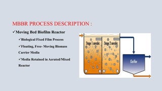
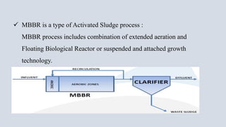
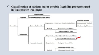
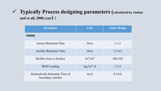
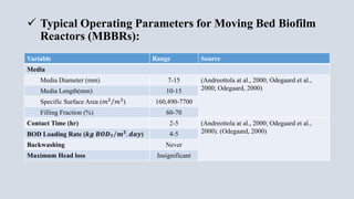
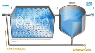
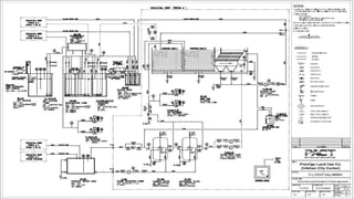
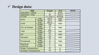
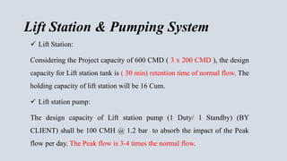
The document provides an overview of moving bed biofilm reactors (MBBR) for wastewater treatment. It discusses the history and introduction of MBBR technology, key designing parameters such as media size and surface area, and operating parameters like retention times and loading rates. An example design for a 600 cubic meter per day MBBR wastewater treatment plant is presented, outlining the treatment process flow including aeration, settling, and disinfection. Finally, the document reviews a paper comparing the treatment performance of MBBR versus conventional activated sludge systems.


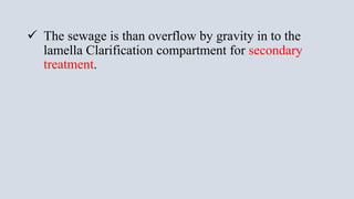
![3.0 AERATION SYSTEM
3.1 & 3.2 Aeration Tank & Floating Media
ITEM DESCRIPTION REMARKS
Qty. One (1)
No. Chambers/ Tank Two (2)
Tank Make PACT
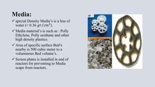
Media
Type 2P-836 P H O T O
Material HDPE
Surface 836 [m²/m³]
Protected Surface 494 [m²/m³]
Weight 165 [kg/m³]
Volume/Tank 15.0 m3
TANK
Material
BODY Carbon Steel, 4.75 mm,
Paint Epoxy Paint, internal: 300 Micron, External: 150 micron.
TANK
Dimension
Tank/Each 10 m Container (L10.0 x W 2.4 x H (2.65+0.2))
Aeration
Chamber
L 6.5 x W 2.4 x H (2.60 + 0.25 )
Volume
Effective 40.5 M3
Total 44.4 M3
Pipe
Size
IN
Water DN 50
Actual
sizes will
be at final
design
Air Main DN 80
OUT (Water) Opening With Screen
Drain DN 50
Over Flow DN 50 (2”)
Connection Type Flange, PN 10
Accessories
/
Tank
Two (2) Drain Pit with drain valve, 2”
Inlet & Outlet Screen
One (1) Ladder](https://image.slidesharecdn.com/mbbr-150515131444-lva1-app6891/85/Mbbr-29-320.jpg)
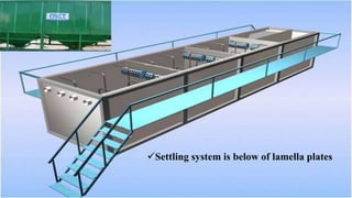
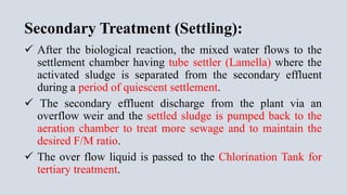
![4.0 SETTLING SYSTEM
4.1 SETTLING TANK
ITEM DESCRIPTION REMARKS
Qty. One (1)
Included in
item 3.1
Actual
sizes will
be at final
design
No. Chambers/ Tank One (1)
Tank Make PACT
TANK
Material
BODY Carbon Steel, 4.75 mm,
Paint Epoxy Paint, internal: 300 Micron, External: 150 micron.
TANK
Dimension
Tank/Each (L 3.5 x W 2.4 x H (2.5+0.3))
Chamber L 3.5 x W 2.4 x H (2.5 + 0.3 )
Sludge
Collection
System
Hopper
Bottom
No. One (1)
Angle (55-60) O
Valve
Type Ball / Manual
Size DN 80 (3”)
Qty. One (1)
Material
Body PVC
Disk NA
Pipe
Size
Inlet Opening with Screen
Outlet DN 80(3”)
Over Flow NA
Connection Type Flange, PN 10
Weir
Material C.S Plate, 4.0 mm Sheet,
No. of Weirs/Tank One (1)
Length Weir Plate 2.3 M/Tank
# V notches As final Design
Accessories
/ Tank
One (1) Drain Pit.
One (1) Ladder
4.1.1 Lamella Tube Settler.
Type PE Sheets P H O T O
Actual sizes will
be at final
design
Make xxx
Material PE
Volume / Tank 8.40 m³ Total Volume 8.40 m³
Sedimentation Area
55O 6.25 [m²/m³]
60O 7.0 [m²/m³]
Protected Surface 494 [m²/m³]
Weight 35.0kg/ m³
Volume/Tank Final Design](https://image.slidesharecdn.com/mbbr-150515131444-lva1-app6891/85/Mbbr-30-320.jpg)