The document discusses various types of secondary wastewater treatment processes. It describes suspended growth processes like the activated sludge process, which uses a mixed liquor of wastewater and microorganisms in an aeration tank. The microorganisms consume organic matter producing more cells and byproducts. Secondary clarification separates the cells for return to the aeration tank. Attached growth processes like aerated lagoons also use microorganisms to consume organic matter through surface aeration.
Deals with primary sedimentation tanks for the primary treatment of sewage. settling column test, settling profile graph construction and use of the settling profile graph for the design of primary sedimentation tank. both circular and rectangular settling tanks are described here.
Lecture notes of Environmental Engineering-II as per Solapur university syllabus of TE CIVIL.
Prepared by
Prof S S Jahagirdar,
Associate Professor,
N K Orchid college of Engg and Technology,
Solapur
Deals with UASB reactors for the primary treatment of sewage, stabilization of sludge and removal of BOD. Various components of a UASB reactor are described and design details are included. Modifications to UASB such as UASB ponds, Anaerobic baffle reactors, migrating blanket reactors are also described here.
Lecture notes of Environmental Engineering-II as per Solapur university syllabus of TE CIVIL.
Prepared by
Prof S S Jahagirdar,
Associate Professor,
N K Orchid college of Engg and Technology,
Solapur
Lecture note of Industrial Waste Treatment (Elective -III) as per syllabus of Solapur university for BE Civil
Prepared by
Prof S S Jahagirdar,
Associate Professor,
N K ORchid College of Engg and Tech,
Solapur
Lecture notes of Environmental Engineering-II as per Solapur university syllabus of TE CIVIL.
Prepared by
Prof S S Jahagirdar,
Associate Professor,
N K Orchid college of Engg and Technology,
Solapur
Trickling Filter
A trickling filter is a type of wastewater treatment system.
• A trickling filter , also called trickling biofilter, biofilter, biological filter and biological trickling filter , is a fixed-bed, biological
reactor that operates under (mostly) aerobic conditions.
Aerated lagoon shortly known as lagoon is widely used to the purpose of waste water treatment. It is a biological treatment process. No extra chemical is required for this process.
Deals with what is activated sludge, mechanisms and kinetics of treatment, design of activated sludge process, secondary clarifiers and their design and bulking sludge, raising sludge and foaming of ASP.
Lecture note of Industrial Waste Treatment (Elective -III) as per syllabus of Solapur university for BE Civil
Prepared by
Prof S S Jahagirdar,
Associate Professor,
N K ORchid College of Engg and Tech,
Solapur
Lecture notes of Environmental Engineering-II as per Solapur university syllabus of TE CIVIL.
Prepared by
Prof S S Jahagirdar,
Associate Professor,
N K Orchid college of Engg and Technology,
Solapur
Trickling Filter
A trickling filter is a type of wastewater treatment system.
• A trickling filter , also called trickling biofilter, biofilter, biological filter and biological trickling filter , is a fixed-bed, biological
reactor that operates under (mostly) aerobic conditions.
Aerated lagoon shortly known as lagoon is widely used to the purpose of waste water treatment. It is a biological treatment process. No extra chemical is required for this process.
Deals with what is activated sludge, mechanisms and kinetics of treatment, design of activated sludge process, secondary clarifiers and their design and bulking sludge, raising sludge and foaming of ASP.
Lecture note of Industrial Waste Treatment (Elective -III) as per syllabus of Solapur university for BE Civil
Prepared by
Prof S S Jahagirdar,
Associate Professor,
N K ORchid College of Engg and Tech,
Solapur
This content is benificial for the research and development purposes. Students and research scholars who they are eager to search for the conventional waste water treatment methods are look here.
Use of biotechnology in the treatment of municipal wastes and hazardousindust...Sijo A
Industrial waste water is a type of waste water produced by industrial activity, such as that of factories, mills and mines.
It is characterised by its large volume, high temperature, high concentration of biodegradable organic matter and suspended solids, high alkanity or acidity and by variations of flow.
The treatment of wastes by micro-organisms is called biological waste treatment.
A report for my Environmental Management for Food Industries
This focused on the first stage in wastewater treatment
Foe the video slide:
https://www.youtube.com/watch?v=GV-DoisLwm0
TECHNICAL TRAINING MANUAL GENERAL FAMILIARIZATION COURSEDuvanRamosGarzon1
AIRCRAFT GENERAL
The Single Aisle is the most advanced family aircraft in service today, with fly-by-wire flight controls.
The A318, A319, A320 and A321 are twin-engine subsonic medium range aircraft.
The family offers a choice of engines
Explore the innovative world of trenchless pipe repair with our comprehensive guide, "The Benefits and Techniques of Trenchless Pipe Repair." This document delves into the modern methods of repairing underground pipes without the need for extensive excavation, highlighting the numerous advantages and the latest techniques used in the industry.
Learn about the cost savings, reduced environmental impact, and minimal disruption associated with trenchless technology. Discover detailed explanations of popular techniques such as pipe bursting, cured-in-place pipe (CIPP) lining, and directional drilling. Understand how these methods can be applied to various types of infrastructure, from residential plumbing to large-scale municipal systems.
Ideal for homeowners, contractors, engineers, and anyone interested in modern plumbing solutions, this guide provides valuable insights into why trenchless pipe repair is becoming the preferred choice for pipe rehabilitation. Stay informed about the latest advancements and best practices in the field.
Final project report on grocery store management system..pdfKamal Acharya
In today’s fast-changing business environment, it’s extremely important to be able to respond to client needs in the most effective and timely manner. If your customers wish to see your business online and have instant access to your products or services.
Online Grocery Store is an e-commerce website, which retails various grocery products. This project allows viewing various products available enables registered users to purchase desired products instantly using Paytm, UPI payment processor (Instant Pay) and also can place order by using Cash on Delivery (Pay Later) option. This project provides an easy access to Administrators and Managers to view orders placed using Pay Later and Instant Pay options.
In order to develop an e-commerce website, a number of Technologies must be studied and understood. These include multi-tiered architecture, server and client-side scripting techniques, implementation technologies, programming language (such as PHP, HTML, CSS, JavaScript) and MySQL relational databases. This is a project with the objective to develop a basic website where a consumer is provided with a shopping cart website and also to know about the technologies used to develop such a website.
This document will discuss each of the underlying technologies to create and implement an e- commerce website.
Overview of the fundamental roles in Hydropower generation and the components involved in wider Electrical Engineering.
This paper presents the design and construction of hydroelectric dams from the hydrologist’s survey of the valley before construction, all aspects and involved disciplines, fluid dynamics, structural engineering, generation and mains frequency regulation to the very transmission of power through the network in the United Kingdom.
Author: Robbie Edward Sayers
Collaborators and co editors: Charlie Sims and Connor Healey.
(C) 2024 Robbie E. Sayers
CFD Simulation of By-pass Flow in a HRSG module by R&R Consult.pptxR&R Consult
CFD analysis is incredibly effective at solving mysteries and improving the performance of complex systems!
Here's a great example: At a large natural gas-fired power plant, where they use waste heat to generate steam and energy, they were puzzled that their boiler wasn't producing as much steam as expected.
R&R and Tetra Engineering Group Inc. were asked to solve the issue with reduced steam production.
An inspection had shown that a significant amount of hot flue gas was bypassing the boiler tubes, where the heat was supposed to be transferred.
R&R Consult conducted a CFD analysis, which revealed that 6.3% of the flue gas was bypassing the boiler tubes without transferring heat. The analysis also showed that the flue gas was instead being directed along the sides of the boiler and between the modules that were supposed to capture the heat. This was the cause of the reduced performance.
Based on our results, Tetra Engineering installed covering plates to reduce the bypass flow. This improved the boiler's performance and increased electricity production.
It is always satisfying when we can help solve complex challenges like this. Do your systems also need a check-up or optimization? Give us a call!
Work done in cooperation with James Malloy and David Moelling from Tetra Engineering.
More examples of our work https://www.r-r-consult.dk/en/cases-en/
Vaccine management system project report documentation..pdfKamal Acharya
The Division of Vaccine and Immunization is facing increasing difficulty monitoring vaccines and other commodities distribution once they have been distributed from the national stores. With the introduction of new vaccines, more challenges have been anticipated with this additions posing serious threat to the already over strained vaccine supply chain system in Kenya.
Immunizing Image Classifiers Against Localized Adversary Attacksgerogepatton
This paper addresses the vulnerability of deep learning models, particularly convolutional neural networks
(CNN)s, to adversarial attacks and presents a proactive training technique designed to counter them. We
introduce a novel volumization algorithm, which transforms 2D images into 3D volumetric representations.
When combined with 3D convolution and deep curriculum learning optimization (CLO), itsignificantly improves
the immunity of models against localized universal attacks by up to 40%. We evaluate our proposed approach
using contemporary CNN architectures and the modified Canadian Institute for Advanced Research (CIFAR-10
and CIFAR-100) and ImageNet Large Scale Visual Recognition Challenge (ILSVRC12) datasets, showcasing
accuracy improvements over previous techniques. The results indicate that the combination of the volumetric
input and curriculum learning holds significant promise for mitigating adversarial attacks without necessitating
adversary training.
Industrial Training at Shahjalal Fertilizer Company Limited (SFCL)MdTanvirMahtab2
This presentation is about the working procedure of Shahjalal Fertilizer Company Limited (SFCL). A Govt. owned Company of Bangladesh Chemical Industries Corporation under Ministry of Industries.
About
Indigenized remote control interface card suitable for MAFI system CCR equipment. Compatible for IDM8000 CCR. Backplane mounted serial and TCP/Ethernet communication module for CCR remote access. IDM 8000 CCR remote control on serial and TCP protocol.
• Remote control: Parallel or serial interface.
• Compatible with MAFI CCR system.
• Compatible with IDM8000 CCR.
• Compatible with Backplane mount serial communication.
• Compatible with commercial and Defence aviation CCR system.
• Remote control system for accessing CCR and allied system over serial or TCP.
• Indigenized local Support/presence in India.
• Easy in configuration using DIP switches.
Technical Specifications
Indigenized remote control interface card suitable for MAFI system CCR equipment. Compatible for IDM8000 CCR. Backplane mounted serial and TCP/Ethernet communication module for CCR remote access. IDM 8000 CCR remote control on serial and TCP protocol.
Key Features
Indigenized remote control interface card suitable for MAFI system CCR equipment. Compatible for IDM8000 CCR. Backplane mounted serial and TCP/Ethernet communication module for CCR remote access. IDM 8000 CCR remote control on serial and TCP protocol.
• Remote control: Parallel or serial interface
• Compatible with MAFI CCR system
• Copatiable with IDM8000 CCR
• Compatible with Backplane mount serial communication.
• Compatible with commercial and Defence aviation CCR system.
• Remote control system for accessing CCR and allied system over serial or TCP.
• Indigenized local Support/presence in India.
Application
• Remote control: Parallel or serial interface.
• Compatible with MAFI CCR system.
• Compatible with IDM8000 CCR.
• Compatible with Backplane mount serial communication.
• Compatible with commercial and Defence aviation CCR system.
• Remote control system for accessing CCR and allied system over serial or TCP.
• Indigenized local Support/presence in India.
• Easy in configuration using DIP switches.
Event Management System Vb Net Project Report.pdfKamal Acharya
In present era, the scopes of information technology growing with a very fast .We do not see any are untouched from this industry. The scope of information technology has become wider includes: Business and industry. Household Business, Communication, Education, Entertainment, Science, Medicine, Engineering, Distance Learning, Weather Forecasting. Carrier Searching and so on.
My project named “Event Management System” is software that store and maintained all events coordinated in college. It also helpful to print related reports. My project will help to record the events coordinated by faculties with their Name, Event subject, date & details in an efficient & effective ways.
In my system we have to make a system by which a user can record all events coordinated by a particular faculty. In our proposed system some more featured are added which differs it from the existing system such as security.
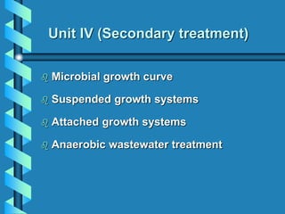
1. Unit IV (Secondary treatment)
Microbial growth curve
Suspended growth systems
Attached growth systems
Anaerobic wastewater treatment
2. Clarifier
Overview of wastewater treatment scheme
Secondary Sludge
Primary Sludge
Clarifier
Raw Wastewater Influent
PRIMARY
DISINFECTION
Biological
Treatment
System
SECONDARY
Clean Wastewater Effluent
Discharge to Receiving Waters
Preliminary Residuals
(i.e., grit, rags, etc.)
A
B
C
Wastewater
Treatment
Residuals
Biosolids
Processing
and Disposal
(e.g., attached-grwoth
Suspended-Growth,
Constructed Wetland, etc.)
Clarifier
PRELIMINARY
Usually to Landfill
3. Wastewater treatment processes
Preliminary treatment is a physical process that
removes large contaminants (screening).
Primary treatment involves physical sedimentation of
particulates.
Secondary treatment involves biological treatment to
reduce organic load of wastewater.
Tertiary or advanced treatments.
7. Inoculation Techniques
Two Forms of Medium
• Broth - a liquid medium
• Agar - a semi-solid medium
– agar is chemical from seaweed that melts at
100C and freezes at 45C
Agar medium is used for the isolation of
microbes- Streak Plates
9. Cell Division
Most Bacteria Reproduce by Binary
Fission
• The cell doubles in size
• Replicates the chromosome (DNA)
• Forms a septum in the center
• Synthesizes a Cell Wall at the Septum
• Daughter cells separate.
11. Bacterial Growth Curve
All microorganisms undergo similar growth
patterns.
Each growth curve has 4 phases.
Lag Phase
– occurs immediately after inoculation.
– cells do not grow; cells per volume do not
increase.
– If at all there is a slight increase in cell mass
and volume, but no increase in cell number.
14. Growth Phase
• Exponential/logarithmic Phase
• During this phase, the cells get adjusted to
their new environment and multiply rapidly,
growing at the maximum rate possible.
• Cells per volume increases dramatically
Bacterial Growth Curve
18. Death Phase
• Death Rate exceeds Growth Rate
• Cells per volume decreases
• Due to:
– Very low concentrations of Nutrients
– Very high concentrations of Waste Products
Bacterial Growth Curve
19. Important Terms
Growth Rate
• Number of doublings (cell divisions) per
hour
Doubling Time
• Length of time required for a cell to divide
during logarithmic growth
• Doubling Time = 1/Growth Rate
20. Growth Rate Examples
If cells double in 15 min.
• 15 min = 0.25 hr
• 1/0.25 = 4
If cells double in 300 min
• 300 min = 5 hr
• 1/5 = 0.2
Growth Rate = doublings per hour
21. Secondary treatment
• Secondary wastewater treatment is the second stage of
wastewater treatment that takes place after primary
treatment process.
• The process removes or reduces contaminants that are left
in the wastewater from the primary treatment process.
• Usually biological treatment is used to treat wastewater in
this step because it is the most effective type of treatment
on bacteria.
• Usually, secondary treatment involves the removal of
biodegradable dissolved and colloidal organic matter using
aerobic biological treatment processes.
22. • Aerobic biological treatment is performed in the presence
of O2 by aerobic microorganisms (principally bacteria) that
metabolize the organic matter in the wastewater, thereby
producing more microorganisms and inorganic end-
products (principally CO2, NH3, and H2O).
• Remove up to 90% of the organic matter in wastewater.
• The two most common conventional methods used to
achieve secondary treatment are attached growth
processes and suspended growth processes.
23. High-rate biological processes
• Characterized by relatively small reactor volumes and high
concentrations of microorganisms compared with low rate
processes.
• The growth rate of new organisms is much greater in high-
rate systems because of the well controlled environment.
• The microorganisms must be separated from the treated
wastewater by sedimentation to produce clarified secondary
effluent.
• The sedimentation tanks used in secondary treatment is
referred to as secondary clarifiers.
• The secondary sludge is normally combined with primary
sludge for sludge processing.
25. Activated-Sludge Process
• Activated sludge process is a process for treating sewage
and industrial wastewater using air and a biological floc
composed of bacteria and protozoa.
26. Activated-Sludge Process
• This system has two parts, an aeration tank and a settling
tank.
• The aeration tank has "sludge", which is nothing but a
mixed microbial culture (contains mostly bacteria, as well
as protozoa, fungi, algae, etc).
• This sludge is constantly mixed and aerated either by
compressed air bubblers located along the bottom, or by
mechanical aerators on the surface.
• The wastewater to be treated enters the tank and mixes
with the culture, which uses the organic compounds for
growth producing more microorganisms and results mostly
in the formation of carbon dioxide and water.
27. Activated-Sludge Process
• After the sludge has the proper amount of aeration time, it
is carried into the settling tank.
• The sludge collected at the bottom is then recycled to the
aeration tank to consume more organic material.
• Activated sludge - By the time the sludge is returned to
the aeration tank, the microorganisms have been in an
environment depleted of food for some time, and are in a
hungry (or activated) condition, eager to start
biodegrading some more wastes.
• Since the amount of microorganisms (or biomass),
increases as a result of this process, some biomass is
removed on a regular basis for further treatment and
disposal, adding to the solids produced in primary
treatment.
28. Activated-Sludge Process
• General types of ASP: plug flow, complete mix and SBR.
• Operated under aerobic/anaerobic.
• Hydraulic retention time in the aeration tanks usually
ranges from 3 to 8 hours but can be higher with high
BOD5 wastewaters.
29. Activated-Sludge Process
Description of Basic Process
• Three basic components:
1. A reactor in which the microbes responsible for
treatment are kept in suspension and aerated.
2. Liquid solid separation – usually sedimentation tank
3. A recycle system for returning a part of the solid
removed from the liquid-solid separation unit back to
the reactor.
33. Introduction: Definitions of Terms
ACTIVATED SLUDGE
floc of microorganisms that form when wastewater is aerated
MIXED LIQUOR
mixture of activated sludge and wastewater in the aeration
tank
MIXED LIQUOR SUSPENDED SOLID (MLSS)
measure of the amount of suspended solids in the mixed
liquor, mg/l
MIXED LIQUOR VOLATILE SUSPENDED SOLID
(MLVSS)
proportional to the microorganisms concentration in the
aeration tank
34. Introduction: Terminology
MEAN CELL RESIDENCE TIME (MCRT)
the average time a microorganism spends in the treatment
process
FOOD TO MICROORGANISM RATIO (F/M)
ratio of the amount of food expressed as mg of COD (or BOD)
applied per day, to the amount of microorganisms.
RETURN ACTIVATED SLUDGE (RAS)
settled mixed liquor collected in the clarifier underflow and
returned to the aeration basin
35. Introduction: Terminology
WASTE ACTIVATED SLUDGE (WAS)
excess growth of microorganisms which must be removed to
keep the biological system in balance. Various control
techniques have been developed to estimate the amount of WAS
that must be removed from the process
COMPLETE MIX ACTIVATED SLUDGE
an ideal mixing situation where the contents of the aeration tank
are at a uniform concentration
PLUG FLOW ACTIVATED SLUDGE
an ideal situation where the contents of the aeration tank flows
along the length of the tank
38. Air supply and process modifications:
Conventional system
Tapered aeration
Step aeration
Complete mix system
Contact stabilization
High rate
Extended aeration
39. Conventional system
Aeration and mixing is achieved at a fairly uniform rate
over the length of aeration tank.
Extremely low oxygen concentration prevail at the inlet
end of the tank.
At the outlet end, the oxygen supply can be more than
that required for the process.
42. Step aeration Influent addition at intermediate points
provides more uniform organic
removal throughout tank
43. Contact stabilization
Biomass adsorbs organics in contact basin and settles out in
secondary clarifier; the thickened sludge is aerated before being
return to the contact basin
44. High rate
Short detention time and high F/M ratio in aerator to maintain
culture in log-growth phase
46. Activated Sludge Process Design
1. The aeration basin volume
2. The amount of sludge production
3. The amount of oxygen needed
4. The effluent concentration of important parameters
47. The amount of sludge production
Where;
PX = sludge production rate
XT = Mixed Liquor Suspended Solid (MLSS) concentration
V = reactor volume
SRT = Solid Retention Time
SRT
V
X
P T
X
48. SOLUTION
Example
An activated sludge plant is operated at SRT value of 10
day. The reactor volume is 10 000m3 and MLSS
concentration is 400 g/m3. Determine the sludge production
rate.
day
kg
day
g
P
day
m
m
g
P
SRT
V
X
P
x
x
T
X
/
400
/
10
400
10
)
10000
(
/
400
3
3
3
49. Aeration System
Aeration system design must be adequate to:
1. Satisfy BOD of the waste
2. Satisfy the oxygen demand for nitrification
3. Provide adequate mixing
4. Maintain minimum dissolved oxygen conc. throughout the
aeration tank
50. Aeration System
• Two basic methods of aerating w/w:
1. To introduce air or pure oxygen into the w/w with
submerged diffusers or other aeration devices.
2. To agitate the w/w mechanically so as to promote
solution of air from the atmosphere.
Types of aeration system:
1. Diffused-air systems
2. Mechanical aeration
3. High purity oxygen system
51. Secondary Clarification
Secondary clarifiers for activated sludge must accomplish two
objectives:
1. Produce an effluent sufficiently clarified to meet discharge
standards
2. Concentrate the biological solids to minimize the quantity
of sludge that must be handled.
52. Aerated Lagoons
• Oxygen is usually supplied by means of surface aerators.
As with other suspended-growth systems, the turbulence
is created by the aeration devices.
• A large liquid detention time: Since they do not have
sludge recycle, the SRT is approximately equal to the
liquid detention time. Therefore, typical SRTs of 5 days for
heterotrophic BOD removal or 25 days for nitrification
require liquid detention times in the order of 5 and 25
days.
53. • A shallow depth: The typical depths of aerated lagoons
range from 1 to 3 m.
• Surface aeration: Although diffused aeration is sometimes
used, most aerated lagoons used high-speed surface
aerator as high surface area is available, the costs of high-
speed surface aerators is low, and there is flexibility in
locating high-speed surface aerators to maintain good solids
mixing.
54. Advantages
• Lagoon systems can be cost-effective to design and
construct in areas where land is inexpensive.
• They use less energy than most wastewater treatment
methods.
• They are simple to operate and maintain and generally
require only part-time staff.
• They can handle intermittent use and shock loadings better
than many systems, making them a good option for
campgrounds, resorts, and other seasonal properties.
• They are very effective at removing disease-causing
organisms (pathogens) from wastewater.
• The effluent from lagoon systems can be suitable for
irrigation (where appropriate), because of its high-nutrient
and low pathogen content.
55. Disadvantages
• Lagoon systems require more land than other treatment
methods.
• They are less efficient in cold climates and may require
additional land or longer detention times in these areas.
• Odor can become a nuisance during algae blooms, spring
thaw in cold climates, or with anaerobic lagoons and
lagoons that are inadequately maintained.
• Unless they are property maintained, lagoons can provide a
breeding area for mosquitoes and other insects.
• They are not very effective at removing heavy metals from
wastewater.
• Effluent from some types of lagoons contains algae and
often requires additional treatment or "polishing" to meet
local discharge standard.
56. Two, Three, or Four Lagoons are better than One
• Many community systems are designed with more than one
lagoon in a series, in parallel, or both.
• Two or more small lagoons can often provide better quality
treatment than one large lagoon.
• Multiple lagoons are less common in systems designed for
individual households.
• In systems that employ more than one lagoon, each lagoon
cell has a different function to perform, and a different kind
of lagoon design may be used for each cell.
57. Lagoons in series
• When lagoons operate in series, more of the solid material
in the wastewater, such as algae, has an opportunity to
settle out before the effluent is disposed of.
• Sometimes serial treatment is necessary so that the effluent
from lagoon systems can meet local requirements. Some
lagoon systems are designed to use more cells during the
summer months when algae growth is highest.
58. Lagoons in parallel
• In parallel means that a system has more than one cell that
is receiving wastewater at the same stage of treatment.
• This system design is particularly useful in cold climates or
where lagoons are covered with ice for parts of the year.
• Because biological processes are involved, wastewater
treatment slows down in cold temperatures, making
treatment less efficient.
• Parallel cells are often used during winter months to handle
extra loads.
59. Stabilization Ponds
It is a primary treatment facility which receives wastewater
which has had no prior treatment.
(except screening or shredding)
• Types of Stabilization Ponds
Facultative Ponds
Anaerobic Ponds
Aerated Ponds
Aerobic Ponds
All use microorganisms to degrade and detoxify organic and
inorganic constituents. However, the types of organisms differ
among the four categories.
60. Facultative Ponds
• Most Common
• Anaerobic (bottom layer) and aerobic (upper)
• Bacteria break down organics
• Nitrogen/phosphorous/CO2
• Algae and reaeration (wind) provides O2
• BOD <30 mg/l in warm weather
• SS usually > 30 mg/l because of algae
• Don’t operate well in cold weather
• Can’t handle industrial ww’s
61. Anaerobic Ponds
• Anaerobic ponds have such a heavy organic loading that
there is no aerobic zone. These ponds have average
detention times of 20 to 50 days.
• Two dominant biological reactions are acid formation and
methane fermentation.
• These ponds are typically used for the treatment of strong
and industrial agricultural wastes and they tend to produce
odorous compounds.
• These compounds coupled with the acidic compounds
formed through fermentation can be very damaging to soil
and groundwater if the lagoon leaks.
62. Aerated Ponds
• In aerated ponds, oxygen is supplied through diffused or
mechanical aeration.
• These ponds are generally 2 to 6 meters in depth with
detention times of 3 to 10 days.
• They are advantageous because they require very little
land area.
63. Aerobic Ponds
• Aerobic ponds maintain dissolved oxygen throughout.
• They are 30 to 45 cm deep which allows sunlight to
penetrate at full depth.
• Detention time is usually 3 to 5 days.
• Because the detention time is so short, very little coliform
destruction will result. These coliforms pose a hazard to
soil and groundwater purity if the lagoon leaks.
65. Biological wastewater treatment
Is used to remove the SS & the dissolved organic load
from the WW by using microbial populations.
The microorganisms are responsible for degradation of
organic matter.
The processes can be classified into:
• aerobic (require oxygen for their metabolism)
• anaerobic (grow in absence of oxygen)
• facultative (can proliferate either in absence or presence of
oxygen).
66. If the micro-organisms are suspended in the WW during
biological operation, it is called suspended growth
process. In these processes, recycling of settled biomass
is required.
If the micro-organisms are attached to a surface over
which they grow, it is called attached growth process. In
these processes:
• biomass is attached to a media (ex. rock, plastic, wood)
• recycling of settled biomass is not required.
67. Comparison between suspended growth systems
and attached growth systems
Suspended growth system Attached growth system
Microorganisms are suspended in the
wastewater by means of mixing and/or
aeration.
Microorganisms are retained within
the biofilm attached to the media.
Vigorous mixing and/or aeration
reduces the thickness of the liquid
film surrounding the flocs and size of
the flocs which, in turn, reduce the
effects of mass transfer. So, the
suspended growth systems are treated
as homogeneous systems.
Liquid-biofilm interface forms a
resistance to the transport of
substrate through it. So, the attached
growth systems are treated as
heterogeneous systems.
More effective in removing pathogens
than compared to attached growth
systems
Less effective in removing pathogens
More sensitive to shock loading,
require closer process control
Less sensitive to shock loading, more
stable
68. Suspended growth system Attached growth system
Secondary clarification is required
to reduce the effluent SS
concentration to the acceptable
level.
Secondary clarification in some
cases may be eliminated as the SS
level in the system effluent is very
small.
Solids from the clarifier are
partially recycled.
All solids from the clarifier are
wasted.
The system performance is
intimately linked with the
performance of the secondary
clarifier.
The system performance is not
linked with the performance of
the secondary clarifier.
High operating cost Low operating cost
69. Attached Growth Process
What can this process do?
Remove Nutrient
Remove dissolved organic solids
Remove suspended organic solids
Remove suspended solids
70. Cross-section of an attached growth
biomass film
Wastewater
Oxygen (natural or forced draft)
Organic/ nutrient
filter media
Biomass: viscous, jelly-like substance containing bacteria
71. Two important Attached Growth Processes
• Trickling filter (TF)
• Rotating biological contactor (RBC)
72. Trickling Filters
With time, the “slime” layer
becomes thicker and thicker until
oxygen and organic matter can not
penetrate to the organisms on the
inside.
The organisms on the inside then
die and become detached from the
media, causing a portion of the
“slime” layer to “slough off”.
This means the effluent from a
trickling filter will have lots of solids
(organisms) in it which must be
removed by sedimentation.
73. Trickling Filters
• Once upon a time, trickling filter wastewater treatment
systems were used primarily for secondary biological
treatment.
• Since typical effluent characteristics do not meet today's
strict effluent limitations, many systems have concerted
to activated sludge.
• Attached growth systems still have application today
when coupled with a suspended growth option.
74.
75.
76. Trickling Filter (TF)- side view
Wastewater
rotating distributor arms
Packing
media
Underdrain
– TF consists of:
• A rotating arm that sprays
wastewater over a filter
medium.
• Filter medium: rocks,
plastic, or other material.
– The water is collected at the
bottom of the filter for further
treatment.
78. Design consideration
• Influent wastewater characteristics
• Degree of treatment anticipated (BOD & TSS removal).
• Temperature range of applied wastewater
• Pretreatment processes
• Type of filter media
• Recirculation rate
• Hydraulic and organic loadings applied to the filter
• Under-drainage systems
79. Pretreatment processes
• Trickling filters shall be preceded by primary clarifiers
equipped with scum and grease collecting devices, or
other suitable pretreatment facilities.
• If fine screening is provided, the screen size shall have
openings from 0.03 to 0.06 inch.
• Bar screens are NOT suitable as the sole means of
primary treatment.
80. Filter media
• Crushed rock
– Durable & insoluble
– Locally available
– But, reduce the void spaces for passage of air
– Less surface area per volume for biological growth
• Plastic media
– Random packing media
– Modular packing media
81. Filter media
Schematic diagrams of modular and random packed media used in
fixed-film treatment systems
Cross-flow Tubular Pall rings
82. The ideal filter packing is a material that
• has a high surface area per unit of volume
• is low in cost
• has a high durability
• has a high enough porosity so that clogging is
minimized
• provides good air circulation
83. Synthetic Media
• Synthetic media in a trickling filter system results in a
greater surface area available for biological growth per
m3 of filter volume.
• Because of the low weight of synthetic media, filters can
be built 40 ft and higher. The result is the ability to
handle greater loadings.
84. Why is recirculation required?
• reduce strength of filter influent
• maintain constant wetting rate
• force sloughing to occur, increase shear
forces
• dilute toxic wastes
• reseed the filter
• increase air flow
• A common range for recirculation ratio
– 0.5~3.0
85. (Flow Diagram for Trickling Filters)
Recycle
Primary
clarifier
Trickling
filter
Final
clarifier
Waste
sludge
Final
effluent
Influent
Q
Qr
Recirculation= A portion of the TF effluent recycled through the filter
Recirculation ratio (R) = returned flow (Qr)/ influent flow (Q)
Recirculation rate
88. Advantages & disadvantages of TF Systems
Advantages Disadvantages
• Simplicity of operation
• Resistance to shock loads
• Low sludge yield
• Low power requirements
• relatively low BOD
removal (85%)
• high SS in the effluent (20-
30 mg/L)
• little operational control
89. Rotating Biological Contactors (RBC’s)
In trickling filters, the moving
wastewater passes over the
stationary rock media. In an
RBC, the moving media passes
through the stationary
wastewater.
Commonly used out in series and
parallel
93. • The primary function of Rotating Biological Contactors
is the reduction organic matter.
• Consists of 2-4 m diameter disks, closely spaced on a
rotating horizontal axis.
• About 40% of the total disc area is submerged
• The shaft rotates about 1-2 rpm (slowly).
• As the shaft rotates, the biological growth (film) sorbs
organic matter from wastewater
• Oxygen is adsorbed from air to keep aerobic condition
RBC - Main Characteristics
94. • Multiple stages of RBC is used to achieve greater BOD5
• Removal.
• Sloughed biological growths are removed in final
clarifiers.
• No recycle is employed.
• Biological activities are reduced during cold weather
• In cold climates, RBCs are covered to avoid heat loss
and protect against freezing.
• Some advantages: High Loading Rate, Nitrification/
De-nitrification, Low O & M Cost, Durable
Constructions, Odorless, No Noise
96. Design aspects
• The main design parameter is the wastewater flow rate
per surface area of the discs
− is called the hydraulic loading (m3/day-m2)
− indirectly represents the F/M ratio
– Wastewater flow rate is related to mass of substrate
– Disc surface area is related to mass of microbes
• For municipal wastewater, four (4) stages are used, but
if nitrification is required, five (5) stages are employed.
97. Advantages
• Low energy requirement compared to activated sludge
• Can handle high loading rate
• Ability to handle shock loadings
• Ability of multistage to achieve high degree of
nitrification
• Minimal maintenance
• Simple operation
• Package configuration
99. Industrial Wastewaters
– Very different from sewage sludge, animal manures,
MSW, etc.
– Usually produced in large volume; low SS content;
BOD/COD is mainly contributed by dissolved organics;
varying chemical composition.
– Generally readily biodegradable (with the exception of
some pharmaceutical/fine chemical wastewaters)
100. • Very variable range with respect to the organic matter
content (BOD/COD), solids content, chemical
composition, biodegradability of the chemicals and the
C:N:P ratio.
• Example: food processing (e.g. dairy etc.), brewing,
distillery, pharmaceutical, fine chemical, tannery, etc.
101. 3 categories of WW based on COD content:
< 2000 mg/l COD
2000 - 10000 mg/l COD
10000 - 100000 mg/l COD
Raw domestic sewage has a COD of 400 - 600 mg/l
102. Why Anaerobic Treatment for IWW ?
• Increasingly used for the treatment as:
• It produces biogas. This energy source is used by
industries for heat and power generation or steam
production - net producer of fuels whereas aerobic
systems are heavy fossil fuel-utilisers, net reduction in
CO2 emissions/greenhouse effect
103. • It produces less waste sludge (biomass)
than aerobic systems, less to dispose of
(expensive)
• Used as an alternative to or in conjunction
with aerobic treatment systems - depending
on the fate of the treated effluent.
104. • Used to remove COD/BOD prior to discharge to a
municipal sewer
• Used with aerobic plant - first stage anaerobic
followed by aerobic treatment to discharge standard
(also other treatments if required)
• AD is increasingly applied because high-rate reactor
designs overcame some problems
105. Main Advantage
• Between 70-80% of the energy content of the waste
constituents is conserved in the methane product -
net production of a usable fuel, renewable energy
106. Options available for treatment of IWW
• Principal components are soluble pollutants
• The removal of soluble organic matter from
wastewaters is always a biological process -
the most widely applied biotechnological
process
• Essentially, the choice is between aerobic
and anaerobic processes
107. ADVANTAGES AND DISADVANTAGES OF
AEROBIC AND ANAEROBIC TREATMENT
• Aerobic
• generally achieves 100% BOD removal
• occurs at ambient temperature
• doesn't need enclosure
• produces large quantities of waste biomass
(sludge) requiring safe disposal.
• Requires high energy consumption for aeration
purposes
• Systems include activated sludge, trickling
filters - very commonly used for both sewage
treatment and IWW
108. • Anaerobic
• Won’t achieve complete BOD removal
• Must be heated* and enclosed
• Achieves a high rate of pathogen kill and
reduces odours
• Produces much smaller amounts of waste
biomass
* Uses up to 30% of the biogas - latest work is on use of low-
temperature systems
109. Historical Difficulties
• CSTR designs are originally used for manures and
sewage sludge.
• In these systems, HRT = SRT - necessary to allow
hydrolysis of solid organics.
• This is required because of the very slow growth rate
of methanogens (5-9 day in some cases).
110. • If HRT <10 days - Risk of washout of bacteria.
• CSTR is initially used for IWW with high levels of
particulates - e.g. abattoir, vegetable processing etc.
• As a result of very long HRT, it need a very large
digester volume - capital and running costs are high,
so often not feasible.
111. Development of AD designs specifically for IWW
Aim is to get benefits of AD, but reduce the disadvantages -
i.e. costs, digester volume
Logic:
1. Reduce HRT.
2. Consequent decrease in heating costs.
3. Resultant increase in the net gain of biogas, economic
and environmental benefit.
112. TWO MAIN STRATEGIES DEVELOPED
1. Biomass Recycle system (Anaerobic contact
digester)
• Analogous to aerobic activated sludge systems.
• Biomass washed out of the system is separated and
returned to the digester.
• Biomass retention time becomes longer.
114. • Allows operation at higher organic loading rates -
smaller digester volumes required lower capital costs for
construction.
• Used mainly for the IWW treated previously by CSTR.
• Allows reduction of HRT to 6-12 days (1/2 to 1/4th of
digester volume) - 60-95% COD removal.
• Used mainly for food processing wastewaters with a
significant SS content (e.g. Starch production; meat
processing; abbatoir; distillery; green vegetable canning
wastewaters, etc.
115. 2. Retained Biomass Systems
• Second generation of IWW AD designs.
• AD systems are rarely operated < 6 day HRT - because
WW being treated usually contains insoluble organic
polymers - i.e. hydrolysis is the rate limiting step.
• Most IWW have very low SS content. BOD or COD is
contributed by soluble, low molecular weight organics that
are readily biodegradable.
116. • Alternative designs were developed that allowed further
reduction of the HRT’s and these 2nd generation
digesters are the most important in terms of modern IWW
treatment.
• Idea is to retain biomass inside the digester independent
of the wastewater flow - allows HRT to be much reduced.
• HRT in these retained biomass digesters can be reduced
to as low as several hours depending on the wastewater
characteristics, digester design and mode of operation.
• Significant reduction in reactor volume is achieved.
117. Two main types of Retained-Biomass Digesters
• Fixed-Film Systems
• Granular Sludge-based Systems
Anaerobic filter/fixed film systems
• Strategy is to provide an inert surface for bacterial
adhesion - biofilm formation
• Supports include plastic, sand etc. - depending on the
physical arrangement of the support, biomass may also
be retained as flocs or aggregates in the interstitial
spaces
• Fixed-bed Systems are packed with support media with
large surface area for biofilm development
118. Schematic diagram of an Anaerobic Filter Reactor
(upflow/downflow mode)
Effluent/Influent
Influent/
Effluent
Biogas
Sludge Bed
xxxxxxxx
xxxxxxxx
xxxxxxxx
xxxxxxxx
xxxxxxxx
xxxxxxxx
xxxx
119. • WW is passed over the biofilm - either in upflow or down
flow direction - biogas is collected at the top of the
digester
• Fluidized-bed systems use very small particles of sand
or activated carbon
• Very fast up-flow velocity is applied so that the bed is
fluidised - HRT is in hours not days, but expensive to
operate and not very stable
120. High-rate reactor designs
• Anaerobic digester
designs based on
biomass retention:
• (a) anaerobic filter/fixed bed
reactor;
• (b) downflow stationary
fixed-film reactor;
• (c) expanded bed/fluidised
bed reactor;
• (d) upflow anaerobic sludge
blanket reactor; Expanded
granular Sludge Bed
• (e) hybrid sludge bed/fixed
bed reactor
121. Granular Systems
• Biomass self-aggregates into dense well-settling
granules
• Thus it is retained within the digester even during
upflow operation (not washed out)
122. Granular Sludge Bed
(UASB/EGSB/Hybrid) systems
• e.g. UASB reactor, most commonly applied worldwide
• Very high biomass density in the reactor - allows very high
organic loading rates
• Optimal spatial organisation of different trophic groups within
the granules
123. Schematic diagram of an Upflow Anaerobic
Sludge Bed (UASB) reactor
Influent
Effluent
Biogas
Sludge Bed
124. EGSB (Expanded Granular Sludge Bed)
Influent
Effluent
Biogas
Sludge Bed
RECYCLE LINE
Increased sludge-
wastewater contact
Upflow velocity of
10-15 m/h
129. Use Of Anaerobic Digestion For IWW Treatment
– Installation of anaerobic digesters for industrial wastewaters has
grown very rapidly over the past 15-20 years.
– UASB design is the most widely used, EGSB becoming more
common.
– Very high loading rates and biogas productivity; HRT typically 1
day or less.
– Up to 30 kg COD/m3/d - UASB; 100 kg COD/m3/d - EGSB
– Up to 20 m3 biogas/m3/d
– Typically achieve 80-99% COD removal.
130. – AD treated WW is either discharged to the municipal
sewer for final treatment prior to discharge or subjected
to aerobic polishing, NPK removal, etc. by the industry
prior to discharge to the receiving water body.
– Used mainly at full-scale for treatment of wastewaters
from the food and drinks sector.
– Growing recent application for more recalcitrant
wastewaters.