Automation and Robotics Week 04 Theory Notes 20ME51I.pdf
•
0 likes•1,035 views

Working with HMI software Tool • Configure PLC with HMI • Animation with graphical objects • Animate objects on an HMI screen to monitor motor status • Trend the data of a process parameter using a trend tool. • Create user groups and monitor screens with proper authentication. • Use security features to do tag logging and command execution

Recommended
Recommended
More Related Content
What's hot
What's hot (20)
Similar to Automation and Robotics Week 04 Theory Notes 20ME51I.pdf
Similar to Automation and Robotics Week 04 Theory Notes 20ME51I.pdf (20)
More from THANMAY JS
More from THANMAY JS (20)
Recently uploaded
Recently uploaded (20)
Automation and Robotics Week 04 Theory Notes 20ME51I.pdf
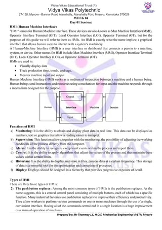
- 1. Vidya Vikas Educational Trust (R), Vidya Vikas Polytechnic 27-128, Mysore - Bannur Road Alanahally, Alanahally Post, Mysuru, Karnataka 570028 Prepared by: Mr Thanmay J.S, H.O.D Mechanical Engineering VVETP, Mysore WEEK 04 Day 01 Session: HMI (Human Machine Interface) "HMI" stands for Human Machine Interface. These devices are also known as Man Machine Interface (MMI), Operator Interface Terminal (OIT), Local Operator Interface (LOI), Operator Terminal (OT), but for the purposes of this guide we will refer to them as HMIs. An HMI is exactly what the name implies: a graphical interface that allows human users to interact with a system's machinery. A Human-Machine Interface (HMI) is a user interface or dashboard that connects a person to a machine, system, or device. Other names for HMI include Man-Machine Interface (MMI), Operator Interface Terminal (OIT), Local Operator Interface (LOI), or Operator Terminal (OT). HMIs are used to: • Visually display data • Track production time, trends, and tags, • Monitor machine input and output Human Machine Interface (HMI) works as a medium of interaction between a machine and a human being. Human beings send instructions and resources using a mechanism for input and the machine responds through a mechanism designed for the purpose. Functions of HMI a) Monitoring: It is the ability to obtain and display plant data in real time. This data can be displayed as numbers, text or graphics that allow a reading easier to interpret. b) Supervision: This function allows, together with the monitoring, the possibility of adjusting the working conditions of the process directly from the computer. c) Alarm: It is the ability to recognize exceptional events within the process and report them d) Control: It is the ability to apply algorithms that adjust the values of the process and thus maintain these values within certain limits. e) Historian: It is the ability to display and store in files, process data at a certain frequency. This storage of data is a powerful tool for the optimization and correction of processes. f) Display: Displays should be designed in a hierarchy that provides progressive exposure of detail. Types of HMI There are three basic types of HMIs: 2) The pushbutton replacer: Among the most common types of HMIs is the pushbutton replacer. As the name suggests, this is a central control panel consisting of multiple buttons, each of which has a specific function. Many industrial factories use pushbutton replacers to improve their efficiency and productivity. They allow workers to perform various commands on one or more machines through the use of a single, convenient interface. Having all of the commands centralized in a single location is a huge improvement over manual operation of machines.
- 2. Vidya Vikas Educational Trust (R), Vidya Vikas Polytechnic 27-128, Mysore - Bannur Road Alanahally, Alanahally Post, Mysuru, Karnataka 570028 Prepared by: Mr Thanmay J.S, H.O.D Mechanical Engineering VVETP, Mysore 3) The data handler: This HMI is primarily used for gathering/harvesting data, at which point it may be sent a hard drive or printed out, depending on the user’s command. Data handlers are particularly useful in applications involving large amounts of data. If a company needs to collect data from a machine or piece of equipment, it will likely use a data handler HMI. 4) The overseer: A third type of HMI is the overseer, which is typically run on the Windows operating system. It takes a more visual approach to the interaction between a human operator and machine, allowing for a graphical interface via an electronic display or touchscreen display. Selection of HMI a) operating environment b) application type 1) The pushbutton replacer: 2) The data handler 3) The overseer c) HMI connect ability d) Data entry and Storage e) Programming software preferences f) Other considerations There are a few other factors to address, such as control options, scalability of programs, geographic location, and technical support. Specifications for HMI a) Number of Devices b) Display Type c) Screen Configuration & Display Size: • Alphanumeric • Graphic d) User Interface Features • Color Display • Touch Screen • Integrated Keypad Interface e) Configuration or Mounting Style • Desktop • Handheld • Panel • Rack • Other Mounting Style f) Processor / CPU Configuration g) CPU Speed h) RAM i) Flash Memory (RAM) j) Hard Drive Capacity k) Other Drive Options l) I/O Interfaces
- 3. Vidya Vikas Educational Trust (R), Vidya Vikas Polytechnic 27-128, Mysore - Bannur Road Alanahally, Alanahally Post, Mysuru, Karnataka 570028 Prepared by: Mr Thanmay J.S, H.O.D Mechanical Engineering VVETP, Mysore • Ethernet • RS232 ~ RS485 • USB • Others m) Features: • Keyboard Support • Networkable System • Meets NEMA Enclosure Standards • Mouse Support • Printer Support • Power Over Ethernet (PoE) • Real Time Clock Support • Software Driver • Speakers Included • Web Enabled n) Applications: • Automotive • Avionics Rated • Military Rated o) Operating Temperature Characteristics or features of an HMI Panel 1) Display size The first consideration is the display size. The panel size starts as small as 3 or 4 inches diagonally, or a larger screen, like 15 or 21 inches. HMI panels come in all sizes, typically from 3 inches to 25 inches. 2) Touchscreen Touchscreens are convenient and allow fast response, but they are more expensive than models with only function and arrow keys. 3) Colour or Monochrome? Colour HMI panels are vivid and allow for status to easily be shown with colours, but monochrome units are less costly and very efficient for showing a small amount of data, like speed feedback or time left in a batch.
- 4. Vidya Vikas Educational Trust (R), Vidya Vikas Polytechnic 27-128, Mysore - Bannur Road Alanahally, Alanahally Post, Mysuru, Karnataka 570028 Prepared by: Mr Thanmay J.S, H.O.D Mechanical Engineering VVETP, Mysore 4) Resolution Screen resolution is required to show sufficient graphic object details or allow display of many objects on the same screen. 5) Mounting About mounting, should HMI be flush mounted in a panel or on a pedestal or be Handheld gives easy access to the control. 6) Protections Protection of HMI control against splashing of liquids or outdoor installation has to be considered. 7) Interfaces Interfaces like Ethernet, Serial interfaces for laboratory instruments, RFI scanners, barcode readers or multiple interfaces has to be considered. 8) Software requirement Every software requires a specialized driver to access data from the controllers 9) Custom program Some HMI terminal has to support plant operations, like barcode software or inventory application interfaces for those custom panels has to be integrated 10) Supports Windows? Some HMI need to support Windows and its file system, or vendor’s HMI application be sufficient.
- 5. Vidya Vikas Educational Trust (R), Vidya Vikas Polytechnic 27-128, Mysore - Bannur Road Alanahally, Alanahally Post, Mysuru, Karnataka 570028 Prepared by: Mr Thanmay J.S, H.O.D Mechanical Engineering VVETP, Mysore Various industry interfaces on HMI panels, a) CUSTOM ELECTRICAL PANEL FABRICATION b) PLC CONTROL PANELS c) HMI CONTROL PANELS d) MOTOR STARTER CONTROL PANELS e) VFD CONTROL PANELS f) PAINT BOOTH CONTROL PANELS g) DUST COLLECTOR PANELS h) TEMPERATURE CONTROL PANELS i) SOLAR BATTERY CONTROL PANEL
- 6. Vidya Vikas Educational Trust (R), Vidya Vikas Polytechnic 27-128, Mysore - Bannur Road Alanahally, Alanahally Post, Mysuru, Karnataka 570028 Prepared by: Mr Thanmay J.S, H.O.D Mechanical Engineering VVETP, Mysore Week 04 Day 02 Session Working with HMI software Tool HMIs are used to communicate with Programmable Logic Controllers and as such, the whole system is completed. Whereas SCADA represents a remote system used to communicate and collect data, HMI is a local machine capable of doing the same thing. But the only difference is, as we said, that HMIs are local machines. The Human-Machine Interface is the user interface that connects the operator to a system, device or machine. An HMI isn’t a particular piece of hardware but rather a screen that allows a user to interact with a device. HMIs can also be called Operator Terminals, Local Operator Interface, Graphical User Interface, etc. If some of these names (OT, LOI, and GUI) sound familiar to you, it’s because you’ve already used some of them. Simply put, HMIs are used for visualization of particular data, for easier understanding and control. SCADA and HMIs are almost the same, yet still different. Both SCADA and HMIs play a huge part in an industrial system that encapsulates them, alongside PLCs. However, they function in a different way. An HMI uses some amount of data and visually represent it, allowing for greater understanding and more efficient supervising process. On the other hand, SCADA systems are focused on control-system operations and they have a huge capacity for data collection. The main advantage of SCADA systems over HMI is that they collect and record information. a) Configure PLC with HMI The HMI unit, depending upon which model you select, will communicate with the PLC using serial communications or by way of an Ethernet connection. HMIs are programmed using free software and via a serial port (USB, or standard DB9 port) available from the vendor. Setup Summary • Connect a serial port from the PC running the HMI programming software (using a USB-DB9 converter device, if required) to the HMI serial port used for programming. • Connect the HMI port for PLC communication to the PLC port used for HMI communication (the HMI has two ports — one for each function). • Run the HMI programming software • Follow the software steps to select the serial port to be used and the type of PLC to be interfaced with. • Export the tag database file from the PLC (if using a tag database) • Import the tag database to the HMI software • Create a new screen with some objects (pushbuttons, switches, LEDs, analog meters, digital meters, etc.) • Assign properties to the screen objects • Save the project file and upload to the HMI display • Test your program by touching a screen object and observing the expected action in the PLC. b) Animation with graphical objects HMI has a powerful Graphical User Interface [GUI] which provides everything you need to design and display comprehensive animated graphics of your process. HMI applications are developed as one or more interactive windows linked together to provide menus, process mimics, status pages etc. Each window can contain ActiveX® Controls, .NET controls, images and built-in HMI drawing elements. The user-friendly interface as well as the powerful graphics tools makes the design of screens fast and easy. Integrated development and run-time environments allow changes to be made on-line without the need to compile or restart. The same mimic can even be opened in design mode and in run time mode at the same time allowing to the modification done in real-time.
- 7. Vidya Vikas Educational Trust (R), Vidya Vikas Polytechnic 27-128, Mysore - Bannur Road Alanahally, Alanahally Post, Mysuru, Karnataka 570028 Prepared by: Mr Thanmay J.S, H.O.D Mechanical Engineering VVETP, Mysore c) Animate objects on an HMI screen to monitor motor status To Animate objects on an HMI screen to monitor motor status. The main requirements will be to control power ON / OFF switch, to control Variable Frequency Drive, to Monitor Motor speed, to Monitor performance in Trend Graph. d) Trend the data of a process parameter using a trend tool. Trends in SCADA / HMI is very useful to track, monitor, calculate, to diagnose useful process parameters from the past saved trend data. You can keep a record of all the process data in the form of a graph, and it is called a trend. Graphical Chart is one of the most convenient methods to view a group of data for anyone to identify the changes taking place instantly by looking at the waveforms. There are two types of Trends, • Real-time trends • Historic trends Real-time Trends As the name explains itself, these are the graphs that display the values of data in real-time and the graph updates for every instant of time we have specified. The above image that the data is getting updated for the time you have mentioned in the update rate. The graph will get updated left to right the old values will get disappeared and new ones will appear in the right. Historical Trends As the name indicates, historic trends are used to display the data in real-time at the same time the old data can be retrieved and viewed on the run time. In Historical Trends, the start time and the end time for which the data you need should be mentioned. The historical for the mentioned time will be displayed on the run time. e) Create user groups and monitor screens with proper authentication. Authentication is the process of identifying users that request access to a system, network, or device. Access control often determines user identity according to credentials like username and password. Other authentication technologies like biometrics and authentication apps are also used to authenticate user identity. 1. Password-based authentication: Passwords are the most common methods of authentication. Passwords can be in the form of a string of letters, numbers, or special characters. To protect yourself you need to create strong passwords that include a combination of all possible options.
- 8. Vidya Vikas Educational Trust (R), Vidya Vikas Polytechnic 27-128, Mysore - Bannur Road Alanahally, Alanahally Post, Mysuru, Karnataka 570028 Prepared by: Mr Thanmay J.S, H.O.D Mechanical Engineering VVETP, Mysore 2. multi-factor authentication: Multi-Factor Authentication (MFA) is an authentication method that requires two or more independent ways to identify a user. Examples include codes generated from the user’s smartphone, Captcha tests, fingerprints, voice biometrics or facial recognition. 3. Certificate-based authentication: Certificate-based authentication technologies identify users, machines or devices by using digital certificates. A digital certificate is an electronic document based on the idea of a driver’s license or a passport. 4. Biometric authentication: Biometrics authentication is a security process that relies on the unique biological characteristics of an individual. Here are key advantages of using biometric authentication technologies: • Biological characteristics can be easily compared to authorized features saved in a database. • Biometric authentication can control physical access when installed on gates and doors. • You can add biometrics into your multi-factor authentication process. 5. Token-based authentication: Token-based authentication technologies enable users to enter their credentials once and receive a unique encrypted string of random characters in exchange. You can then use the token to access protected systems instead of entering your credentials all over again. The digital token proves that you already have access permission. Use cases of token-based authentication include RESTful APIs that are used by multiple frameworks and clients f) Use security features to do tag logging and command execution The Tagname Dictionary dialog box includes separate options to log data and events to the log file. You can set value logging options. For information about setting event logging, see Configuring Alarms in the InTouch® HMI Alarms and Events Guide. For a tag's value to be written to the historical log file, historical logging must be enabled. For more information about setting general logging properties, see Configuring Historical Logging on page 142. For integer and real tags, you can set the Log Deadband in their respective details dialog boxes. The Log Deadband option specifies how many engineering units a tag's value must change to write a log entry. To configure logging for a tag 1. Open the Tagname Dictionary. 2. Select the tag whose data you want saved to the log file. 3. Select Log Data. 4. Select Log Events if you want to log value changes to the tag initiated by an operator, a I/O, Script, or operating system. 5. Click Save and then close the Tagname Dictionary. Added security that can prevents from accidentally running the Synchronizer is by Command Lines. This is accomplished by requiring command line parameters for the program to run, and by requiring the system user to have the Security Synchronizer application feature assigned. Command Execution examples Purpose /Ddomain name Supplies the name of the domain where the Windows groups are located. /L Indicates that the local computer security configuration where the Windows groups are located. /R Indicates that all user accounts not configured to use Windows security will be removed from the security configuration
- 9. Vidya Vikas Educational Trust (R), Vidya Vikas Polytechnic 27-128, Mysore - Bannur Road Alanahally, Alanahally Post, Mysuru, Karnataka 570028 Prepared by: Mr Thanmay J.S, H.O.D Mechanical Engineering VVETP, Mysore Week 04 Day 03 Session Practice Exercise 01: HMI programming involving alarms, trends and bar graphs [Using InTouch] Simple program to alert when water level reaches 50% and plot all the working of slider in Trend. Slider Tag name “Fill” Tank object Expression “Fill” Real Time Treand Configuration
- 10. Vidya Vikas Educational Trust (R), Vidya Vikas Polytechnic 27-128, Mysore - Bannur Road Alanahally, Alanahally Post, Mysuru, Karnataka 570028 Prepared by: Mr Thanmay J.S, H.O.D Mechanical Engineering VVETP, Mysore Practice Exercise 02: Practice control of a Motor through HMI [Using InTouch] Motor OFF Motor ON Component Tag Name On Button On OFF Button Off Motor Rotor R ON indicator AON OFF indicator AOFF Power Supply T InTouch Windows Script IF on == 1 AND off == 0 THEN AON = 1; AOFF = 0; T = T+1; R = T; ENDIF; IF off == 1 THEN AON = 0; AOFF = 1; on = 0; T = 0; R = 0; ENDIF; Note: for Gas coming out give Expression R >= 1
- 11. Vidya Vikas Educational Trust (R), Vidya Vikas Polytechnic 27-128, Mysore - Bannur Road Alanahally, Alanahally Post, Mysuru, Karnataka 570028 Prepared by: Mr Thanmay J.S, H.O.D Mechanical Engineering VVETP, Mysore Week 04 Day 04 Session: Supervisory data control and acquisition system (SCADA) SCADA is “Supervisory Control and Data Acquisition”. Real-time industrial process control systems used to centrally monitor and control remote or local industrial equipment such as motors, valves, pumps, relays, sensors, etc. SCADA is Combination of telemetry and Data Acquisition. SCADA is not just hardware but also software. It’s a concept. It’s a system as a combination of special hardware, software and protocols. SCADA is used to control chemical plant processes, oil and gas pipelines, electrical generation and transmission equipment, manufacturing facilities, water purification and distribution infrastructure, etc. For example, in a SCADA system a PLC can be used to control the flow of cooling water as part of an industrial process. At the same time the supervisor can use the Host control function to set the temperature for the flow of water. It can also have alarms and can record the flow of water temperature and report back to The RTUs and PLCs are responsible for data collection such as meter readings, equipment status etc and communicate back to the SCADA system. This data can be stored in a database for later analysis or monitored by a supervisor to take appropriate actions if required. Concepts of SCADA systems SCADA systems typically implement a distributed database, commonly referred to as a tag database, which contains data elements called tags or points. A point represents a single input or output value monitored or controlled by the system. Points can be either "hard" or "soft". A hard point is representative of an actual input or output connected to the system, while a soft point represents the result of logic and math operations applied to other hard and soft points. Most implementations conceptually remove this distinction by making every property a "soft" point (expression) that can equal a single "hard" point in the simplest case. Point values are normally stored as value-timestamp combinations; the value and the timestamp when the value was recorded or calculated. A series of value-timestamp combinations is the history of that point. It's also common to store additional metadata with tags such as: path to field device and PLC register, design time comments, and even alarming information. SCADA Hardware Functions There are many functions of SCADA; some of them are listed below. Data Collection: collecting of the information via a RTU (remote terminal unit) Data Transfer: transferring it to the central site Data Processing: Carrying out any necessary analysis and control Information Display: Displaying that information on operator screens or displays Control Actions: Required control actions are then conveyed back to the process
- 12. Vidya Vikas Educational Trust (R), Vidya Vikas Polytechnic 27-128, Mysore - Bannur Road Alanahally, Alanahally Post, Mysuru, Karnataka 570028 Prepared by: Mr Thanmay J.S, H.O.D Mechanical Engineering VVETP, Mysore SCADA system essentially has five levels or hierarchies, as listed below 1. Field instrumentation and control devices: These analog and digital sensors situated at each remote site 2. Marshalling terminals and RTUs: These provides an interface to the field devices 3. Communications system: Communications systems form the backbone of SCADA. The widely used systems are wire, fiber optic, radio, telephone line, microwave and possibly even satellite. Specific protocols and error detection techniques are used for efficient and optimum transfer of data pathway for communications between the master station and the remote sites 4. The master station(s): The master stations gather data from the various RTUs provide an operator interface for display of information and control of the remote sites 5. Information Technology (IT) Applications: The commercial information technology (IT) or data processing department computer system. SCADA Protocols A large part of any complex SCADA system design is involved in matching the protocol and communication parameters between connecting devices. There are about 200 such real time user layer and application protocols. These include both proprietary and non- proprietary protocols, some of which are listed below: • Allen Bradley DF1, DH and DH+ • GE Fanuc • Siemens Sinaut • Mitsubishi • Modbus RTU / ASCII • Omron • IEC • Toshiba • Westinghouse • Other Vendor Protocols The industry is now moving away from many of the old and proprietary protocols 1.IEC 60870-5: IEC 60870-5 is the collection of standards produced by the IEC(International Electrotechnical Commission). It was created to provide an open standard for the transmission of SCADA telemetry control and information. It provides a detailed functional description for telecontrol equipment and systems for controlling geographically widespread processes specifically for SCADA systems. The standard is intended for application in the electrical industries, and has data objects that are specifically intended for such applications. It is also applicable to general SCADA applications in any industry. But IEC 60870-5 protocol is primarily used in the electrical industries of European countries. When the IEC 60870-5 was initially completed in 1995 with the publication of the IEC 870-5-101 profile, it covered only transmission over relatively low bandwidth bit-serial communication circuits. With the increasingly widespread use of network communications technology, IEC 60870-5 now also provides for communications over networks using the TCP/IP protocol suite. This same sequence of development occurred for DNP3. 2. DNP3 Protocol: The DNP3 or Distributed Network Protocol is a set of communications protocols used between components in process automation systems. It is usually used is in utilities such as water and electric companies. It is also technically possible to use it in other utilities. It was specifically developed to facilitate communications between various types of data acquisition and control systems. It plays a crucial role in
- 13. Vidya Vikas Educational Trust (R), Vidya Vikas Polytechnic 27-128, Mysore - Bannur Road Alanahally, Alanahally Post, Mysuru, Karnataka 570028 Prepared by: Mr Thanmay J.S, H.O.D Mechanical Engineering VVETP, Mysore SCADA systems. It is used by SCADA Master Stations or Control Centres, Remote Terminal Units, and Intelligent Electronic Devices. It is primarily used for communications between a master station and IEDs or RTU’s. DNP3 supports multiple-slave, peer-to-peer and multiple-master communications. It supports the operational modes of polled and quiescent operation. The latter is also referred to as reporting by exception. The DNP3 protocol is utilized in communication between various SCADA system components. These system components include the SCADA master or HMI, the Remote Terminal Units, and Intelligent Electronic Devices. DNP3 protocol was designed to avoid being distorted by legacy equipment, as well as EMI noise and low-grade transmission channels. While it adds network reliability, the DNP3 protocol does not make provisions for communications security 3.Modbus: The point-to-point Modbus protocol has become a virtual standard for RTU and PLC communications. During communication on a Modbus network, the protocol determines how each controller will know device address, recognize a message addressed to it determine the action to be taken and extract any information / data attached to it. There are a number of expansions to fix these shortcomings. Modbus is, in many companies, a de facto standard in spite of its shortcomings. It cannot, for instance, handle large positive and negative numbers. This has resulted in a number of companies specific expansions of the protocol, such as Bristol, Daniels, ENRON and others. The idea behind Modbus, a command set operating on 16 bit registers has been used by all PLC manufacturers in the past 4.MODBUS X: The non-proprietary Modbus X expansion has been adopted by a number of companies and utilities and by SCADA software suppliers. It fixes the Modbus shortcomings, makes it man readable and able to handle positive and negative numbers with up to 9 digits of resolution, with an exponent range from -99 to +99. Point protocol, designed to read and write to individual I/O (Input Output) points in PLCs on a factory floor. The ModbusX expansion of the protocol is a universal, non-proprietary expansion, which permits handling large process variables in plain ASCII with sign and exponent, capabilities that are missing in Modbus. 5.DNP (Distributed Network Protocol): A member restricted protocol, used in some Electric Power systems. The DNP protocol has gone through various iterations. Presently it is up to version 3.0. The DNP association has rules, which tend to restrict the use of the protocol, and major SCADA software suppliers have been slow in implementing the protocol. 6.ASCII: The dominating computer protocol is ASCII, American Standard Code for Information Interchange. Virtually all computers, printers, modems and many sensors, actuators and flow computers now communicate in ASCII. 7.IEEE 60870: This protocol is mostly used in power transmission and distribution systems IEC 60870-5- 101 is an International Communications Protocol Standard for the Telecontrol of Electric Power transmission systems, which is being widely adopted in many countries throughout the world.
- 14. Vidya Vikas Educational Trust (R), Vidya Vikas Polytechnic 27-128, Mysore - Bannur Road Alanahally, Alanahally Post, Mysuru, Karnataka 570028 Prepared by: Mr Thanmay J.S, H.O.D Mechanical Engineering VVETP, Mysore Application of SCADA SCADA is a system of software and hardware elements that allows industrial organizations to: • Controlling & monitoring Process in real time from Remote location • Analyse & calculation of complex the Process & maintain accordingly the Control Signals • Data Acquisition, Historical Data Logging, Archiving & retrieving • Trend & Alarm generation • Recipe Management for Process & Chemical Industries • Report Generation Applications of SCADA SCADA is widely used in different areas from chemical, gas, water, communications and power systems. The list of applications of SCADA can be listed as follows. a) Electric power system, operation and control: SCADA systems are used in electric power generation plants, transmission area and distribution system. b) Manufacturing Industries or plants: A SCADA helps in management of different inventory items or raw materials, controlling of automated systems in synchronous manner. c) Telecom and IT based systems: Management of different RF based systems, communication mediums and large communication systems including data logging through antennas can be easily done through the SCADA. d) Water and sewage treatment plants and supply management: SCADA based systems are used by the state or municipal corporation to monitor, control and regulate water capacities in reservoir. e) Traffic controls: SCADA helps in regulation of traffic signals, controls the traffic flow in railway systems on road systems and air traffic controls. f) Lift and Elevator controls: SCADA can also be used for lift and elevator controls. g) Buildings, facilities and environments: Facility managers use SCADA to control HVAC, refrigeration units, lighting and entry systems. h) Mass transit and Railway Traction: Transit authorities use SCADA to regulate electricity to subways, trams and trolley buses; to automate traffic signals for rail systems; to track and locate trains and buses; and to control railroad crossing gates. i) SCADA in Power Systems: SCADA is widely used in power systems. The applications for SCADA keep increasing day after day. Some of the applications are • Comprehensive operational planning and control • Fuel resource scheduling • Optimum power flow • Network security • Economic dispatch • Generation dispatch control
- 15. Vidya Vikas Educational Trust (R), Vidya Vikas Polytechnic 27-128, Mysore - Bannur Road Alanahally, Alanahally Post, Mysuru, Karnataka 570028 Prepared by: Mr Thanmay J.S, H.O.D Mechanical Engineering VVETP, Mysore Week 04 Day 05 Session: Developmental Weekly Assessment +Industry Class on HMI and SCADA + Industry Assignment Week 04 Day 06 Session: Industry Class on HMI and SCADA + Industry Assignment