Automation and Robotics Week 07 Theory Notes 20ME51I.pdf
•
0 likes•628 views

Lab Work on PLC Automation simulations Problems Automation and Robotics Solved Problems as per DTE C 20 Syllabus

Recommended
Recommended
More Related Content
What's hot
What's hot (20)
Similar to Automation and Robotics Week 07 Theory Notes 20ME51I.pdf
Similar to Automation and Robotics Week 07 Theory Notes 20ME51I.pdf (20)
More from THANMAY JS
More from THANMAY JS (14)
Recently uploaded
Recently uploaded (20)
Automation and Robotics Week 07 Theory Notes 20ME51I.pdf
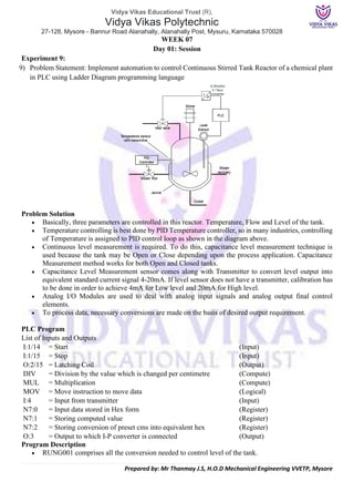
- 1. Vidya Vikas Educational Trust (R), Vidya Vikas Polytechnic 27-128, Mysore - Bannur Road Alanahally, Alanahally Post, Mysuru, Karnataka 570028 Prepared by: Mr Thanmay J.S, H.O.D Mechanical Engineering VVETP, Mysore WEEK 07 Day 01: Session Experiment 9: 9) Problem Statement: Implement automation to control Continuous Stirred Tank Reactor of a chemical plant in PLC using Ladder Diagram programming language Problem Solution • Basically, three parameters are controlled in this reactor. Temperature, Flow and Level of the tank. • Temperature controlling is best done by PID Temperature controller, so in many industries, controlling of Temperature is assigned to PID control loop as shown in the diagram above. • Continuous level measurement is required. To do this, capacitance level measurement technique is used because the tank may be Open or Close depending upon the process application. Capacitance Measurement method works for both Open and Closed tanks. • Capacitance Level Measurement sensor comes along with Transmitter to convert level output into equivalent standard current signal 4-20mA. If level sensor does not have a transmitter, calibration has to be done in order to achieve 4mA for Low level and 20mA for High level. • Analog I/O Modules are used to deal with analog input signals and analog output final control elements. • To process data, necessary conversions are made on the basis of desired output requirement. PLC Program List of Inputs and Outputs I:1/14 = Start (Input) I:1/15 = Stop (Input) O:2/15 = Latching Coil (Output) DIV = Division by the value which is changed per centimetre (Compute) MUL = Multiplication (Compute) MOV = Move instruction to move data (Logical) I:4 = Input from transmitter (Input) N7:0 = Input data stored in Hex form (Register) N7:1 = Storing computed value (Register) N7:2 = Storing conversion of preset cms into equivalent hex (Register) O:3 = Output to which I-P converter is connected (Output) Program Description • RUNG001 comprises all the conversion needed to control level of the tank.
- 2. Vidya Vikas Educational Trust (R), Vidya Vikas Polytechnic 27-128, Mysore - Bannur Road Alanahally, Alanahally Post, Mysuru, Karnataka 570028 Prepared by: Mr Thanmay J.S, H.O.D Mechanical Engineering VVETP, Mysore • Output of transmitter is in current signals which is 4-20mA. • When output is 4mA, Analog Input Module converts it into 16bit equivalent hex numbers. Hence when input at I:3 to Analog module is 4mA, it moves 0000h into register and when 20mA, it moves FFFFh into register. Here register N7:0. • Here height of the tank is 3m or 300cm. By converting it into equivalent hex, change in value per centimetre is 218. • Value of N7:0 is then multiplied with 234 because when Level reaches 280cm, output is 61167 in decimal (EEEFh). So when output at 280cm is multiplied with 234, we get full FFFFh at N7:2 to operate valve to fully close. • This multiplication is stored into N7:2 register. Digital to Analog conversion of value stored in N7:2 is performed inside the processor and equivalent mA current is received from terminal O:3. • Current to Pneumatic converter then converts current signals into equivalent 3-15psi pneumatic signal and adjusts valve opening. Ladder Diagram to control CSTR Runtime Test Cases Inputs Outputs Physical Elements I:4 = 0000h O:3 = 0000h Valve fully open I:4 = EEEFh O:3 = FFFFh Valve fully closed I:4 = 7778h O:3 = 8000h Valve 50% open
- 3. Vidya Vikas Educational Trust (R), Vidya Vikas Polytechnic 27-128, Mysore - Bannur Road Alanahally, Alanahally Post, Mysuru, Karnataka 570028 Prepared by: Mr Thanmay J.S, H.O.D Mechanical Engineering VVETP, Mysore WEEK 07 Day 02: Session Experiment 10: 10) Problem Statement: Water bottles are moved on a conveyor for capping. Screw caps are screwed to close the opening end of the bottle using rotating mechanism. Implement this in PLC using Ladder Diagram programming language Problem Solution • To sense the bottle, proximity sensor is used. • Used a timer to stop the cylinder motor for 2secs to screw caps. • Used one more timer to run the motor for 1sec to rotate the cylinder. • Bit Shift register is also used to perform this operation. • Count the number of steps capping machine is placed from the sensor and set bit position to operate capping machine accordingly. • In this example as you can see, bottle is 7 steps away from the proximity switch, so if Bit register B3:0 is used, then capping machine should be operated when B3:0/0 is shifted to B3:0/6. • Two inputs are given to this Capping machine, electric supply to run motor and pneumatic supply to push machine down cap ram. PLC Program List of Inputs and Outputs I:1/0 = Start (Input) I:1/1 = Stop (Input) I:1.2 = Proximity (Input) O:2/0= Master coil / Run (Output) O:2/1= Cylinder motor (Output) O:2/2= Electric supply to capping machine motor (Output) O:2/3= Pneumatic supply to cap ram (Output) BSL = Bit shift left instruction (Logical) B3:0= Bit shift Register (Register) B3:0/6 = Bit to energize capping machine (Bit) R6:0= Control register (Register) T4:0 = Timer to run cylinder motor (Timer) T4:1 = Timer to stop cylinder motor timer for capping (Timer) LIM = Limit output to perform capping (Compare)
- 4. Vidya Vikas Educational Trust (R), Vidya Vikas Polytechnic 27-128, Mysore - Bannur Road Alanahally, Alanahally Post, Mysuru, Karnataka 570028 Prepared by: Mr Thanmay J.S, H.O.D Mechanical Engineering VVETP, Mysore Program Description • RUNG001, RUNG002 and RUNG003 are used to operate cylinder motor. • Assuming it takes 1.6secs to screw cap a bottle, conveyor is stopped for 2secs and capping is done. • When the system is started, cylinder driving motor with address O:2/1 runs for one 1sec and stops for 2secs. Timer is set to auto reset mode by giving XIO of T4:1/DN in series to it. T4:0 is used to de-energize cylinder driving motor coil with address O:2/1 after 1sec and T4:1 is used to energize the same coil after 2secs. • RUNG004, RUNG005 and RUNG006 are used to operate bit shift register BSL and Capping Machine with address O:2/2. • Whenever proximity sensor with input I:1/2 detects bottle and O:2/1 is energized, I:1/2 sets B3:0/0 bit. This bit is shifted when again this coil is energized. • From proximity to capping machine, distance is 7 steps. Hence bit B3:0/6 of B3:0 register is used to operate capping machine. • Capping machine motor is connected with output O:2/2 which is energized till the process is running. Hence, simply letting master coil run the capping machine motor. • When Accumulator value is between 2 to 18, pneumatic supply is activated and screw capping is operated that is when cylinder motor is stopped for 2secs and timer is between 0.2-1.8secs. Runtime Test Cases Inputs Output Physical Elements I:1/2 = 1 B3:0/0 = 1 Set first bit of bit register O:2/0 = 1 O:2/1 = 1 Start cylinder motor T4:0/DN = 1 O:2/1 = 1 Stop cylinder motor after 2secs T4:1/DN = 1 O:2/1 = 1 Start cylinder motor again T4:0/DN = 0 BSL/EN = 1 Shift bit to left O:2/0 = 1 O:2/2 = 1 Start capping machine motor T4:0.ACC = 2<Accum<16 O:2/3 = 1 Activate pneumatic supply to push down cap ram for capping Ladder diagram to automate screw cap process Ladder Diagram Next Page
- 5. Vidya Vikas Educational Trust (R), Vidya Vikas Polytechnic 27-128, Mysore - Bannur Road Alanahally, Alanahally Post, Mysuru, Karnataka 570028 Prepared by: Mr Thanmay J.S, H.O.D Mechanical Engineering VVETP, Mysore
- 6. Vidya Vikas Educational Trust (R), Vidya Vikas Polytechnic 27-128, Mysore - Bannur Road Alanahally, Alanahally Post, Mysuru, Karnataka 570028 Prepared by: Mr Thanmay J.S, H.O.D Mechanical Engineering VVETP, Mysore WEEK 07 Day 03: Session Experiment 11: 11) Problem Statement: Two tanks have same products filled. Draining from these depends on the requirement from the storage tank. Implement automation in this Drainage tank using with PLC using Ladder Diagram programming language Problem Solution • Level gauge is used to measure level of the storage tank continuously • Level gauge is connected with Level Transmitter which converts corresponding level output in 4- 20mA equivalent. • Analog I/O Modules are chosen to deal with Analog signals. • Centrifugal pumps are used to drain material from both the tanks at the same time. • Two low level switches are used to detect low level of tanks 1 and 2 which turns Pumps OFF when low level is reached. • Height of storage tank is 5meters that is 500cm and the level which is to be maintained is 470cm. • Calculate necessary conversions and use registers to store data and to do arithmetic operations. PLC Program Here is PLC program to Drain Same Products from 2 Tanks, along with program explanation and run time test cases. List of Inputs and Outputs I:1/14 = Start (Input) I:1/15 = Stop (Input) O:2/15 = Mater Coil (Output) I:1/0 = LLS of Tank1 (Input) I:1/1 = LLS of Tank2 (Input) O:3 = Output to I-V converter of Pump1 (Output) O:4 = Output to I-V converter of Pump2 (Output) I:4 = Input to which transmitter is connected (Input) N7:0 = Register to store input data (Register) N7:1 = answer of division by value change per centimeter (Register) N7:2 = Multiplication answer (Register)
- 7. Vidya Vikas Educational Trust (R), Vidya Vikas Polytechnic 27-128, Mysore - Bannur Road Alanahally, Alanahally Post, Mysuru, Karnataka 570028 Prepared by: Mr Thanmay J.S, H.O.D Mechanical Engineering VVETP, Mysore Program Description • RUNG001 comprises all the conversion needed to control pumps. • Output of transmitter is in current signals which is 4-20mA. • When output is 4mA, Analog Input Module converts it into 16bit equivalent hex numbers. Hence when input at I:3 to Analog module is 4mA, it moves 0000h into register and when 20mA, it moves FFFFh into register. Here register N7:0. • Here height of the tank is 5m or 500cm. By converting it into equivalent hex, change in value per centimetre is 132. • Value of N7:0 is then multiplied with 139 because when Level reaches 470cm, output is F0C0h. So, when output at 470cm is multiplied with 139, we get full FFFFh at N7:2 to operate pumps in full speed. • This multiplication is stored into N7:2 register. Digital to Analog conversion of value stored in N7:2 is performed inside the processor and equivalent mA current is received from terminal O:3 and O:4. • Current to Voltage converter then converts current signals into voltage signal and adjusts motor speed. • Two pumps are used here hence speed of response is very good and smooth operation is achieved. Reset operation to turn off Pumps when low level is detected • Both tanks have a Low-Level switch at the bottom. When there is no material in the tank or very less material is present, pump should not run-in order to prevent it from failure. Limit switch with address I:1/0 is for tank1 and I:1/1 is for tank2. Runtime Test Cases Inputs Outputs Physical Elements I:4 = F258h O:3 = O:4 = 0000h Pump1 and Pump2 are off I:4 = 792Ch O:3 = O:4 = 8000h Pump1 and Pump2 = 4000RPM I:4 = 50C8h O:3 = O:4 = 5474h Pump1 and Pump2 = 2640RPM I:1/0 = 1 O:3 = 0000h Pump1 off I:1/1 = 1 O:4 = 0000h Pump2 off Ladder diagram to Draining two tanks process Ladder Diagram Next Page
- 8. Vidya Vikas Educational Trust (R), Vidya Vikas Polytechnic 27-128, Mysore - Bannur Road Alanahally, Alanahally Post, Mysuru, Karnataka 570028 Prepared by: Mr Thanmay J.S, H.O.D Mechanical Engineering VVETP, Mysore
- 9. Vidya Vikas Educational Trust (R), Vidya Vikas Polytechnic 27-128, Mysore - Bannur Road Alanahally, Alanahally Post, Mysuru, Karnataka 570028 Prepared by: Mr Thanmay J.S, H.O.D Mechanical Engineering VVETP, Mysore WEEK 07 Day 04: Session Experiment 12: 12) Problem Statement: Potato chips are made and ready to be packed. But before that, it goes through a conveyor in which final quality check is done, burnt chips are detected and removed from the process line. Implement this in PLC using Ladder Diagram programming language Problem Solution • To detect burned chips, light source and sensors are used. • Light source is used so light detectors such as Light Dependent Resistors are used to detect the burned chips. • Blowers are used to throw burned chips away from the conveyor when detected. • There are total number of 8 blowers. Number of blowers to be used depends on the width of a conveyor belt. • Time measurement of an event to take place can be used here to measure what time burned chips take to reach from light source to blowers when detected. • Set this time as preset of a timer to operate particular blower. • There are 8 blowers, so 8 light detecting circuits must be used in order to operate all blowers. • Let us assume we are using Light Dependent Resistor. To use this resistor, threshold has to be set that is darkest color to be passed as a good quality product. If chips are darker than the desired level, light source detects it and activates corresponding circuit. • So output of this circuit is normally high and to activate blower, normally low logic has to be set while programming or we can even invert output from LDR circuit. PLC Program Here is PLC program to Detect Burned Chips and Remove them, along with program explanation and run time test cases. List of Inputs and Outputs I:1/14 = Start (Input) I:1/15 = Stop (Input) O:2/15 = Master Coil (Input) O:2/8 = Conveyor (Output) O:2/9 = Light Source (Output) I:1/0 to I:1/7= Light Dependent Resistors (Input) B3:0/0 to B3:0/7 = Bit latching (Bits) O:2/0 to O:2/7= Blowers (Output) T4:0 = Timer to activate blower after 1sec (Timer)
- 10. Vidya Vikas Educational Trust (R), Vidya Vikas Polytechnic 27-128, Mysore - Bannur Road Alanahally, Alanahally Post, Mysuru, Karnataka 570028 Prepared by: Mr Thanmay J.S, H.O.D Mechanical Engineering VVETP, Mysore Program Description • RUNG001 operates conveyor and light source. When Start PB is pressed, it energizes conveyor motor coil and light source. • There is total 8 LDR circuits are mounted next to each other. LDR1 activates Blower1, LDR2 activates Blower2 and so on. • Ladder diagram has shown just two LDRs and Blowers. Further programming for all other blowers and LDRs remains same. • When any defected part is detected, for example if LDR1 detects a defected part, then it latches the corresponding coil bit B3:0/0 which in turn activates timer. • 1sec is assumed time taken by a part to reach from Light Source to Blower and hence timer has preset 10. • When 1sec is over, it activates Blower1 with address O:2/0. Blower energizes and immediately de- energizes giving just a push to detected part. • Similarly, it works for all LDR circuits. • Many PLCs provide Time Base of 0.01 which may be used for more accuracy. Runtime Test Cases Inputs Outputs Physical Elements I:1/14 = 1 O:2/8 = O:2/9 = 1 Run conveyor and turn ON lights I:1/0 = 1 & T4:0/DN = 1 O:2/0 = 1 (Momentarily) Blower1 energizes momentarily I:1/1 = 1 & T4:0/DN = 1 O:2/1 = 1 (Momentarily) Blower2 energizes momentarily Ladder diagram to accomplish quality control by removing defected chips Ladder Diagram Next Page
- 11. Vidya Vikas Educational Trust (R), Vidya Vikas Polytechnic 27-128, Mysore - Bannur Road Alanahally, Alanahally Post, Mysuru, Karnataka 570028 Prepared by: Mr Thanmay J.S, H.O.D Mechanical Engineering VVETP, Mysore
- 12. Vidya Vikas Educational Trust (R), Vidya Vikas Polytechnic 27-128, Mysore - Bannur Road Alanahally, Alanahally Post, Mysuru, Karnataka 570028 Prepared by: Mr Thanmay J.S, H.O.D Mechanical Engineering VVETP, Mysore WEEK 07 Day 05: Session CIE 3– Written and practice test + Assessment Review and corrective action WEEK 07 Day 06: Session Industry Class on Automation in process Industry + Industry Assignment