Automation and Robotics Week 08 Theory Notes 20ME51I.pdfTHANMAY JS
Day 01 Session:
Concepts of Industrial Robots, Applications of Robotics, Types of robots,
Configurations of robots – Articulated Robot, Polar configuration, SCARA,
Cartesian Co-ordinate Robot, Delta Robot, Key Components of Robot.
Day 02 Session:
Wrist configuration, Work Volume Degree of Freedom- Forward and Back, Up and Down, Left and Right,
Pitch, Yaw, Roll, Joint Notation & Type of joints in robot- Linear Joint (L Joint), Orthogonal Joint (O Joint),
Rotational Joint (R Joint), Twisting Joint (T Joint), Revolving Joint (V Joint)
End Effectors- Grippers, Tools, Types of grippers, Factors to be considered for Selecting a Gripper,
Robotic Drives- Electric Drive, Pneumatic Drive, Hydraulic Drive
Day 03 Session:
Robot Control systems-
• Point- to Point control Systems
• Continuous Path Control
• Intelligent control
• Controller Components
• System Control
Robotic Coordinate system using a robot
• Joint co-ordinate system
• Rectangular co-ordinate system
• User or object coordinate system
• Tool coordinate system.
Steps to define user co-ordinate system.
• Defining X, Y, Z co-ordinate system
• Verifying co-ordinate system by multiple motion movements.
Automation and Robotics Week 03 Theory Notes 20ME51I.pdfTHANMAY JS
Day 01 Session:
Explain and demonstrate how to establish communication network with PLC systems using industry standard
communication protocols for data transfer
• Serial Communications
• ASCII Functions
• Parallel Communications
Day 02 Session:
Explain and demonstrate different types of networking architecture
Explain OSI model of networking
Networking hardware
Demonstrate TCP/IP Protocol, Introduction to IP Address, Subnet Mask,
Networking Devices, Network topology
Day 03 Session:
Industrial Automation Communication Protocols - RS232-422-485 standards
Network standards, Modbus, CAN bus, ControlNet, Ethernet, Profibus, FIP I/O, Static and Dynamic Routing
principle
Day 04 Session:
Concepts of Wireless Networking
Latest trends in PLC communication protocols.
Fundamental Parts and Characteristics of PLC communication Protocol
Demonstrate Peer to Peer (PLC to PLC) & PLC to PC Communication protocols
Automation and Robotics Week 04 Theory Notes 20ME51I.pdfTHANMAY JS
Working with HMI software Tool
• Configure PLC with HMI
• Animation with graphical objects
• Animate objects on an HMI screen to
monitor motor status
• Trend the data of a process parameter
using a trend tool.
• Create user groups and monitor
screens with proper authentication.
• Use security features to do tag logging
and command execution
Automation and Robotics Week 02 Theory Notes 20ME51I.pdfTHANMAY JS
WEEK 02
Day 01 Session:
Recap and Practice PLC Ladder Diagram for Logic Gates, Timers, Counters
Day 02 Session:
Explain and Practice PLC Ladder Diagram for Compare, Jump and Subroutines
Explain and Practice PLC Ladder Diagram for Math Instructions and Shift Registers
Day 03 Session:
Explain and Practice PLC Program using Functional Block Diagram
Day 04 Session:
Explain and Practice PLC Program using Structural Text language
Automation and Robotics Week 01 Theory Notes 20ME51I.pdfTHANMAY JS
Identify the possibilities of automation in a production system Discuss Hierarchy of Industrial Automation,
Industrial Automation pyramid. Present an Overview on the Levels of Automation-
• Device level
• Machine Level
• Cell Level
• Plant Level
• Enterprise Level
Automation and Robotics Lab Manual 20ME51I.pdfTHANMAY JS
Automation and Robotics 20ME51I DTE C 20 Syllabus Programme Specialization Pathway
DTE 5th semester; DTE Karnataka C 20; 5th Semester Mechanical Engineering [General]
PLC Circuits; PLC Ladder Diagram; RSLogix 500; Identify the possibilities of automation in a production system; Select the Hardware components required for Automation and establish communication network by using industry standard protocol; Develop, simulate, interface and Execute an Automation system for a given Application; Develop, simulate, interface and Execute Robot Program for a specified process in an Automation system; Integrate HMI, SCADA and IIOT in an automation system
Elements of Industrial Automation 20ME43P C-20 Lab Manual.pdfTHANMAY JS
Experiment 01: Activation of Various Output Indicator Elements using Push buttons
Experiment 02: Activation of Indicator Light by series and Parallel switches
Experiment 03: Activation of Indicator Light by Coil activated Contact Switch
Experiment 04: Activating Indicator light using Circuit with Coil latch and Coil Unlatch
Experiment 05: Activation of Indicator light by Delay timer circuit
Experiment A: Control of double acting cylinder using Proximity sensors and Proximity Switch
Experiment B: Control of double acting cylinder using delay on and off timer and counter
Experiment C: Execute energized motor using Switches in Series or Parallel Circuit
Experiment D: Execute energized motor using Switches in Latching Circuit
Experiment E: Execute energized motor using Switches in Sequential O/P
Experiment F: Delay Control of Motors using Timer function
Experiment G: Control of Motors using Relay contact
Experiment H: Indirect Control of Forward and Reverse motion in Motor
Experiment I: Direct Control of Forward and Reverse motion in Motor
Material handling (MH) makes use of the robot's simple capability to transport objects. By fitting the robot with an appropriate end of arm tool (e.g. gripper), the robot can efficiently and accurately move product from one location to another.
Robot is a Machine designed to execute one or more tasks automatically by means of variable programmed motions with high speed and precision.
Elements of Industrial Automation Week 08 Notes.pdfTHANMAY JS
Select a suitable Sensor / Switch for a given Process Variable and activate
• Selection of Sensor/Transducer – 10 Marks
• Activation and Result –20Marks
OR
Select a suitable motor for the given case and energize
• Selection of the Motor – 10 Marks
• Energize and Result – 20 Marks
Device and Simulate a ladder diagram for the given Case Study
• Writing Ladder Program –30 Marks
• Simulate and Troubleshoot –20 Marks
Elements of Industrial Automation Week 06 Notes.pdfTHANMAY JS
Select a suitable Sensor / Switch for a given Process Variable and activate
• Selection of Sensor/Transducer – 10 Marks
• Activation and Result –20Marks
OR
Select a suitable motor for the given case and energize
• Selection of the Motor – 10 Marks
• Energize and Result – 20 Marks
Device and Simulate a ladder diagram for the given Case Study
• Writing Ladder Program –30 Marks
• Simulate and Troubleshoot –20 Marks
Elements of Industrial Automation Week 07 Notes.pdfTHANMAY JS
Select a suitable Sensor / Switch for a given Process Variable and activate
• Selection of Sensor/Transducer – 10 Marks
• Activation and Result –20Marks
OR
Select a suitable motor for the given case and energize
• Selection of the Motor – 10 Marks
• Energize and Result – 20 Marks
Device and Simulate a ladder diagram for the given Case Study
• Writing Ladder Program –30 Marks
• Simulate and Troubleshoot –20 Marks
Elements of Industrial Automation Week 09 Notes.pdfTHANMAY JS
Select a suitable Sensor / Switch for a given Process Variable and activate
• Selection of Sensor/Transducer – 10 Marks
• Activation and Result –20Marks
OR
Select a suitable motor for the given case and energize
• Selection of the Motor – 10 Marks
• Energize and Result – 20 Marks
Device and Simulate a ladder diagram for the given Case Study
• Writing Ladder Program –30 Marks
• Simulate and Troubleshoot –20 Marks
Solar powered illumination with maximum power point tracking MPPT by Anoop ku...Anoop kumar Niravuparambil
The installation of photovoltaic (PV) generation systems is rapidly growing in response to concerns related to energy security and environmental issues such as global warming. PV generation system is considered as a clean and environmentally-friendly source of energy. However, PV generation systems have two major problems which are related to low conversion efficiency of about 15 to 20 % especially in low irradiation conditions and that the amount of electric power generated by PV arrays varies continuously with weather conditions. Thus there is a need for an efficient tool for maximizing the power produced from the PV panel. Here comes the role of Maximum Power point Tracking (MPPT) technology.
The MPPT is an instrument that extract maximum power available from the PV array at any given instant. Basically there are two type of MPPT techniques.
(i) Mechanical Tracking
(ii) Electronic tracking
In mechanical tracking,
In electronic tracking, MPPT controller is employed, which is an electronic charge controller system is used to track the maximum power point of PV systems. The power available from a PV module passes through a peak at a particular operating point, and this peak is also changes with atmospheric conditions. Hence the change in peak power needs to be continuously tracked. Electronic MPPT system thus uses a DC to DC converter as the MPPT controller, which introduced between the source and load in
order to nullify the load mismatch conditions. This is done by varying the duty cycle of the charge controller in such a way to optimize the current drawn from the array.
Charge controllers are generally employed with tracking algorithms. Perturb and observe (P & O) method, Incremental conductance (IC) and Hybrid tracking methods are some example of algorithms used in MPPT. Since the ease in digitalized programming and less complicate when compared with other algorithms, P & O algorithm is preferred in this project. P & O method involve perturbing the point (voltage) of operation and measuring the power delivered by the PV array. This process followed by comparing the power values at two consecutive instant that leads to decision on the direction of perturbation in the subsequent sampling cycle.
This is a report regarding an industrial training done by me at Rosa Power Supply Ltd. which is a 1200 MW(4X300 MW) thermal power plant owned by Reliance Power.
In this paper, we propose a new technique for implementing optimum controller for a conical tank. The objective of the controller is to maintain the level inside the process tank in a desired value. Hence an attempt is made in this paper as Internal Model Based PID controller design for conical tank level control. For each stable operating point, a first order process model was identified using process reaction curve method. The real time implementation is done in Simulink using MATLAB. The experimental results shows that proposed control scheme have good set point tracking and disturbance rejection capability.
YEAR /SEM: IV/VII
SUBJECT / CODE: MECHATRONICS ME8791
Part – A (5x2 = 10)
1. What are the basic elements of the
Measurement system and sketch its
Block diagram?
2. Draw the basic feedback (Closed Loop)
System & indicate various terms associated
with block diagram.
3. How do classify the Sensors?
4. Give an example for a Transducer and state
Its transduction principles.
5. Draw the open loop system & indicate
Various terms associated with block diagram.
Part B (2x 10 = 20)
6. Explain about Automatic control system
With a block diagram.
7. Explain the concept of Mechatronics
Approach with neat sketch?
Similar to Automation and Robotics Week 05 Theory Notes 20ME51I.pdf (20)
Fundamentals of Automation Technology 20EE43P Portfolio.pdfTHANMAY JS
Course Outcome:
CO01 Select a suitable sensor and actuator for a given automation application and demonstrate its use.
CO02 Install, test & control the pneumatic actuators using various pneumatic valves.
CO03 Develop ladder diagrams for a given application and explain its implementation using PLC.
CO04 Describe the concept of SCADA and DCS systems and list their various applications
Fundamentals of Computer 20CS11T Chapter 5.pdfTHANMAY JS
Chapter 05: INTRODUCTION TO COMPUTER PROGRAMMING
5.1 Basics of programming
• Algorithms and Flowcharts
• Basics
• Decision making
• Iterative
(With sufficient examples)
5.2 Programming Languages
• Generation of languages
• General concepts of variables and constants
Fundamentals of Computer 20CS11T Chapter 4.pdfTHANMAY JS
Chapter 04: INTRODUCTION TO COMPUTER ORGANIZATION & OPERATING SYSTEM
4.1 Introduction
• Overview of functional units of a computer
• Stored Program Concept
• Flynn's Classification of Computers
4.2 Memory Hierarchy
• Main memory
• Auxiliary memory
• Cache memory
4.3 Introduction to BIOS and UEFI
4.4 OS Concepts
• Overview
• Types (Batch Operating System, Multitasking/Time Sharing OS, Multiprocessing OS, Real Time OS, Distributed OS, Network OS, Mobile OS)
• Services
1.1 Introduction to number system.
• Decimal • Binary • Octal • Hexadecimal • Characteristics of each number system
1.2 Conversion from one number system to other
1.3 Complements of number systems and arithmetic operations
1.4 Computer codes (BCD, EBCDIC, ASCII Code, Gray code, Excess-3 code and Unicode)
1.5 Logic gates
1.6 Boolean algebra (rules, laws, De-Morgan Theorem, Boolean expressions and simplifications)
Solved Question Papers
Elements of Industrial Automation Week 05 Notes.pdfTHANMAY JS
Select a suitable Sensor / Switch for a given Process Variable and activate
• Selection of Sensor/Transducer – 10 Marks
• Activation and Result –20Marks
OR
Select a suitable motor for the given case and energize
• Selection of the Motor – 10 Marks
• Energize and Result – 20 Marks
Device and Simulate a ladder diagram for the given Case Study
• Writing Ladder Program –30 Marks
• Simulate and Troubleshoot –20 Marks
Elements of Industrial Automation Week 04 Notes.pdfTHANMAY JS
Select a suitable Sensor / Switch for a given Process Variable and activate
• Selection of Sensor/Transducer – 10 Marks
• Activation and Result –20Marks
OR
Select a suitable motor for the given case and energize
• Selection of the Motor – 10 Marks
• Energize and Result – 20 Marks
Device and Simulate a ladder diagram for the given Case Study
• Writing Ladder Program –30 Marks
• Simulate and Troubleshoot –20 Marks
Elements of Industrial Automation Week 03 Notes.pdfTHANMAY JS
Select a suitable Sensor / Switch for a given Process Variable and activate
• Selection of Sensor/Transducer – 10 Marks
• Activation and Result –20Marks
OR
Select a suitable motor for the given case and energize
• Selection of the Motor – 10 Marks
• Energize and Result – 20 Marks
Device and Simulate a ladder diagram for the given Case Study
• Writing Ladder Program –30 Marks
• Simulate and Troubleshoot –20 Marks
Elements of Industrial Automation Week 02 Notes.pdfTHANMAY JS
Select a suitable Sensor / Switch for a given Process Variable and activate
• Selection of Sensor/Transducer – 10 Marks
• Activation and Result –20Marks
OR
Select a suitable motor for the given case and energize
• Selection of the Motor – 10 Marks
• Energize and Result – 20 Marks
Device and Simulate a ladder diagram for the given Case Study
• Writing Ladder Program –30 Marks
• Simulate and Troubleshoot –20 Marks
Elements of Industrial Automation Week 01 Notes.pdfTHANMAY JS
Select a suitable Sensor / Switch for a given Process Variable and activate
• Selection of Sensor/Transducer – 10 Marks
• Activation and Result –20Marks
OR
Select a suitable motor for the given case and energize
• Selection of the Motor – 10 Marks
• Energize and Result – 20 Marks
Device and Simulate a ladder diagram for the given Case Study
• Writing Ladder Program –30 Marks
• Simulate and Troubleshoot –20 Marks
Fundamentals of Automation Technology 20EE43P C-20 Lab Manual SCADA.pdfTHANMAY JS
1.Meaning of SCADA
-Functions of each component of SCADA system,
-Describe SCADA Hardware and software
-Applications of SCADA.
Experiment 01: Moving of Object from one Place to Another
Experiment 02: Filling up of Tank
Experiment 03: Lighting a Bulb
Experiment 04: Starting of Fan
Fundamentals of Automation Technology 20EE43P C-20 Lab Manual.pdfTHANMAY JS
For a given automation application select suitable pneumatic components and sensors.
Experiment 01: Electro pneumatics circuits for Direct Control of single acting cylinder
Experiment 02: Electro pneumatics circuits for In-Direct Control of single acting cylinder
Experiment 03: Electro pneumatics circuits for Direct Control of Double acting cylinder
Experiment 04: Electro pneumatics circuits for In-Direct Control of Double acting cylinder
Experiment 05: Electro pneumatics circuits for Control of Actuator using OR logic (Parallel circuit)
Experiment 06: Electro pneumatics circuits for Control of Actuator using AND logic (Series circuit)
Experiment 07: Electro pneumatics circuits for Automatic return of a Single acting cylinder
Experiment 08: Oscillation of double acting cylinder using proximity switches and Double Solenoid Sensors
Experiment 09: Control of double acting cylinder using pressure switch
Experiment 10: Control of double acting cylinder using delay timer
Section B
Demonstrate & control the Pneumatic actuators using pneumatic valves.
Experiment A: Conveyor belt with Oscillation motion
Experiment B: Latching circuit with a limit switch and Mechanical Position sensor
Experiment C: Simultaneous Transfer station Simulation Circuit
Experiment D: Multiple actuator circuit with direct control circuit
Experiment E: Stamping Circuit using Delay timer switch
Product Design and Development 20ME43P C-20 Lab Manual.pdfTHANMAY JS
Product Development and Design:
1. Explain Product Development-Stages of Product Development-Need and Feasibility study
2. Explain Development of design-Selection of Materials and Process
3. Explain Protype –launching of product –Product life cycle
General consideration in design Based on:
• Functional requirement
• Effect on environment
• Life, Reliability, Safety
• Principles of Standardization
• Assembly Feasibility
• Maintenance-Cost-Quantity
• Legal issues and Patents
• Aesthetic and Ergonomic factors
• Choice of Materials
• Feasibility of Manufacturing Processes
Aesthetic and Ergonomic consideration in Design:
• Explain Aesthetic considerations-Basic types of product forms, designing for appearance, shape, Design features, Materials, Finishes, proportions, Symmetry Contrast etc.
• Morgan’s color code.
• Ergonomic considerations-Relation between man, machine and environmental factors.
• Design of displays and controls.
“Case Study on Ergonomics and Aesthetic design principles”.
Torsion of Shaft:
1. Assumptions in Shear stress in a shaft subjected to torsion –Strength and Rigidity (Solid and Hollow shaft)
2. Power Transmitted by Solid and Hollow shaft - ASME and BIS Code for power Transmission
3. Problems on Shafts subjected to only Shear based on Rigidity and Strength
Validate the Problems on Shafts for Strength and Rigidity using Ansys (One each on Strength and Rigidity)
1. Problems on Shafts subjected to only Shear based on Rigidity and Strength
2. Problems on Shaft subjected to only Bending
3. Problems on Shaft subjected to only Bending
Practice on Section of Solids
a) Prisms
b) Pyramid
1. Problems on Shaft subjected to combined Shear and Bending.
2. Problems on Shaft subjected to combined Shear and Bending
3. Problems on Shaft subjected to combined Shear and Bending
Practice on Section of Solids
a) Cylinder
b) Cone
Springs:
1. Classification of springs- Application of springs- Leaf springs –Application
2. Terminology of Helical spring-Materials and Specification of springs
3. Design of helical spring
Sections on Simple Machine Elements (CAD)
a) Sectional front view, Front view with Right half in Section, Front view with Left half in Section
b) Sectional Top View
c) Sectional Side View
Coupling:
i. Design of Muff coupling
ii. Design of Protected type Flange Coupling
iii. Design of Knuckle Joint
Using CAD, prepare Part Models for Muff coupling based on designed parameter and assemble the same.
Extract the Sectional views for the above machine element indicating Surface Texture and Bill of Materials
3D Printing
1. Introduction, Process, Classifications, Advantages of additive over conventional Manufacturing, Applications, Modeling for Additive Manufacturing
2. Additive Manufacturing Techniques, 3D Printing Materials and its forms, Post Processing Requirement and Techniques.
3. Product Quality, Inspection and Testing, Defects and their causes, Additive Manufacturing Application Domains
Preparation of 3D Printer for printing – Modeling, S
Contents
I. Introduction to “computer aided analysis and simulation”.
II. Basic Tools / Commands used in ANSYS
III. Basics of Shear Force and Bending Moment Calculation
PART -I
A) Stress Analysis of Bars of Constant Cross Section Area
1. Determine the nodal displacement, stress in each element and reaction forces of bar
subjected to a Tensile force.
2. Determine the nodal displacement, stress in each element and reaction forces of bar
subjected to a Compression force.
B) Stress Analysis of Bars Varying In Cross Section or Stepped Bars
1. Determine the nodal displacement, stress in each element and reaction forces of Stepped
bar subjected to an external load.
C ) Stress Analysis of Bars of Tapered Cross Section Area
1. Determine the nodal displacement, stress in each element and reaction forces of Taper
bar subjected to a external loads.
D) Special Problems by Variations
PART-II
E) Stress analysis of Beams
1. Draw the shear force and bending moment diagrams for the given Cantilever beam due
to applied load.
2. Draw the shear force and bending moment diagrams for the given Simply supported
beam due to central point load
3. Draw the shear force and bending moment diagrams for the given Simply supported
beam due to UDL
4. Draw the shear force and bending moment diagrams for the given Simply supported
beam due to applied load (one point loads, and UDL)
5. Draw the shear force and bending moment diagrams for the given Simply supported
beam due to Uniformly varying load (UVL)
6. Draw the shear force and bending moment diagrams for the given Simply supported
beam due to applied load (Several point loads, UVL)
F) Stress Analysis of a Rectangular Plate with a circular Hole
1. Determine the stress acting on a rectangular plate with a circular hole due to the applied
external load
G) Special Problems using Variations
Normal Labour/ Stages of Labour/ Mechanism of LabourWasim Ak
Normal labor is also termed spontaneous labor, defined as the natural physiological process through which the fetus, placenta, and membranes are expelled from the uterus through the birth canal at term (37 to 42 weeks
How to Make a Field invisible in Odoo 17Celine George
It is possible to hide or invisible some fields in odoo. Commonly using “invisible” attribute in the field definition to invisible the fields. This slide will show how to make a field invisible in odoo 17.
A Strategic Approach: GenAI in EducationPeter Windle
Artificial Intelligence (AI) technologies such as Generative AI, Image Generators and Large Language Models have had a dramatic impact on teaching, learning and assessment over the past 18 months. The most immediate threat AI posed was to Academic Integrity with Higher Education Institutes (HEIs) focusing their efforts on combating the use of GenAI in assessment. Guidelines were developed for staff and students, policies put in place too. Innovative educators have forged paths in the use of Generative AI for teaching, learning and assessments leading to pockets of transformation springing up across HEIs, often with little or no top-down guidance, support or direction.
This Gasta posits a strategic approach to integrating AI into HEIs to prepare staff, students and the curriculum for an evolving world and workplace. We will highlight the advantages of working with these technologies beyond the realm of teaching, learning and assessment by considering prompt engineering skills, industry impact, curriculum changes, and the need for staff upskilling. In contrast, not engaging strategically with Generative AI poses risks, including falling behind peers, missed opportunities and failing to ensure our graduates remain employable. The rapid evolution of AI technologies necessitates a proactive and strategic approach if we are to remain relevant.
The French Revolution, which began in 1789, was a period of radical social and political upheaval in France. It marked the decline of absolute monarchies, the rise of secular and democratic republics, and the eventual rise of Napoleon Bonaparte. This revolutionary period is crucial in understanding the transition from feudalism to modernity in Europe.
For more information, visit-www.vavaclasses.com
June 3, 2024 Anti-Semitism Letter Sent to MIT President Kornbluth and MIT Cor...Levi Shapiro
Letter from the Congress of the United States regarding Anti-Semitism sent June 3rd to MIT President Sally Kornbluth, MIT Corp Chair, Mark Gorenberg
Dear Dr. Kornbluth and Mr. Gorenberg,
The US House of Representatives is deeply concerned by ongoing and pervasive acts of antisemitic
harassment and intimidation at the Massachusetts Institute of Technology (MIT). Failing to act decisively to ensure a safe learning environment for all students would be a grave dereliction of your responsibilities as President of MIT and Chair of the MIT Corporation.
This Congress will not stand idly by and allow an environment hostile to Jewish students to persist. The House believes that your institution is in violation of Title VI of the Civil Rights Act, and the inability or
unwillingness to rectify this violation through action requires accountability.
Postsecondary education is a unique opportunity for students to learn and have their ideas and beliefs challenged. However, universities receiving hundreds of millions of federal funds annually have denied
students that opportunity and have been hijacked to become venues for the promotion of terrorism, antisemitic harassment and intimidation, unlawful encampments, and in some cases, assaults and riots.
The House of Representatives will not countenance the use of federal funds to indoctrinate students into hateful, antisemitic, anti-American supporters of terrorism. Investigations into campus antisemitism by the Committee on Education and the Workforce and the Committee on Ways and Means have been expanded into a Congress-wide probe across all relevant jurisdictions to address this national crisis. The undersigned Committees will conduct oversight into the use of federal funds at MIT and its learning environment under authorities granted to each Committee.
• The Committee on Education and the Workforce has been investigating your institution since December 7, 2023. The Committee has broad jurisdiction over postsecondary education, including its compliance with Title VI of the Civil Rights Act, campus safety concerns over disruptions to the learning environment, and the awarding of federal student aid under the Higher Education Act.
• The Committee on Oversight and Accountability is investigating the sources of funding and other support flowing to groups espousing pro-Hamas propaganda and engaged in antisemitic harassment and intimidation of students. The Committee on Oversight and Accountability is the principal oversight committee of the US House of Representatives and has broad authority to investigate “any matter” at “any time” under House Rule X.
• The Committee on Ways and Means has been investigating several universities since November 15, 2023, when the Committee held a hearing entitled From Ivory Towers to Dark Corners: Investigating the Nexus Between Antisemitism, Tax-Exempt Universities, and Terror Financing. The Committee followed the hearing with letters to those institutions on January 10, 202
Automation and Robotics Week 05 Theory Notes 20ME51I.pdf
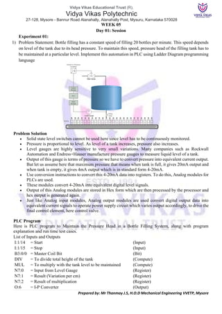
1. Vidya Vikas Educational Trust (R),
Vidya Vikas Polytechnic
27-128, Mysore - Bannur Road Alanahally, Alanahally Post, Mysuru, Karnataka 570028
Prepared by: Mr Thanmay J.S, H.O.D Mechanical Engineering VVETP, Mysore
WEEK 05
Day 01: Session
Experiment 01:
1) Problem Statement: Bottle filling has a constant speed of filling 20 bottles per minute. This speed depends
on level of the tank due to its head pressure. To maintain this speed, pressure head of the filling tank has to
be maintained at a particular level. Implement this automation in PLC using Ladder Diagram programming
language
Problem Solution
• Solid state level switches cannot be used here since level has to be continuously monitored.
• Pressure is proportional to level. As level of a tank increases, pressure also increases.
• Level gauges are highly sensitive to very small variations. Many companies such as Rockwall
Automation and Endress+Hauser manufacture pressure gauges to measure liquid level of a tank.
• Output of this gauge is terms of pressure so we have to convert pressure into equivalent current output.
But let us assume here that maximum pressure that means when tank is full, it gives 20mA output and
when tank is empty, it gives 4mA output which is in standard form 4-20mA.
• Use conversion instructions to convert this 4-20mA data into registers. To do this, Analog modules for
PLCs are used.
• These modules convert 4-20mA into equivalent digital level signals.
• Output of this Analog modules are stored in Hex form which are then processed by the processor and
hex output is generated again.
• Just like Analog input modules, Analog output modules are used convert digital output data into
equivalent current signals to operate power supply circuit which varies output accordingly, to drive the
final control element, here control valve.
PLC Program
Here is PLC program to Maintain the Pressure Head in a Bottle Filling System, along with program
explanation and run time test cases.
List of Inputs and Outputs
I:1/14 = Start (Input)
I:1/15 = Stop (Input)
B3:0/0 = Master Coil Bit (Bit)
DIV = To divide total height of the tank (Compute)
MUL = To multiply with the tank level to be maintained (Compute)
N7:0 = Input from Level Gauge (Register)
N7:1 = Result (Variation per cm) (Register)
N7:2 = Result of multiplication (Register)
O:6 = I-P Converter (Output)
2. Vidya Vikas Educational Trust (R),
Vidya Vikas Polytechnic
27-128, Mysore - Bannur Road Alanahally, Alanahally Post, Mysuru, Karnataka 570028
Prepared by: Mr Thanmay J.S, H.O.D Mechanical Engineering VVETP, Mysore
Program Description
• RUNG000 is a latching rung to operate the system through Master Start and Stop PB.
• RUNG001 comprises all the conversion needed to control level of the tank.
• Output of transmitter is in current signals which is 4-20mA.
• When output is 4mA, Analog Input Module converts it into 16bit equivalent hex numbers. Hence when
input to Analog module is 4mA, it stores 0000h into register and when 20mA, it stores FFFFh into
register. Here register N7:0. This conversion is done internally by the A-to-D converter in Analog Input
Module.
• Height of the tank is 10m or 1000cm. By converting it into equivalent hex, change in value per
centimeter is 66 approximately which is stored in register N7:1.
• Value of N7:1 is then multiplied with the preset value of tank level that is 900cm here.
• This multiplication is stored into N7:2 register. Digital to Analog conversion of value stored in N7:2 is
performed inside the processor and equivalent mA current is received from terminal O:4.
• Current to Pneumatic converter then converts current signals into equivalent 3-15psi pneumatic signal
and adjusts valve opening.
Ladder Diagram to solve control pressure head
Runtime Test Cases
Input Output Valve percentage open
N7:0 = 0000h O:6 = 0000h Valve 100% Open
N7:0 = FFFFh O:6 = E506h Valve 90% Open
3. Vidya Vikas Educational Trust (R),
Vidya Vikas Polytechnic
27-128, Mysore - Bannur Road Alanahally, Alanahally Post, Mysuru, Karnataka 570028
Prepared by: Mr Thanmay J.S, H.O.D Mechanical Engineering VVETP, Mysore
Week 5
Day 02: Session
Experiment 02:
2) Problem Statement: A feeder drops material on the conveyor which sends material for further process
through one more conveyor. Conveyor must start automatically when material is dropped on it. Implement
automation of this in PLC using Ladder Diagram programming language.
Problem Solution
• Feeder has a motor mounted to feed material on conveyor belts.
• Load cells are installed at the bottom of conveyor belts to detect if material is present on the
conveyor belt.
• When material falls on conveyor belt 1, motor 1 should start, and when material in present on
conveyor belt 2, motor 2 remain On.
• Switches can also be used sometimes to detect material’s presence. But for more reliable
operation, Load cells can be used as shown in the diagram above.
PLC Program
Here is PLC program to Control the Sequence of Conveyors and Interlocking Them, along with program
explanation and run time test cases. List of Inputs and Outputs
I:1/0 = Start (Input)
I:1/1 = Stop (Input)
I:1/2 = Load cell of conveyor 1 (Input)
I:1/3 = Load cell of conveyor 2 (Input)
O:2/0 = Latching Coil (Output)
O:2/1 = Motor 3 (feeder) (Output)
O:2/2 = Motor 1 (Conveyor 1) (Output)
O:2/3 = Motor 2 (Conveyor 2) (Output)
Program Description
• RUNG000 is for Master Start/Stop the process.
• RUNG001 is to operate feeder with output address O:2/0 which is operated when Start PB is pressed.
• RUNG002 is to operate Motor 1 of Conveyor 1 which is operated when Load cell 1 detects the presence
of material. As long as material is on the conveyor, Motor 1 remains energized.
• RUNG003 is to operate Motor 2 of Conveyor 2 O:2/3 which is operated whenever Motor 1 is ON
AND/OR as long as material is presence on the conveyor 2 which is detected by Load cell 2 (I:1/3).
4. Vidya Vikas Educational Trust (R),
Vidya Vikas Polytechnic
27-128, Mysore - Bannur Road Alanahally, Alanahally Post, Mysuru, Karnataka 570028
Prepared by: Mr Thanmay J.S, H.O.D Mechanical Engineering VVETP, Mysore
Ladder Diagram of sequencing control of conveyor
Runtime Test Cases
Inputs Outputs Physical Elements
I:1/0 = 1 O:2/1 = 1 Start Motor 3
I:1/0 = 1, I:1/2 = 1 O:2/2 = 1 Start Motor 1
I:1/0 = 1, O:2/2 = 1 O:2/3 = 1 Start Motor 2
I:1/0 = 1, I:1/3 = 1 O:2/3 = 1 Start Motor 2
5. Vidya Vikas Educational Trust (R),
Vidya Vikas Polytechnic
27-128, Mysore - Bannur Road Alanahally, Alanahally Post, Mysuru, Karnataka 570028
Prepared by: Mr Thanmay J.S, H.O.D Mechanical Engineering VVETP, Mysore
Week 5
Day 03: Session
Experiment 03:
3) Problem Statement: Parts are moving on the conveyor from one process line to other with a constant speed.
Out of 1000-part, one part is taken out for quality check. Implement automation of this in PLC using Ladder
Diagram programming language.
Problem Solution
• To detect the parts, detector such as proximity switch, optical sensors or any other sensor is
used.
• Connect output of this detector to Input Module of PLC which sets and resets image memory
according to parts’ detection.
• Give this detection, as an input to Up Counter which is incremented with each part’s detection.
• Set counter preset value to 1000.
• Operate Solenoid for a few seconds until the part is diverted for quality check.
PLC Program
Here is PLC program to Sort Parts for Quality Control on Conveyor, along with program explanation and run
time test cases.
List of Inputs and Outputs
I:1/14 = Start (Input)
I:1/15 = Stop (Input)
I:1/0 = Detector input (Input)
B3:0/0 = Latching Coil (Bit)
O:2/0 = Conveyor Motors (Output)
O:2/1 = Solenoid to operate gate (Output)
C5:0 = Up Counter to count 1000 parts (Counter)
T4:0 = Timer to operate solenoid (Timer)
-(RES)- = Reset counter value (Timer/Counter)
Program Description
• RUNG000 is Master Start and Stop the process.
• RUNG001 operates Conveyor Motors with address O:2/0 to start moving parts to other process. This
is started as soon as Start PB I:1/14 is pressed.
• RUNG002 comprises Up Counter which counts the number of parts detected by the detector which is
connected to I:1/0. Whenever a part is detected, I:1/0 goes high incrementing accumulator value of
C5:0 Counter.
• When 1000 parts are counted, done bit is generated which is used to operate Solenoid Coil in
RUNG003. It allows the current to pass and solenoid is operated.
• Assuming that it takes 2secs to divert the part for quality check, 2secs of timer T4:0 is used. This timer
bit T4:0/DN resets the counter value to 0 which in turn unlatches solenoid coil O:2/1 taking gate to its
main position.
7. Vidya Vikas Educational Trust (R),
Vidya Vikas Polytechnic
27-128, Mysore - Bannur Road Alanahally, Alanahally Post, Mysuru, Karnataka 570028
Prepared by: Mr Thanmay J.S, H.O.D Mechanical Engineering VVETP, Mysore
Week 5
Day 04: Session
Experiment 04:
4) Problem Statement: After filling process, bottles are moved on the conveyor belt for packing process.
Detect if any empty bottle is left on the conveyor and remove it from the conveyor. Implement automation
of this in PLC using Ladder Diagram programming language.
Problem Solution
• Proximity sensors are used to detect bottles.
• One proximity is calibrated such that it detects all the bottles passing on the conveyor. And
other proximity is used such that it detects only empty bottle.
• Use Bit Shift Register to shift a bit which is set when an empty bottle is detected.
• Use a piston or blower is used to throw an empty bottle out of the conveyor.
PLC Program
Here is PLC program to Remove Empty Detected Bottle on Conveyor, along with program explanation and
run time test cases. List of Inputs and Outputs
I:1/0 = Start (Input)
I:1/1 = Stop (Input)
I:1/2 = Bottle Proximity (Input)
I:1/3 = Empty bottle proximity (Input)
O:2/0 = Master coil / Run (Output)
O:2/1 = Conveyor motor (Output)
O:2/2 = Blower (Output)
BSL = Bit shift left instruction (Logical)
B3:0 = Bit shift Register (Register)
B3:0/3 = Bit to energize capping machine (Bit)
R6:0 = Control register (Register)
Program Description
• When the system is started, conveyor motor coil with address O:2/1 is energized.
• RUNG002 and RUNG003 are used to operate bit shift register and Blower with address O:2/2.
• Whenever conveyor motor is in RUN mode, empty bottles detected by the proximity sensor with input
I:1/3, it sets B3:0/0 bit and is shifted left every time a bottle is detected by bottle proximity with address
I:1/2.
• From proximity to blower, distance is 4 steps. Hence bit B3:0/3 of B3:0 register is used to operate
blower.
• When B3:3/0 bit is set that is when empty bottle is detected by input I:1/3, after 4 steps, blower is
activated and the empty bottle is removed.
8. Vidya Vikas Educational Trust (R),
Vidya Vikas Polytechnic
27-128, Mysore - Bannur Road Alanahally, Alanahally Post, Mysuru, Karnataka 570028
Prepared by: Mr Thanmay J.S, H.O.D Mechanical Engineering VVETP, Mysore
Ladder diagram to accomplish removing of empty bottle
Runtime Test Cases
Inputs Output Physical Elements
I:1/0 = 1 (Start PB) O:2/1 = 1 Run conveyor motor
I:1/3 = 1 B3:0/0 = 1 Set first bit of bit register
I:1/2 = 1 BSL = 1 Shift bit to left
B3:0/3 = 1 O:2/2 = 1 Activate blower
9. Vidya Vikas Educational Trust (R),
Vidya Vikas Polytechnic
27-128, Mysore - Bannur Road Alanahally, Alanahally Post, Mysuru, Karnataka 570028
Prepared by: Mr Thanmay J.S, H.O.D Mechanical Engineering VVETP, Mysore
Week 5
Day 05: Session
CIE 2– Written and practice test + Assessment Review and corrective action
WEEK 5
Day 06: Session
Industry Class on Automation in Industry