Download to read offline
![Vidya Vikas Educational Trust (R),
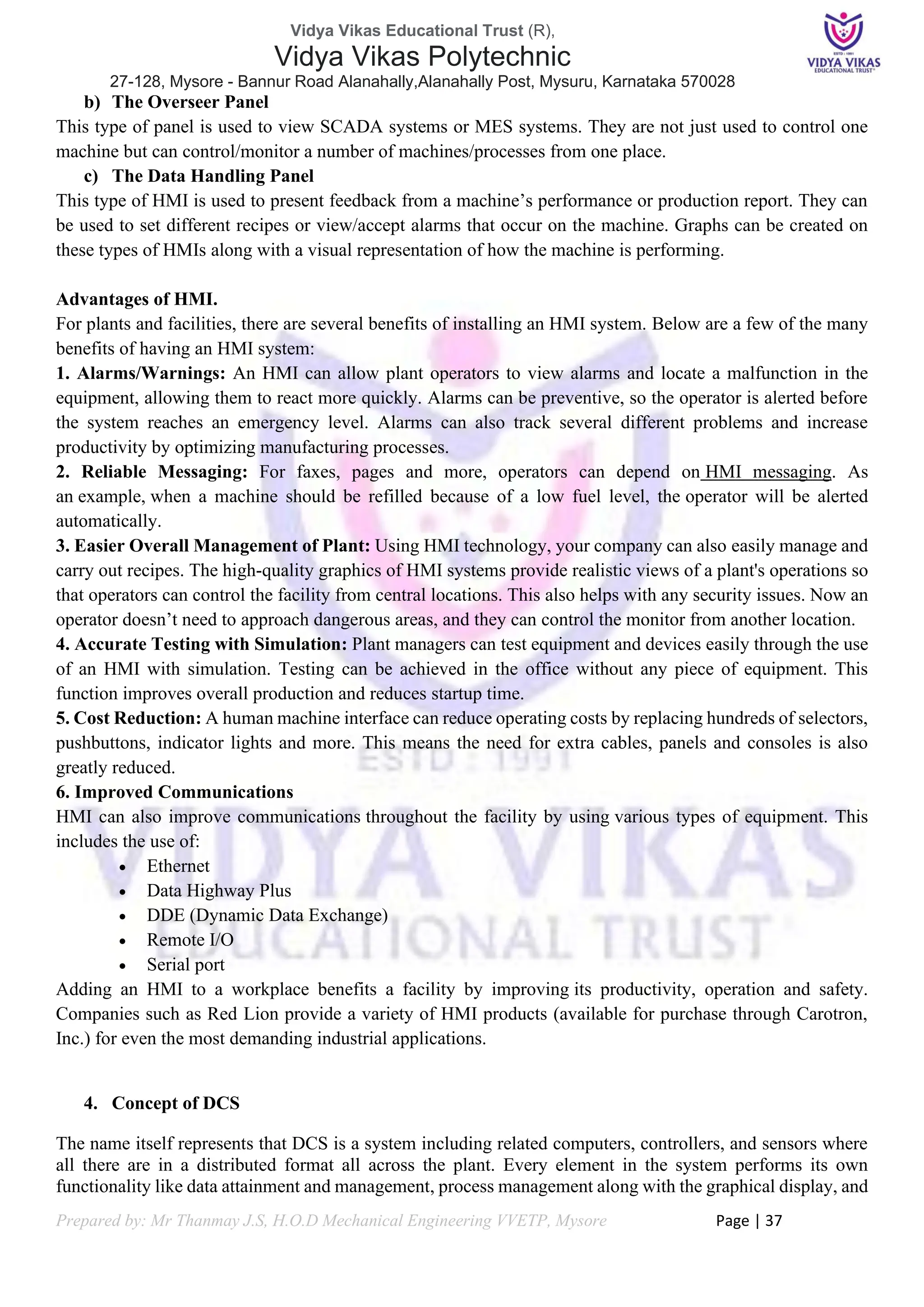
Vidya Vikas Polytechnic
27-128, Mysore - Bannur Road Alanahally,Alanahally Post, Mysuru, Karnataka 570028
Prepared by: Mr Thanmay J.S, H.O.D Mechanical Engineering VVETP, Mysore Page | 2
Course Details
Course Code 20EE43P Semester 04
Course Title
Fundamentals of Automation
Technology
Course Group
Electrical and
Electronics Engineering
No. of Credit 6 Type of Course Program Core
Category PC / Simulation / Output Total contact Hours
8 hours/week
104 hours/semester
Prerequisites Nil Teaching Scheme L: T:P: 3:1:4
CIE Marks 60 SEE Marks 40
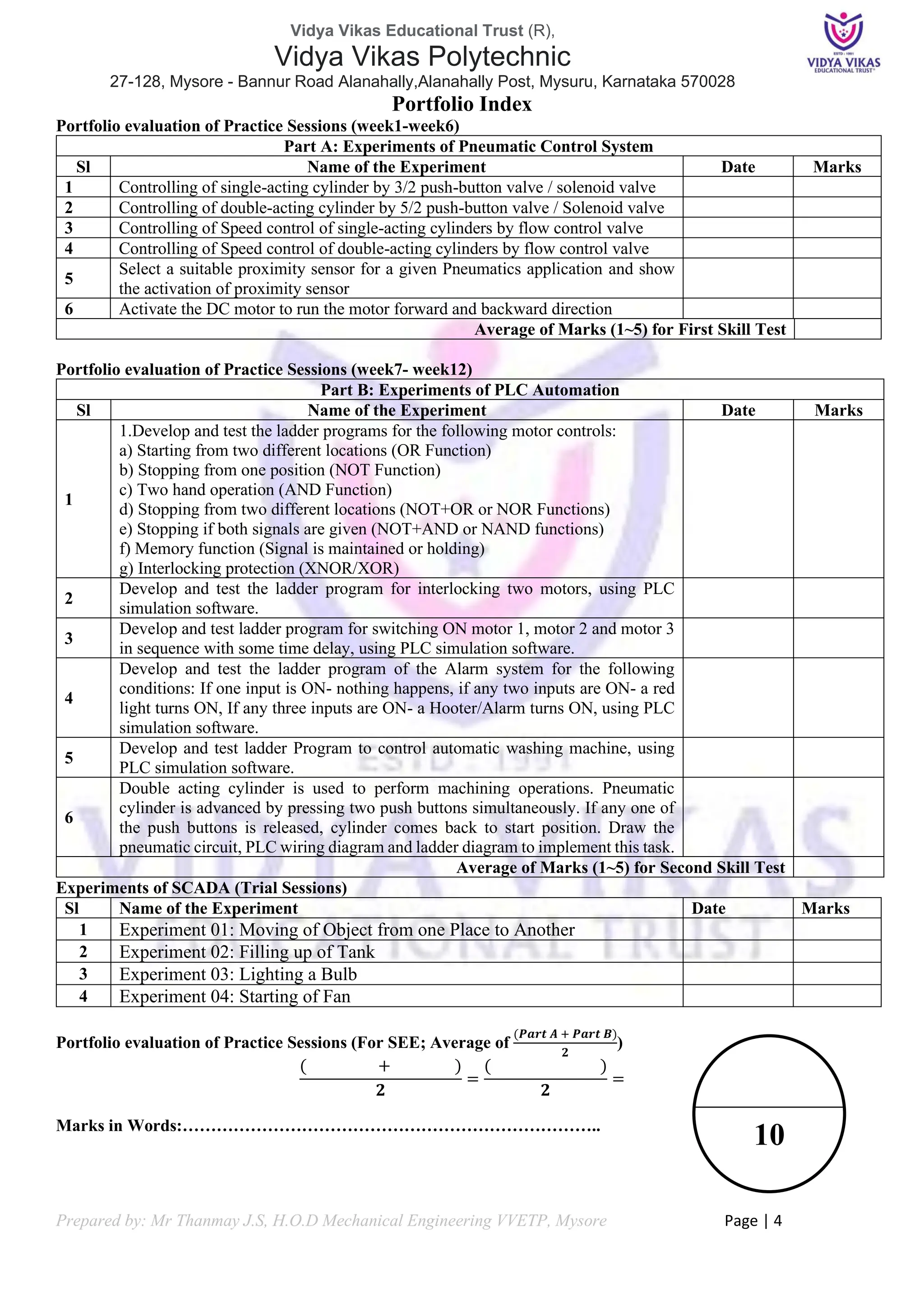
Course Outcome:
CO01 Select a suitable sensor and actuator for a given automation application and demonstrate its use.
CO02 Install, test & control the pneumatic actuators using various pneumatic valves.
CO03 Develop ladder diagrams for a given application and explain its implementation using PLC.
CO04 Describe the concept of SCADA and DCS systems and list their various applications.
Course Assessment:
Sl No Assessments Type Schedule Marks Conversion
1 CIE Assessment 1 Written Test 1 3rd
week 30 Average of 3
Test for 30
Marks
2 CIE Assessment 2 Written Test 2 7th
week 30
3 CIE Assessment 3 Written Test 3 13th
week 30
4 CIE Assessment 4 Skill Test 1 5th
week 100 to 20 Average of 2
Skill Test for
20 Marks
5 CIE Assessment 5 Skill Test 2 9th
week 100 to 20
6 CIE Assessment 6 Portfolio / Record 11th
week 10 10
Total CIE / Internal Marks 60
Semester End Examination (SEE) [Written Exam] 100 40
Total 100
Students Activity Questions:
a) Explain working of circuit
b) List different types of timer relays used in circuit
c) Explain working principle of LVDT and List the applications of LVDT
d) List features of Hall effect sensor and List applications Hall effect sensor
e) List the advantages of pneumatics and explain application of pneumatics in automation
f) Explain terminology from the field of proximity switch technology.
g) List its features and Applications of VFD](https://image.slidesharecdn.com/fundamentalsofautomationtechnology20ee43pportfolio-240520135103-d61f4885/75/Fundamentals-of-Automation-Technology-20EE43P-Portfolio-pdf-2-2048.jpg)


![Vidya Vikas Educational Trust (R),
Vidya Vikas Polytechnic
27-128, Mysore - Bannur Road Alanahally,Alanahally Post, Mysuru, Karnataka 570028
Prepared by: Mr Thanmay J.S, H.O.D Mechanical Engineering VVETP, Mysore Page | 19
Introduction to LogixPro
Layout [Select Micrologix 1000] Input / Output Data [Create Ladder Logic]
Label the I/O Logics Select I/O Simulator
Go online to Run Program or offline mode to
stop
Select RUN Mode to see simulation
Toggle the Input Switches to see Output](https://image.slidesharecdn.com/fundamentalsofautomationtechnology20ee43pportfolio-240520135103-d61f4885/75/Fundamentals-of-Automation-Technology-20EE43P-Portfolio-pdf-19-2048.jpg)


![Vidya Vikas Educational Trust (R),
Vidya Vikas Polytechnic
27-128, Mysore - Bannur Road Alanahally,Alanahally Post, Mysuru, Karnataka 570028
Prepared by: Mr Thanmay J.S, H.O.D Mechanical Engineering VVETP, Mysore Page | 41
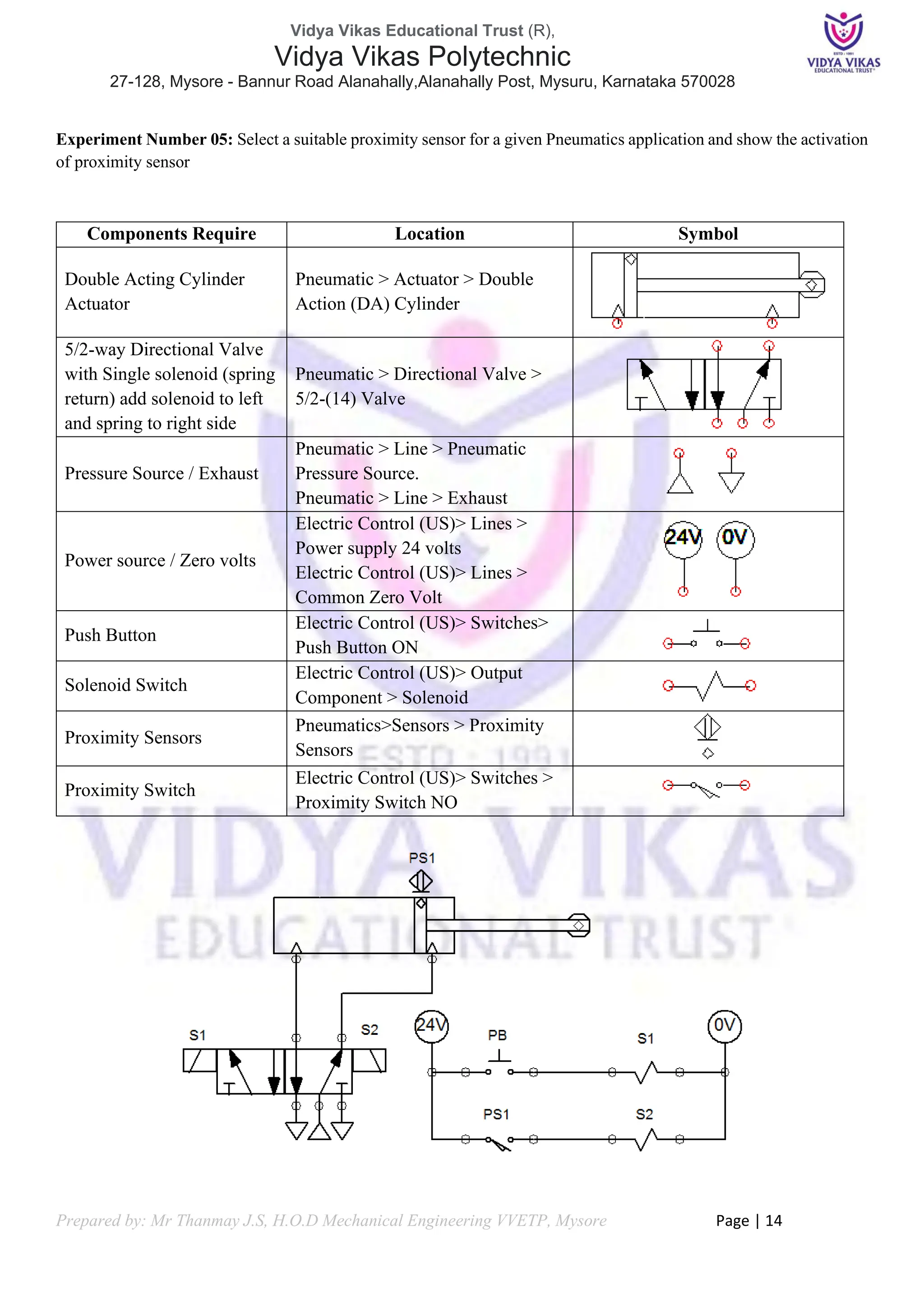
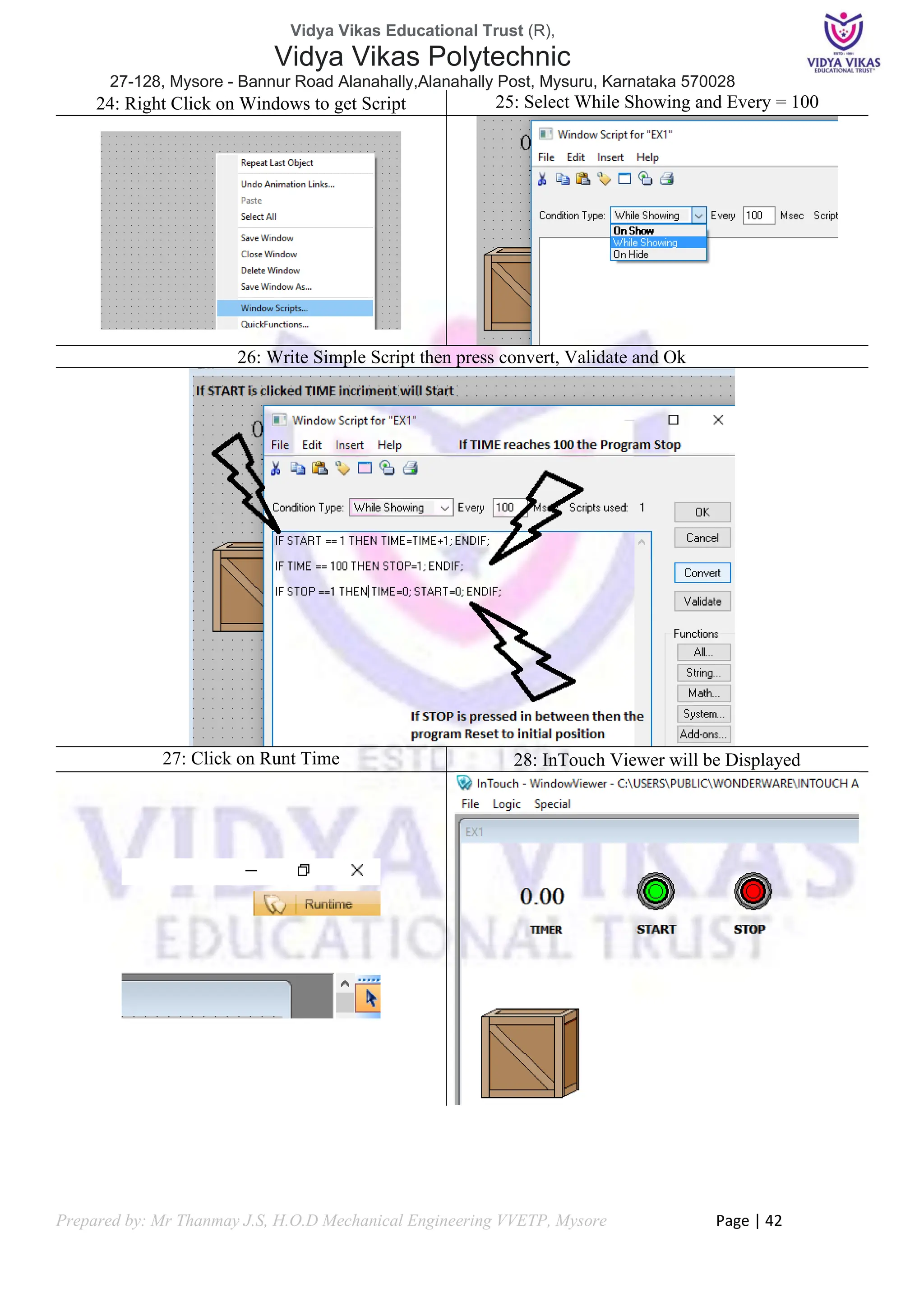
17: Select suitable Symbol for Process [Example
Containers> Crate 1]
18: Select Object and click on Break Cell Icon
below
19: Double Click on Object to get Object Properties
dialog
20: Click on Location > Horizontal (Check box) >
click on Horizontal to get Expression Dialog
21: Enter TIME scale and Moment Distance
22: Define TIME input OK
23: Give TIME input as Memory Real>Save OK>
OK>OK](https://image.slidesharecdn.com/fundamentalsofautomationtechnology20ee43pportfolio-240520135103-d61f4885/75/Fundamentals-of-Automation-Technology-20EE43P-Portfolio-pdf-41-2048.jpg)
![Vidya Vikas Educational Trust (R),
Vidya Vikas Polytechnic
27-128, Mysore - Bannur Road Alanahally,Alanahally Post, Mysuru, Karnataka 570028
Prepared by: Mr Thanmay J.S, H.O.D Mechanical Engineering VVETP, Mysore Page | 45
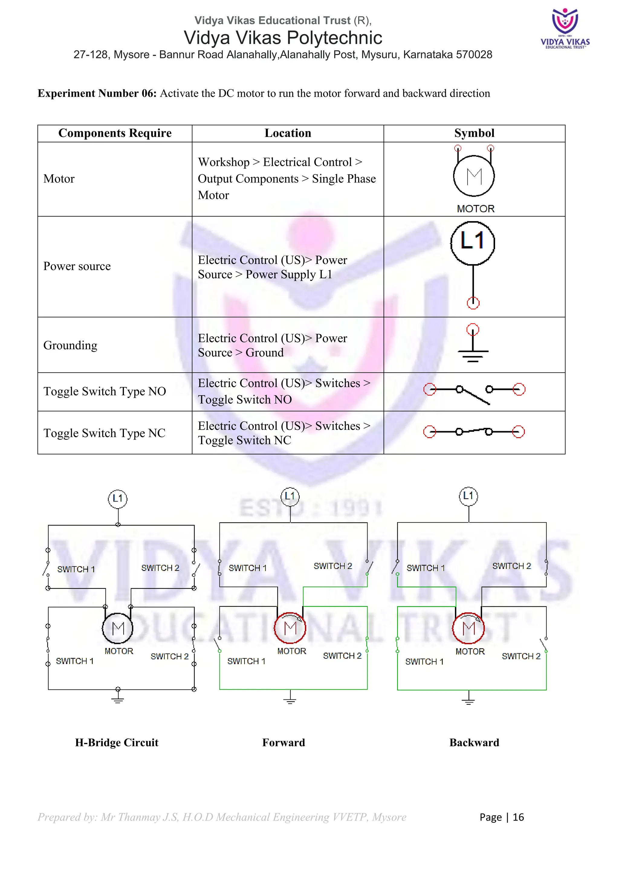
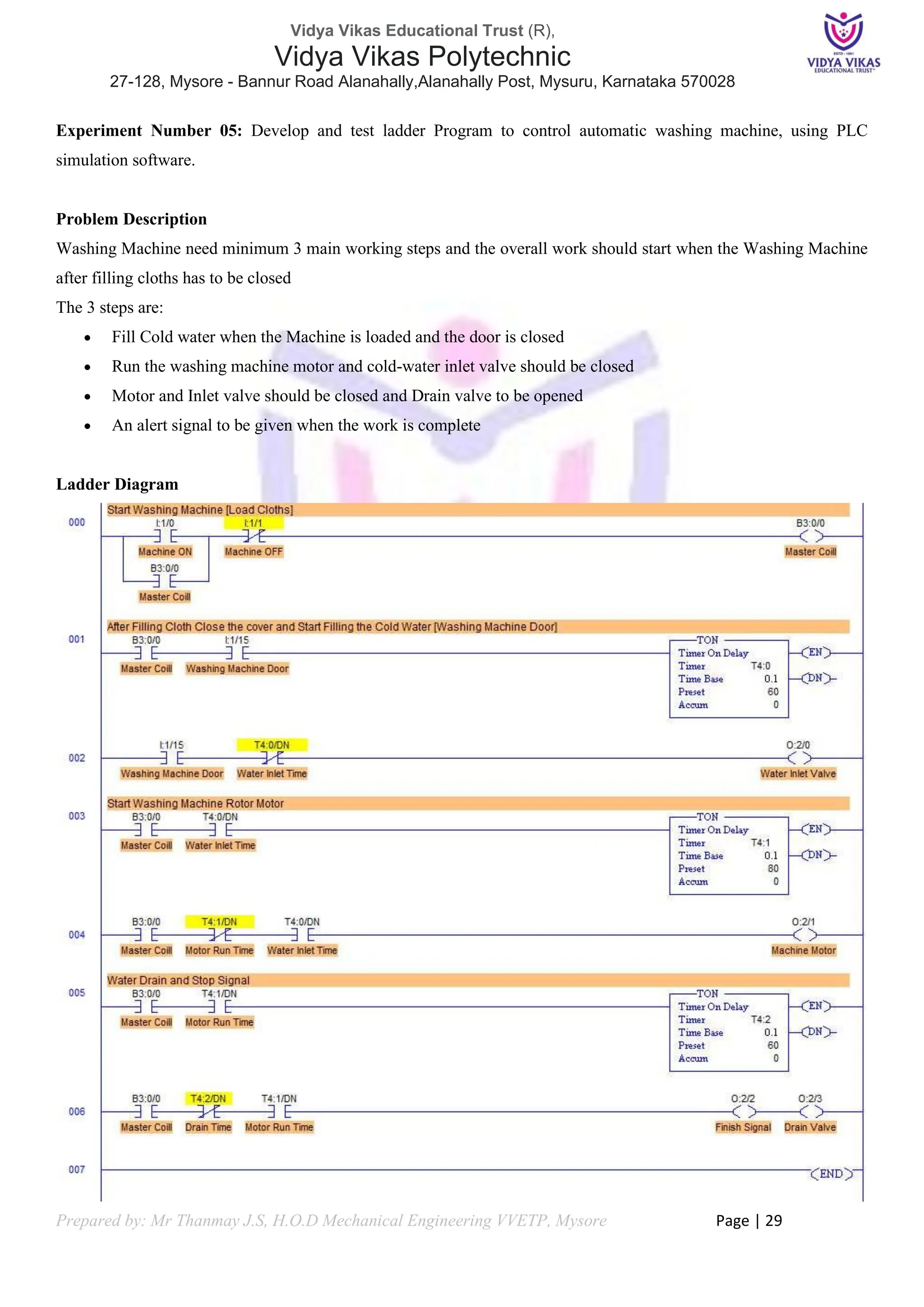
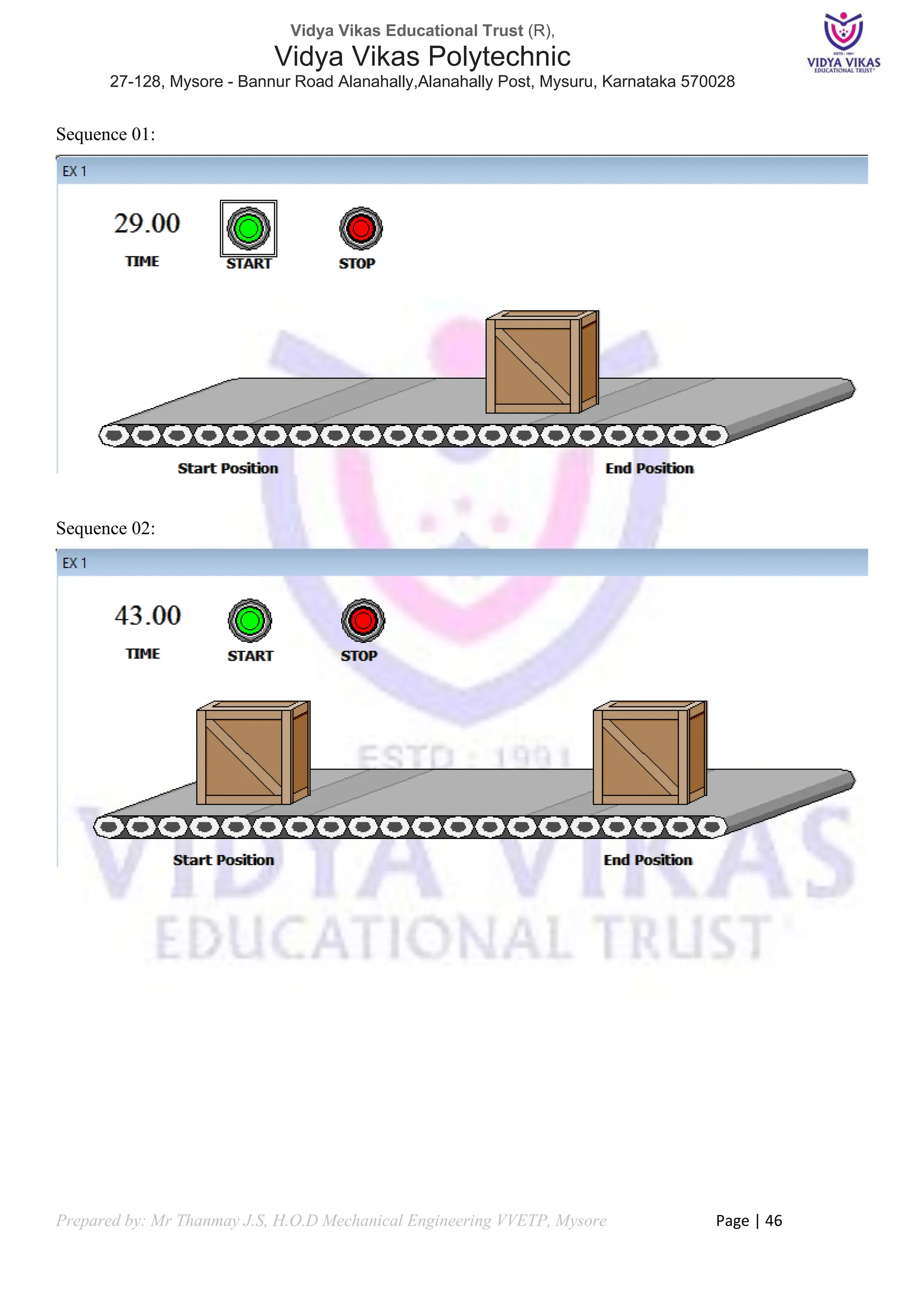
Experiment 01: Moving of Object from one Place to Another
AIM: Program to move objects from conveyor.
Problem Description
❖ Objects are moving on conveyor
❖ We need to move objects on conveyor. When box is reached its position, another box should appear.
❖ Implement this automatic cycle in InTouch SCADA animation.
Problem Solution
❖ Create Time Value Count
❖ Create Buttons to Start and Stop
❖ Create Objects and Elements in InTouch Window
❖ Give Horizontal Movement
❖ Write Initial Conditions to zero in Window Script
❖ Write simple Script to activate
❖ Note the Time for Box to reach Position
❖ Edit Script and Visibility to get second Box
❖ Validate the Results
Components Required
[1] Conveyor Belt
[2] Box or Crater 2 Numbers
[3] Start and Stop Button
[4] Timer
Inputs Initial Conditions
START = 0;
STOP = 0;
TIME = 0;
Onscreen Script
IF START == 1 THEN TIME = TIME+1; ENDIF;
IF TIME == 50 THEN STOP=1; ENDIF;
IF STOP ==1 THEN START=0; TIME = 0; ENDIF;
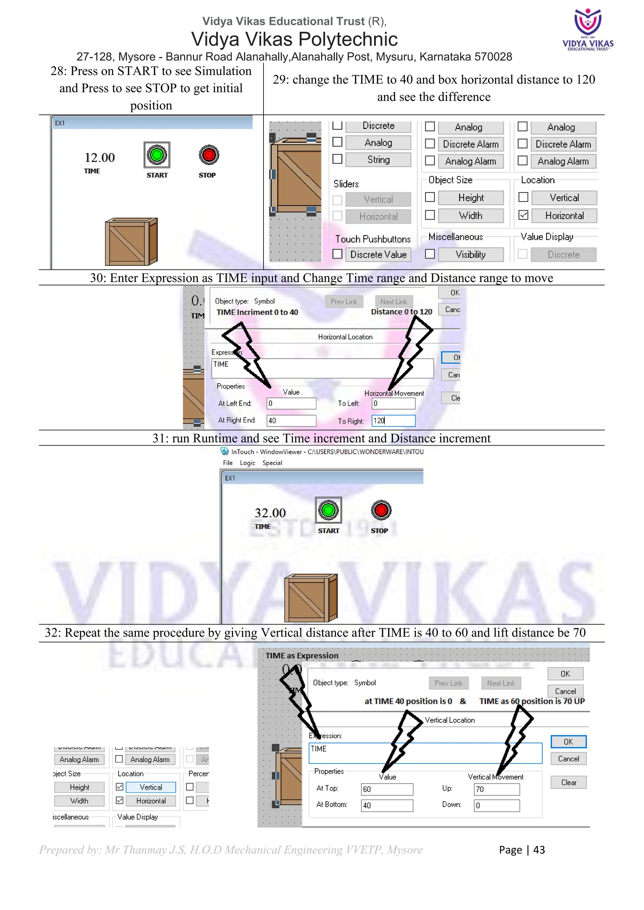
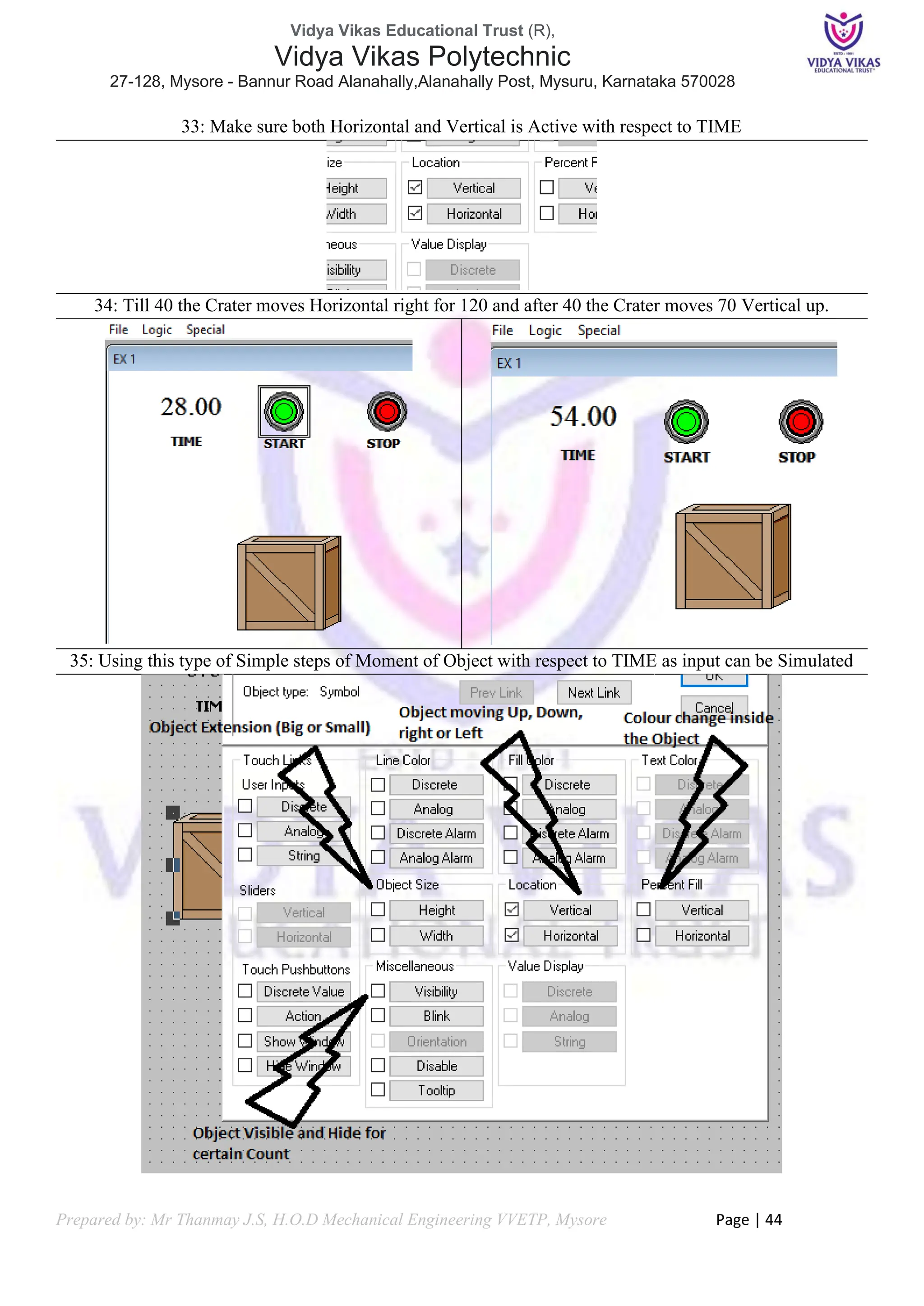
Box parameter
Horizontal: Extension Name TIME; Time Start = 0; Time End = 50; Distance Start = 0; Distance Move =
(Based on Trial); Visibility: Extension = TIME > 40; Visibility on](https://image.slidesharecdn.com/fundamentalsofautomationtechnology20ee43pportfolio-240520135103-d61f4885/75/Fundamentals-of-Automation-Technology-20EE43P-Portfolio-pdf-45-2048.jpg)

![Vidya Vikas Educational Trust (R),
Vidya Vikas Polytechnic
27-128, Mysore - Bannur Road Alanahally,Alanahally Post, Mysuru, Karnataka 570028
Prepared by: Mr Thanmay J.S, H.O.D Mechanical Engineering VVETP, Mysore Page | 48
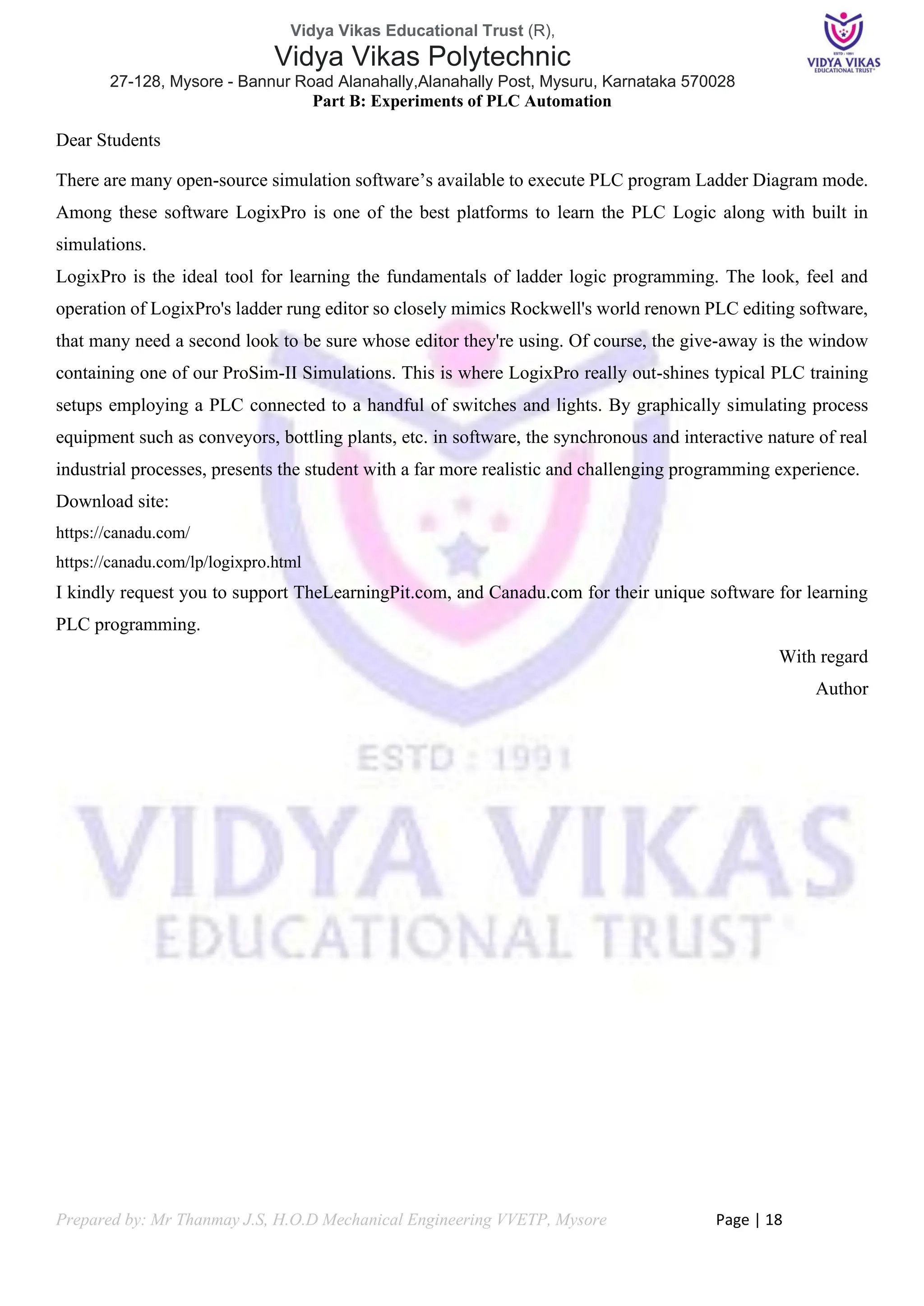
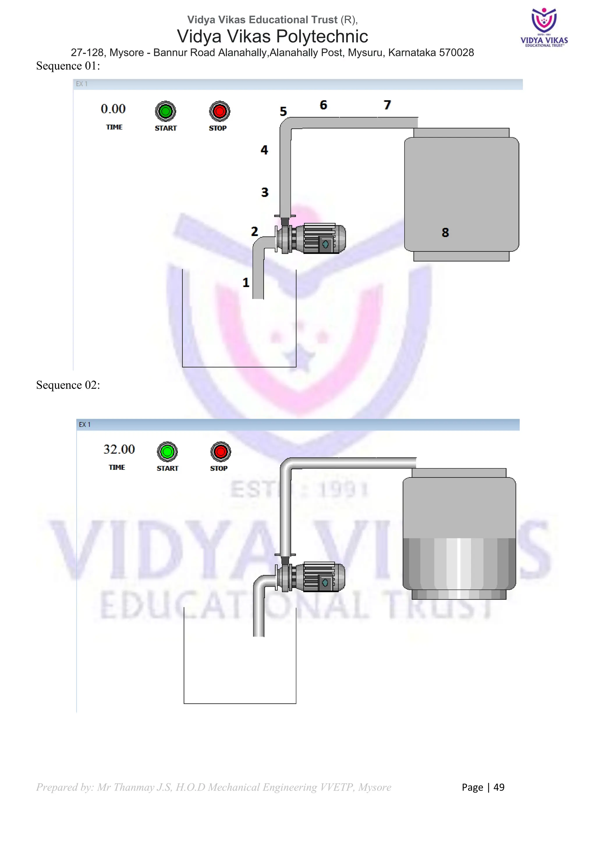
Experiment 02: Filling up of Tank
AIM: From Pump water to be Pumped to Tank
Problem Description
❖ Pump should Display to Pump Water
❖ We need to show Water Moment from Pump to Tank
❖ Implement this automatic cycle in InTouch SCADA animation.
Problem Solution
❖ Create Time Value Count
❖ Create Buttons to Start and Stop
❖ Create Objects and Elements in InTouch Window
❖ Give Vertical and Horizontal Movement for Water
❖ Write Initial Conditions to zero in Window Script
❖ Write simple Script to activate
❖ Note the Time for Tank to Fill and Stop the Sequence
❖ Edit Script and Visibility
❖ Validate the Results
Components Required
[1] Sump
[2] Pump
[3] Pipes
[4] Tank
Inputs Initial Conditions
START = 0;
STOP = 0;
TIME = 0;
Onscreen Script
IF START == 1 THEN TIME = TIME+1; ENDIF;
IF STOP ==1 THEN START=0; TIME = 0; ENDIF;
Water parameter
PIPE TIME HORIZONTAL / VERTICAL
1 0 TO 5 Vertical
2 5 to 10 Horizontal
3 10 to 15 Vertical
4 15 to 20 Vertical
5 20 to 25 Horizontal
6 20 to 25 Horizontal
7 20 to 25 Horizontal
8 25 to 40 Vertical](https://image.slidesharecdn.com/fundamentalsofautomationtechnology20ee43pportfolio-240520135103-d61f4885/75/Fundamentals-of-Automation-Technology-20EE43P-Portfolio-pdf-48-2048.jpg)

![Vidya Vikas Educational Trust (R),
Vidya Vikas Polytechnic
27-128, Mysore - Bannur Road Alanahally,Alanahally Post, Mysuru, Karnataka 570028
Prepared by: Mr Thanmay J.S, H.O.D Mechanical Engineering VVETP, Mysore Page | 51
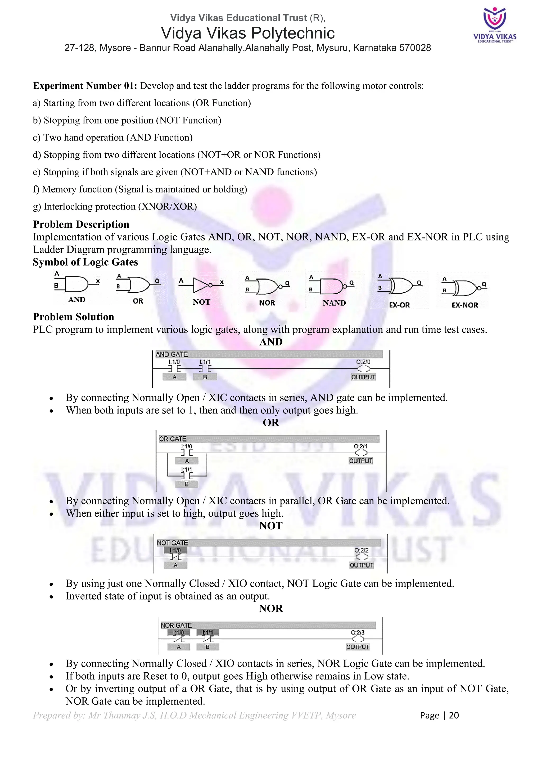
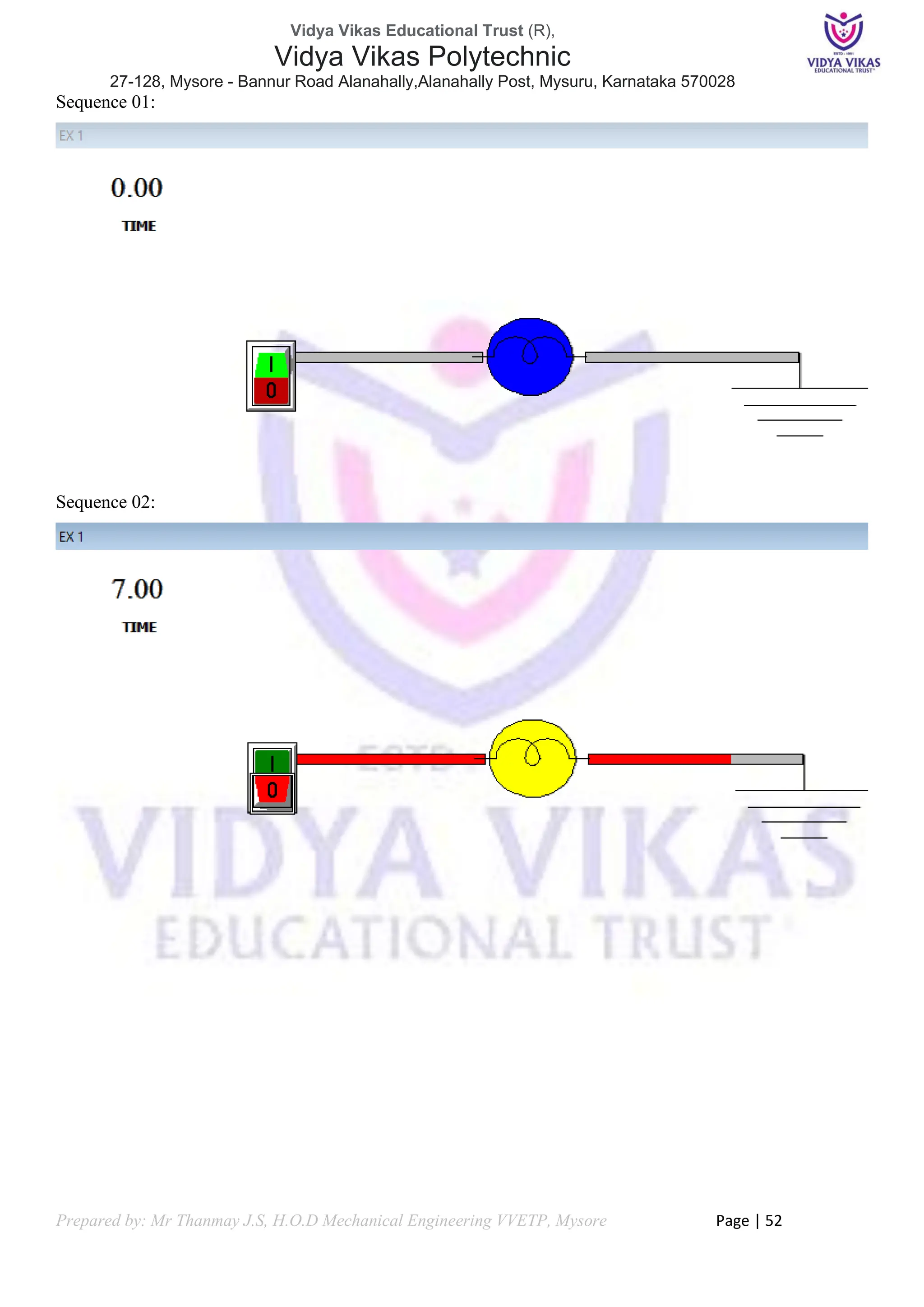
Experiment 03: Lighting a Bulb
AIM: to control a Bulb by Switch
Problem Description
❖ Switch should be a Discreet Memory
❖ Electricity flow by time when switch is ON
❖ Implement this automatic cycle in InTouch SCADA animation.
Problem Solution
❖ Create Time Value Count
❖ Create a Switch
❖ Create wire by small rectangle
❖ Give Horizontal Movement for Electricity
❖ Write Initial Conditions to zero in Window Script
❖ Write simple Script to activate
❖ Note the Time for Electrical Flow and Stop the Sequence
❖ Edit Script and Visibility
❖ Validate the Results
Components Required
[1] Timer
[2] Switch
[3] Bulb
Inputs Initial Conditions
SWITCH = 0;
TIME = 0;
Onscreen Script
IF SWITCH == 1 THEN TIME = TIME+1; ENDIF;
IF SWITCH ==0 THEN TIME = 0; ENDIF;
Current parameter
Horizontal Time Start = 0 End Time =5; Bulb = Blink Continuous after Time 5; Horizontal Time Start = 5
End Time =8 till grounding](https://image.slidesharecdn.com/fundamentalsofautomationtechnology20ee43pportfolio-240520135103-d61f4885/75/Fundamentals-of-Automation-Technology-20EE43P-Portfolio-pdf-51-2048.jpg)

![Vidya Vikas Educational Trust (R),
Vidya Vikas Polytechnic
27-128, Mysore - Bannur Road Alanahally,Alanahally Post, Mysuru, Karnataka 570028
Prepared by: Mr Thanmay J.S, H.O.D Mechanical Engineering VVETP, Mysore Page | 54
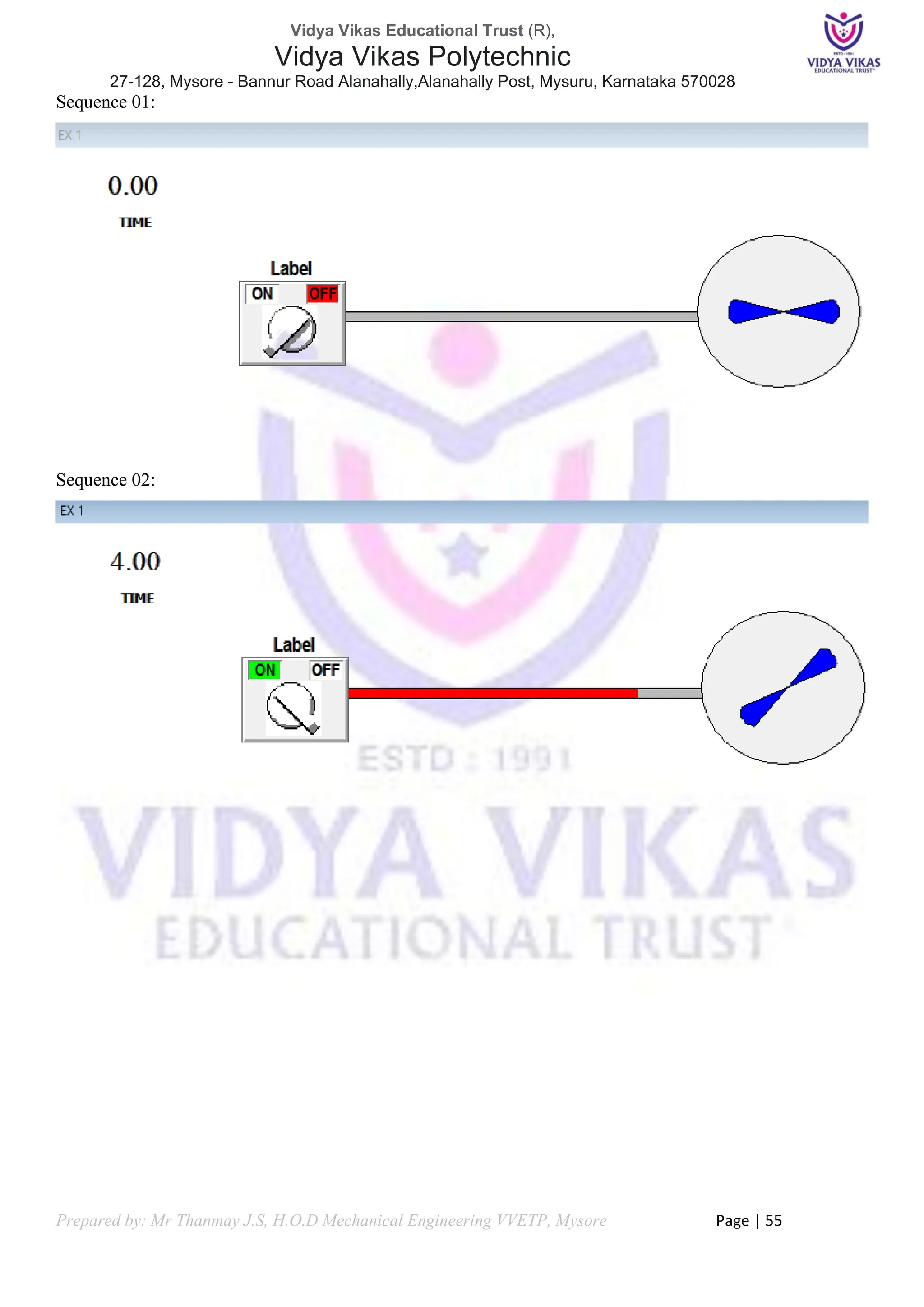
Experiment 04: Starting of Fan
AIM: to control a Fan by Knob
Problem Description
❖ Knob should be a Discreet Memory
❖ Electricity flow by time when Knob is ON
❖ Implement this automatic cycle in InTouch SCADA animation.
Problem Solution
❖ Create Time Value Count
❖ Create a Knob
❖ Create Propellor and Circle
❖ Create wire by small rectangle
❖ Give Horizontal Movement for Electricity
❖ Give Orientation to Propellor
❖ Write Initial Conditions to zero in Window Script
❖ Write simple Script to activate
❖ Note the Time for Electrical Flow and Stop the Sequence
❖ Edit Script and Visibility
❖ Validate the Results
Components Required
[1] Knob
[2] Propellor
[3] Timer
Inputs Initial Conditions
KNOB = 0;
TIME = 0;
Onscreen Script
IF KNOB == 1 THEN TIME = TIME+1; ENDIF;
IF KNOB ==0 THEN TIME = 0; ENDIF;
Current parameter
Horizontal Time Start = 0 End Time =5; Propeller Orientation = Time > 5;](https://image.slidesharecdn.com/fundamentalsofautomationtechnology20ee43pportfolio-240520135103-d61f4885/75/Fundamentals-of-Automation-Technology-20EE43P-Portfolio-pdf-54-2048.jpg)


The document outlines the curriculum for a course titled 'Fundamentals of Automation Technology' at Vidya Vikas Polytechnic, focusing on automation principles, sensor and actuator selection, pneumatic control, and PLC programming. It provides detailed information on course structure, assessment methods, laboratory sessions, and practical experiments, designed for fourth-semester electrical and electronics engineering students. Additionally, it includes certification for lab work and guidance on software usage for automation simulations.


![A_Brief_Summary_on_Summer_Courses[1]](https://cdn.slidesharecdn.com/ss_thumbnails/eba34e5d-9ddb-4049-a6e9-99a5e88c4654-151124202731-lva1-app6892-thumbnail.jpg?width=640&height=640&fit=bounds)


