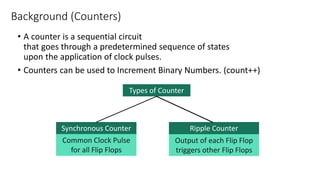
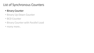
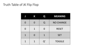
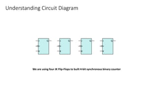
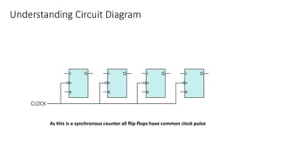
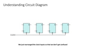
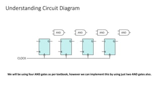
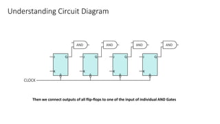
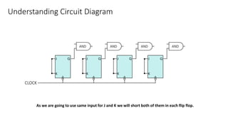
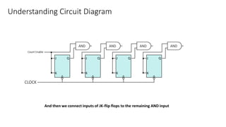
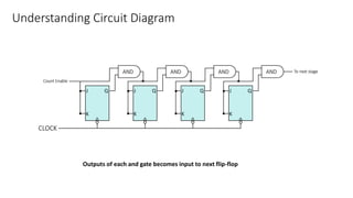
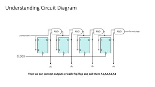
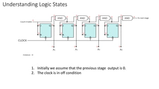
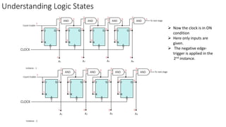
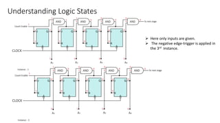
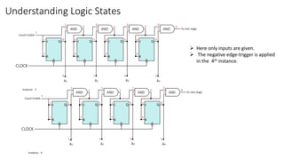
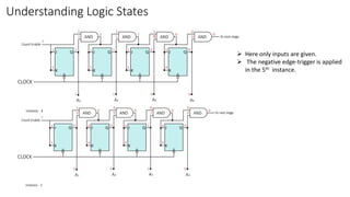
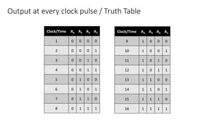
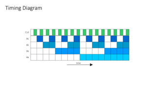
4-bit Synchronous Binary Counter
15CP308, 15CP309, 15CP310, 15CP311
• A counter is a sequential circuit
that goes through a predetermined sequence of states
upon the application of clock pulses.
• Counters can be used to Increment Binary Numbers. (count++)
Background (Counters)
Types of Counter
Synchronous Counter Ripple Counter
Common Clock Pulse
for all Flip Flops
Output of each Flip Flop
triggers other Flip Flops
• Binary Counter
• Binary Up-Down Counter
• BCD Counter
• Binary Counter with Parallel Load
• many more..
List of Synchronous Counters
1. Truth Table of JK Flip Flop
2. Understanding Circuit Diagram
3. Understanding Logic States
4. Output
5. Truth Table
6. Timing Diagram
4-bit Synchronous Binary Counter
Truth Table of JK Flip Flop
J K Q MEANING
0 0 Q NO CHANGE
0 1 0 RESET
1 0 1 SET
1 1 Q’ TOGGLE
Understanding Circuit Diagram
We are using four JK Flip-Flops to built 4-bit synchronous binary counter
Understanding Circuit Diagram
As this is a synchronous counter all flip-flops have common clock pulse
Understanding Circuit Diagram
We just rearranged the clock inputs so that we don’t get confused
Understanding Circuit Diagram
We will be using four AND gates as per textbook, however we can implement this by using just two AND gates also.
Understanding Circuit Diagram
Then we connect outputs of all flip-flops to one of the input of individual AND Gates
Understanding Circuit Diagram
As we are going to use same input for J and K we will short both of them in each flip flop.
Understanding Circuit Diagram
And then we connect inputs of JK-flip flops to the remaining AND input
Understanding Circuit Diagram
Outputs of each and gate becomes input to next flip-flop
Understanding Circuit Diagram
Then we can connect outputs of each flip-flop and call them A1,A2,A3,A4
Understanding Logic States
1. Initially we assume that the previous stage output is 0.
2. The clock is in off condition
Understanding Logic States
 Now the clock is in ON
condition
 Here only inputs are
given.
 The negative edge-
trigger is applied in the
2nd instance.
Understanding Logic States
 Here only inputs are given.
 The negative edge-trigger is applied in
the 3rd instance.
Understanding Logic States
 Here only inputs are given.
 The negative edge-trigger is applied
in the 4th instance.
Understanding Logic States
 Here only inputs are given.
 The negative edge-trigger is applied
in the 5th instance.
Clock/Time A4 A3 A2 A1
1 0 0 0 0
2 0 0 0 1
3 0 0 1 0
4 0 0 1 1
5 0 1 0 0
6 0 1 0 1
7 0 1 1 0
8 0 1 1 1
Output at every clock pulse / Truth Table
Clock/Time A4 A3 A2 A1
9 1 0 0 0
10 1 0 0 1
11 1 0 1 0
12 1 0 1 1
13 1 1 0 0
14 1 1 0 1
15 1 1 1 0
16 1 1 1 1
Timing Diagram

4 bit Binary counter