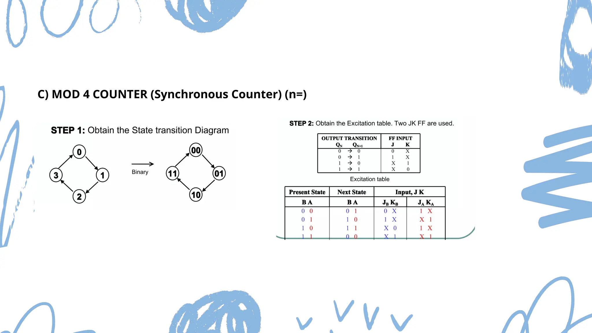
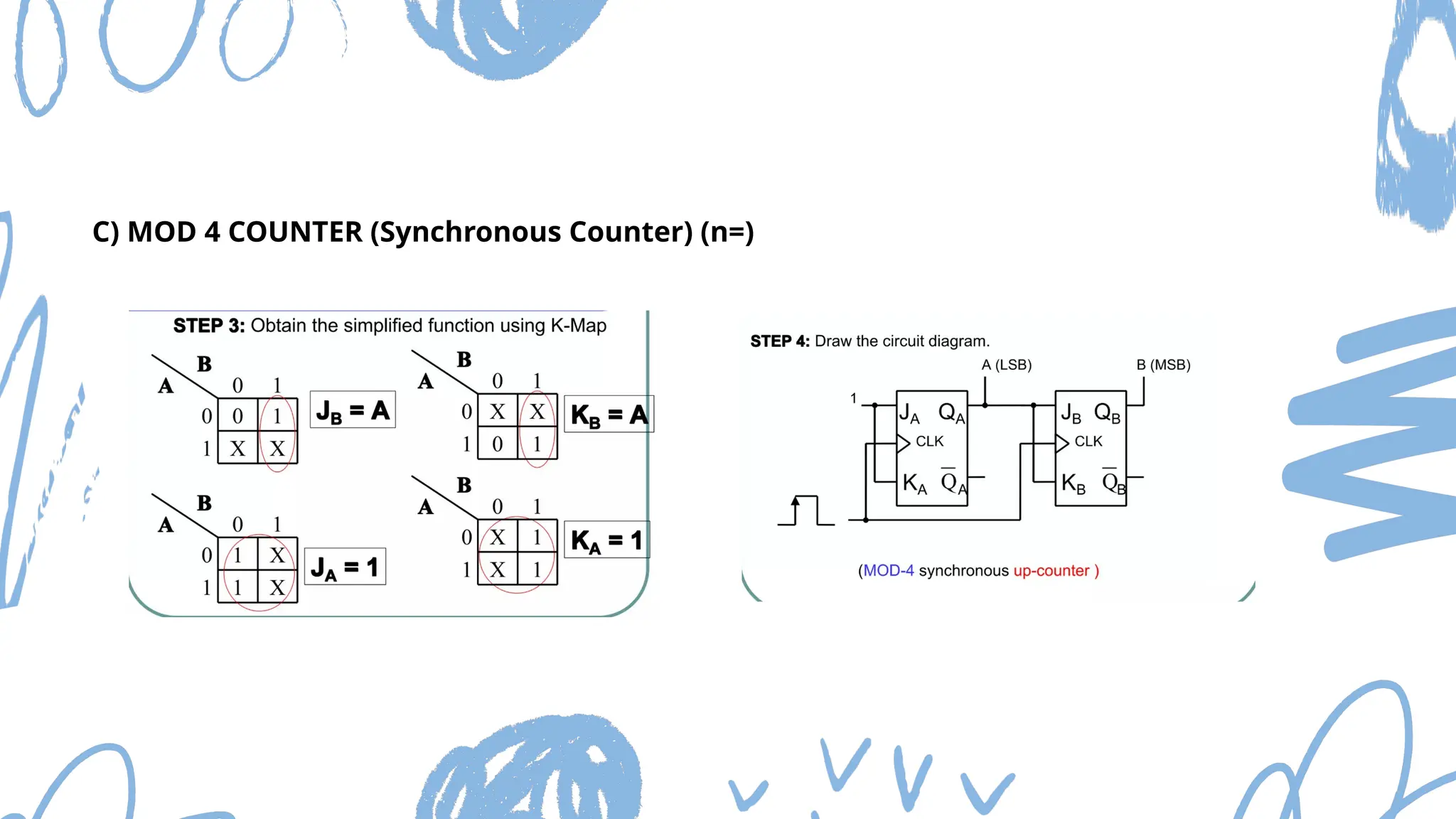
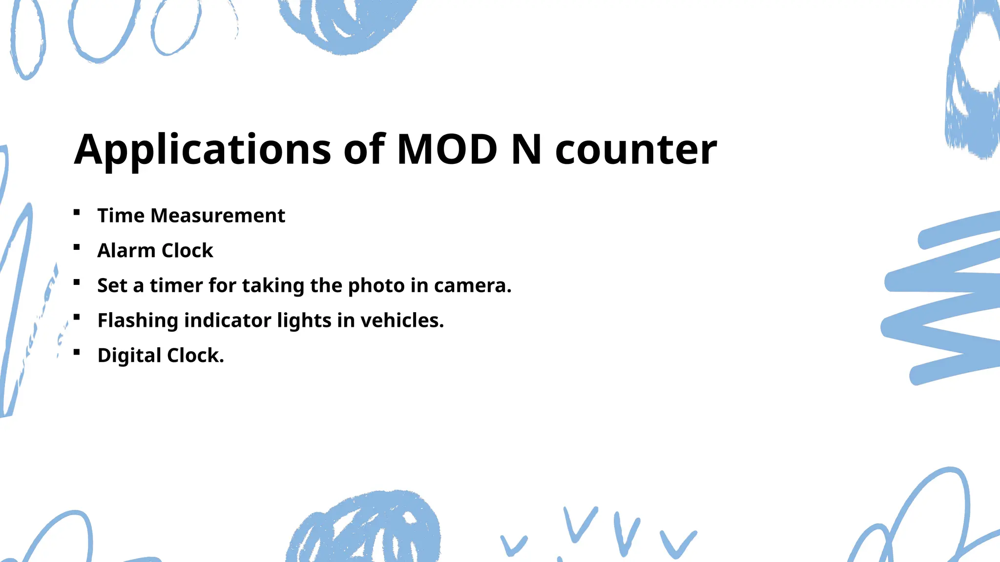
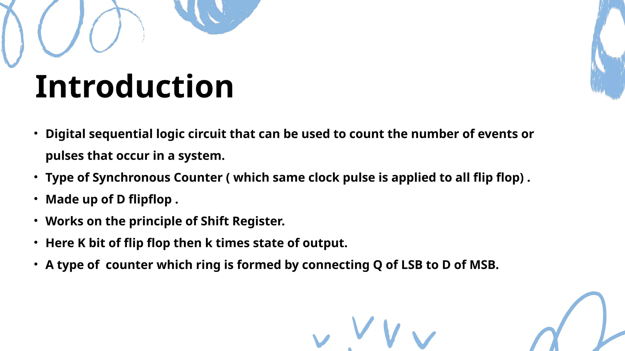
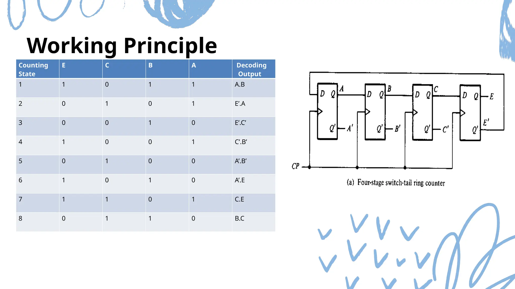
The document discusses Mod n counters, Ring counters, and Johnson counters, detailing their definitions, principles, and applications. Mod n counters utilize flip-flops to count through states, while Ring and Johnson counters are synchronous counters based on shift registers. Various examples and applications for these counters are illustrated, highlighting their importance in digital electronics.


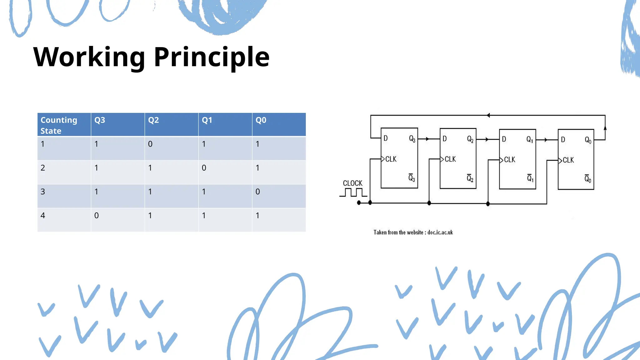


![COUNTERS [Synchronous and Asynchronous]](https://cdn.slidesharecdn.com/ss_thumbnails/counters-211217083059-thumbnail.jpg?width=640&height=640&fit=bounds)


