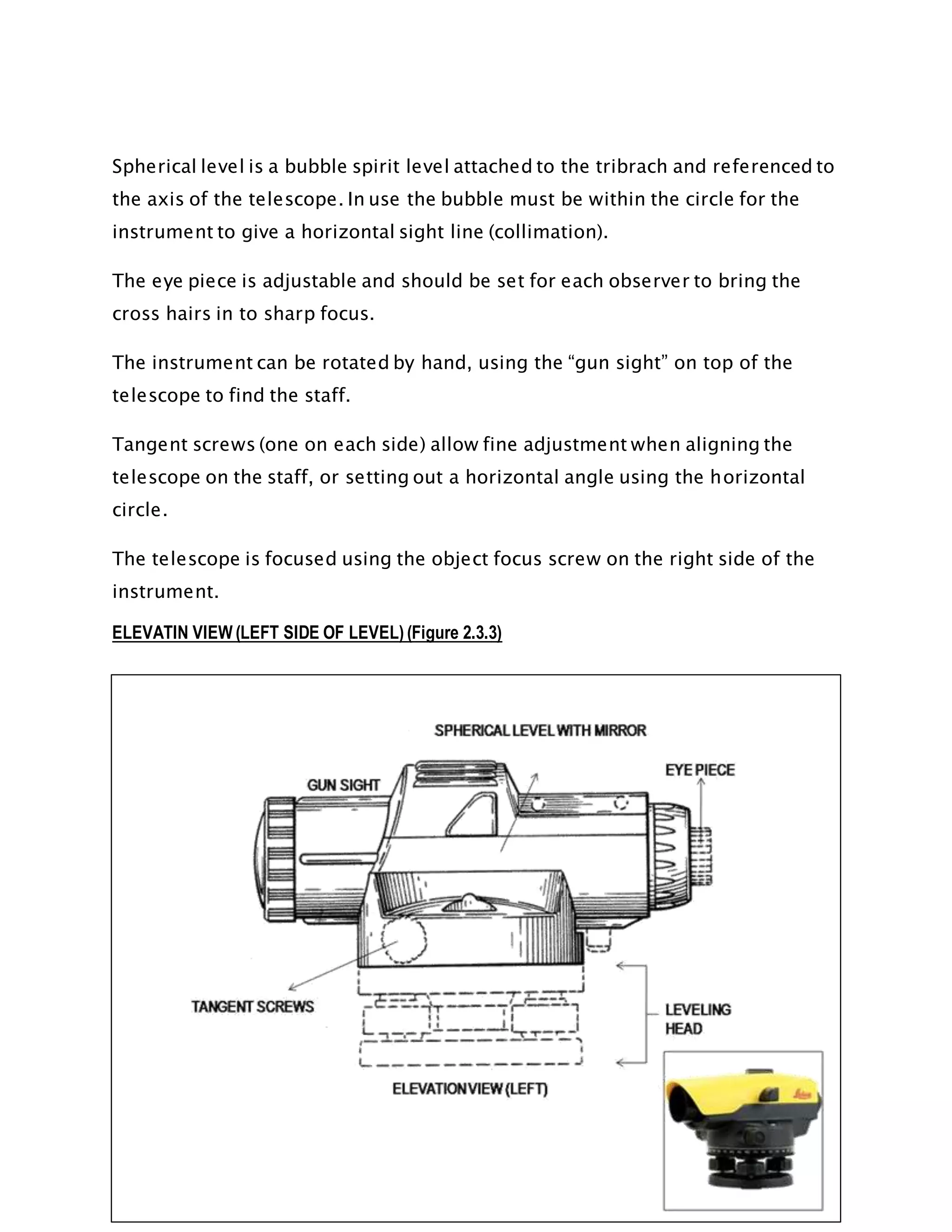
SCHOOL OF ARCHITECTURE, BUILDING AND
DEISGN
BACHELOR OF QUANTITY SURVEYING
(HONOURS)
FIELD WORK REPORT 1
LEVELLLING
SITE SURVEYING ( QSB 60103 )
LECTURER : MR. CHAI VOON CHIET
DATE OF SUBMISSION :
GROUP MEMBERS : GOH XINGXIN 0325587
CHEAH MAN YEE 0324743
DAPHNE TAN LI WEN 0329055
FARAH AIDA 0322962
CONTENT
OBJECTIVES PG 1
1.0 INTRODUCTIONTO LEVELING PG 2 – PG 8
1.1 DEFINITIONS OF TERMS USED IN LEVELING
1.2 LEVELING METHOD
1.3 ARITHMETICAL CHECK
1.4 DIFFERENTIAL LEVELING
2.0 OUTLINEOF APPARATUS PG 9 – PG 20
2.1 AUTOMATIC LEVEL
2.2 TRIPOD STAND
2.3 LEVELING ROD
2.4 OPTICAL PLUMMET
2.5 THREE-SCREW LEVELING
2.6 CIRCULAR SPIRIT BUBBLE
3.0 LEVELINGFIELDWORK PG 21 – PG
24
3.1 FIELDWORK DATA
3.2 ADJUSTED DATA
4.0 DISCUSSION AND RECOMMENDATIONS PG 25
5.0 CONCLUSION PG 25
1.0 INTRODUCTIONTOLEVELING
Leveling is the art of determining the relative heights or elevations of the
different points are objects on the earth’s surface in the area under survey. It
deals with measurements in a vertical plan. Surveyor uses an instrument for
observing levels, having a sighting device, usually telescopic, and capable of
being made precisely horizontal. Leveling result can used for design in
highways, railways, sewers and more. Besides that, it can also use to calculate
of earthwork and develop maps showing general ground configurations. It can
use as a site layout for new facilities such as roads, structural foundations,
contouring drainage as well as estimating the fall of pipe.
1.1 DEFINITIONS OF TERMS USED IN LEVELING
Level Surface
A surface parallel to the mean spheroid of the earth is called a level surface and
the line drawn on the level surface is known as a level line. Hence all points
lying on a level surface are equidistant from the center of the earth.
Datum
Datum is any surface to which elevation are referred. The mean sea level
affords a convenient datum world over, and elevations are commonly given as
so much above or below sea level. It is often more convenient, however, to
assume some other datum, especially, if only the relative elevation of points are
required.
Elevation
The elevation of a point on or near the surface of the earth is its vertical
distance above or below an arbitrarily assumed level surface or datum. The
difference in elevation between two points its vertical distance between the two
level surfaces in which the two point lie.
Bench Mark (B.M)
A benchmark (B.M.) is a definite point on a permanent object which has a
known elevation and a known location. Temporary benchmarks, (T.B.M.) are
used many times to supplement permanent benchmarks. The elevation and
location of these points are also known but not intended to be permanent. A
benchmark is a point of reference which is convenient for leveling in a given
locality.
Reduced level (RL)
A reduce level is the height or elevation above the point adopted as the site
datum for the purpose of establishing levels. To establish the required depths
for a drainage system you need to work from the datum point.
Mean sea level (MSL)
The most commonly used reference surface for vertical distance is mean sea
level.
Running levels (or Leveling)
Running level is a process the surveyor to determine the elevations of points.
Back sight (BS)
Back sight is the first staff reading taken by the surveyor after the levelling
instrument is set up and levelled. B.S is generally taken on the point of known
reduced level as on the benchmark or a change point
An Intermediate sight (I. S.):
It is any other staff reading taken on appoint of unknown elevation from the
same set up of the level. All sights taken between the back sight and the fore
sight and the foresight are intermediate sights.
Fore sight (FS)
Foresight is the last staff reading taken before changing the instrument to the
other position. It is the staff reading taken on point whose RL is to determined.
This sight is considered as negative and deduced from Height of Instrument to
determine RL of the point.
A change point (C. P):
It is appoint denoting the shifting of the level. It is a point on which is the fore
and back sights are taken. Any stable and well defined object such as a
boundary stone, curb stone rail, rock etc. is used as a change point. A bench
mark may also be taken as a changer point. It is also called a turning point (T.
P).
The line of collimation:
It is the line joining the intersection of cross hairs of the optical center of the
object glass. It is also called the line of sight.
The height of instrument (H. L):
It is the elevation (or the R.L.) of the plane of collimation (or plane of sight)
when the instrument is correctly leveled. It is also called the height of plane of
the collimation.
To determine elevation of points two instruments are required, viz.
1. A level
2. A leveling staff or rod.
1.2 LEVELINGMETHOD
A. Height of Collimation Method
It consist of finding the elevation of the plane of collimation ( H.I.) for every set
up of the instrument, and then obtaining the reduced level of point with
reference to the respective plane of collimation.
B. Rise and fall method
It consists of determining the difference of elevation between consecutive
points by comparing each point after the first that immediately preceding it.
The difference between there staff reading indicates a rise fall according to the
staff reading at the point. The R.L is then found adding the rise to, or
subtracting the fall from the reduced level of preceding point.
1.2.1DIFFERENCESBETWEEN HEIGHT OF COLLIMATIONAND RISE AND FALL
METHOD
No. Height of Collimation Method Rise and Fall Method
1 It is rapid as it involves few It is laborious involving several
1.3 ARITHMETICAL CHECK
An arithmetical check should be applied either at the end of the operation or at
the end of each page when entries are carried forward over several pages.
A. Height of Collimation method
The sum of each collimation height multiplied by the number of reduced levels
obtained from it is equal to the sum of all the intermediate sights, foresights,
and reduced levels excluding the first reduced level.
B. Rise and Fall method
calculation calculation
2
There is no check on the RL of the
intermediate sight
There is a check on the RL of the
intermediate points
3
Errors in the intermediate RL
cannot be detected
Errors in the intermediate RLs can
be detected as all the points are
correlated
4
There are two checks on the
accuracy of RL calculation
There are three checks on the
accuracy of RL calculation
5
This method is suitable for
longitudinal levelling where there
are a number of intermediate
sights
This method is suitable for fly
levelling where there are no
intermediate sights
∑(BS) – ∑(FS) = Last RL – First RL
The sum of the back-sights minus the sum of the foresights is equal to the sum
of the rises minus the sum of the falls, and is also equal to the first reduced
level minus the last reduced level.
1.4 DIFFERENTIAL LEVELING
Differential levelling is the process of measuring vertical distances from a
known elevation point to determine elevations of unknown points. The most
common methods to determine elevation are through the use of a compensator
type, automatic (engineering level) and level rod(s), and an electronic digital
barcode levelling instrument with barcode rod. By far the most common
levelling method, and the one most surveyors are concerned with. It comprises
a telescopic sight and a sensitive spirit bubble vial. A thorough knowledge of
levelling principles and proper application of methods and equipment will
prevent costly delays and generate the needed results and accuracy.
A single-level setup is illustrated in Figure. A back sight reading is taken on a
rod held on a point of known elevation. That elevation is transferred vertically
to the line of sight by reading the rod and then adding the known elevation and
the back sight reading. The elevation of the line of sight is the height of
instrument (HI). By definition, the line of sight is horizontal; therefore, the line
of sight elevation can then be transferred down to the unknown elevation point
by turning the telescope to the foresight and reading the rod. The elevation of
the foresight station is found by subtracting the rod reading from the height of
instrument. Note that the difference in elevation from the back sight station to
the foresight station is determined by subtracting the foresight rod reading
from the back sight rod reading.
OBJECTIVES
 To ensure students understand the methods that are used during leveling.
 Providing proper understanding of leveling principle, theory and application.
 To allow students to conduct the fieldwork to familiarize themselves to the
reality of working on a site.
 Allowing students to experience how to work the apparatus by themselves.
For instance, setting up the tripod stand and adjusting the bubble.
 Teach students to be responsible and take extra care when handling the
apparatus.
 To allow students to determine the error that occurred during recording data
and applying formulae.
 To teach students on how to differentiate between what is backsight,
intersight and foresight.
 Teach students how to cooperate in a teamwork.
2.0 OUTLINEOF APPARATUS
The level, its tripod, the staff and the staff bubble are all precision items of
equipment upon which the accuracy of the work is highly dependent. They shall
be kept correctly calibrated, and be used and stored with care. Levels shall be
carried in vehicles in a padded box, case or shelf in addition to the normal case,
and staves shall be kept in a canvas or plastic sleeve to prevent damage to the
face and entry of dirt. A level is basically a telescope attached to an accurate
leveling device, set upon a tripod so that it can rotate horizontally through 360°.
Normally the leveling device is a bubble, but modern ones incorporate a
pendulum. Also, level is the instrument used to furnish horizontal line of sight
for observing staff readings and determining R.L.s. There are three basic types
of level, such as Automatic level, Digital level, Dumpy level and also Tilting level.
However, we are using the automatic level to conduct this field work. The basic
components of level are shown below (Figure 2.0.1):
Figure 2.0.1 Basic Components of automatic level
Sources: http://www.levelling.uhi.ac.uk/tutorial1_4.html
2.1 AUTOMATICLEVEL
Automatic level, have become a much more common optical instrument on
construction sites because they are easier to use and quicker to set up. Builders,
contractors and other professionals will normally have an automatic level
(professional leveling tool) to assist them in the setting of site levels. Automatic
level also can be termed as self- aligning level. It is a recent development. The
fundamental difference between automatic and the classic spirit level is that in
the former the line of sight is no longer leveled manually using a tubular spirit
level, but is leveled automatically within a certain tilt range. This is achieved by
compensator in the telescope. It has a compensator which consists of an
arrangement of three prisms. The two outer ones are attached to the barrel of
the telescope. The middle prism is suspended by fine wiring and reacts to
gravity. The instrument is secured to the tripod head using the tripod screw.
Other than that, before we use the automatic level, we must set up and make
sure the spirit bubble is in the center of the black circle.
ELEVATION VIEW (RIGHT SIDE OF LEVEL) (Figure 2.1.1)
Figure 2.1.1 Elevation View (Right Side of Level)
Source: https://www.google.com/patents/USD440506
The leveling head has three parts which includes a top plate or tribrach which
carries a spirit level and the instrument. Three leveling, or foot, screws and a
foot plate or trivet that attaches to the tripod head.
The horizontal circle is to allow the instrument to be used to measure
horizontal angles to an accuracy of 1°.
The object focusing screw is used to bring the staff or image in to focus.
TOP VIEW (TOP OF LEVEL) (Figure 2.2.2)
Figure 2.2.2 Top View (Top of Level)
Source: https://www.google.com/patents/USD440506
Spherical level is a bubble spirit level attached to the tribrach and referenced to
the axis of the telescope. In use the bubble must be within the circle for the
instrument to give a horizontal sight line (collimation).
The eye piece is adjustable and should be set for each observer to bring the
cross hairs in to sharp focus.
The instrument can be rotated by hand, using the “gun sight” on top of the
telescope to find the staff.
Tangent screws (one on each side) allow fine adjustment when aligning the
telescope on the staff, or setting out a horizontal angle using the horizontal
circle.
The telescope is focused using the object focus screw on the right side of the
instrument.
ELEVATIN VIEW (LEFT SIDE OF LEVEL) (Figure 2.3.3)
Figure 2.3.3 Elevation View (Left Side of Level)
Source: https://www.google.com/patents/USD440506
The only new component in this view is the mirror over the spherical level. This
mirror allows the observer to see the bubble and confirm that the instrument is
correctly leveled before taking a reading. Not all instruments will have a mirror.
2.2 TRIPOD STAND
A tripod is a three-legged stand, important in providing the foundation for
automatic level and other leveling instruments such as rotary laser levels, line
laser levels, dot laser levels, builder’s levels and even sometimes torpedo laser
levels. Tripods are portable and provide support and stability along both the
side-to-side and up-and-down axis motion. There are two different kinds of
tripods such as adjustable-leg tripods and fixed tripods. For conducting this
fieldwork, we are using adjustable-leg tripods. Adjustable-Leg tripods are the
more common
of the two in the
construction world,
especially outdoors
because of generally
uneven terrain.
The
adjustable- leg tripod
is easier to set up on uneven ground because each leg can be adjusted to
exactly the height needed to find level, even on a very steep slope. The
adjustable-leg tripod is also easy to transport due to having retractable legs.
TRIPOD COMPONENTS
(Figure 2.2.1)
A tripod is made up of three legs, each with metal points called shoes; and a
head
which the automatic level or other leveling device attached.
Figure 2.2.1 Tripod Components
Source: http://www.johnsonlevel.com/News/WhatisaTripodHowdoTripods
HEAD
The head of the tripod is attached to the legs and allows a steady surface to
connect leveling devices. The tool you are using will dictate the type of tripod
head needed. For most automatic level applications, a dome head (Figure 2.2.1)
is used. There are three different kinds of heads which includes flat head, dome
head and threaded base.
POINTS
Each tripod, whether fixed or adjustable, has metal points (Figure 2.2.1) on the
end of the legs for added stability and can help provide a stable environment
for the leveling tools on top of the tripod. When working outdoors, points on
the bottom of the tripod are essential, but when working indoors, metal points
can slide or scratch floors. Some tripods can be purchased with rubber
attachments which prevents either of these from happening.
LEGS
The most common materials for tripod legs are steel, aluminum, fiberglass and
wood. Among all the materials the most durable and yet heaviest is steel;
however, the lightweight and sturdy is aluminum. Wood and fiberglass legs
are the most accurate materials used in making tripod legs because of their
lack of sensitivity to changes in temperature.
2.3 LEVELINGROD
A Grade Rod or leveling rods, is a graduated rod used to determine differences
in elevation. Leveling rods can be used with surveyor, optical and laser levels.
Leveling rods can be made up of several different materials; however, the most
common are made out of wood, plastic and fiberglass. Besides, leveling rods
also use different graduations. They can be graduated many different ways
including feet with inches, fractions, tenths with
hundredths and meters with centimeters. The
most common engineer's rod is called the
Philadelphia Rod (Figure 2.3.1). The Philly rod has a
front side as well as a back side. Along with all
other Grade Rods, it is important to ensure that the Philly rod is fully extended;
if it is only extended partially, the graduations will not be accurate. Each foot on
the Philly rod is divided into hundredths of a foot. The distance between the
hundredths is painted black on a white background. The bottom of the black
mark is odd values, and the top of the black mark is even values. The rod must
be placed on the correct point exactly and held plumb throughout. If the rod is
in the wrong place or not held plumb, the readings will be incorrect and useless.
In keeping the rod plumb, a bulls-eye level may be used. If there is not a bulls-
eye level attached to the rod, you can make sure its plumb by lining it up with
the vertical crosshair of the telescope on the instrument being used.
Figure 2.3.1 Philadelphia Rod
Source: http://www.johnsonlevel.com/News/GradeRodsAllAboutGradeRod
Figure 2.3.2 Leveling Rod Reading
Source: http://free-ed.net/free-ed/Resources/Trades/carpentry/Building01/default.asp?iNum=0402
2.4 OPTICAL PLUMMET
Optical plummet also can know as tribrach (Figure 2.4.1). Optical instrument
are used for surveying purposes and are supported on, and attached to, the
upper end of a tripod by means of a tribrach device. The tribrach used a simple
screw fixing to the tripod plate; it’s relatively easy to replace and the plate can
be modified to fit other mountings such as scaffold tube, railway lines and
more. It’s small and light and makes cheap tripods work harder. A good
tribrach will get precise results from a poor tripod but not the other way around.
Tribrachs are equipped with a bull’s eye bubble for leveling and optical
plummets for setting up precisely on a survey mark.
The ability to “leapfrog” back sight, instrument point and foresight by using
interchangeable tribraches increases the speed, efficiency and accuracy of the
traverse survey. Whenever possible, the tribrach should be detached from the
instruments and placed on the tripods for either theodolite or EDM setups.
This procedure speeds up the setting up process and protects the instrument
from accidents. In some cases, the same tribrach can be used to perform
angular or distance
measurement, as well as GPS
observations from the same survey
point.
Figure 2.4.1 Optical plummet or Tribrach
Source: https://billboyheritagesurvey.wordpress.com/2010/06/29/tribrach/
2.5 THREE-
SCREW
LEVELING
A typical three-screw leveling head is shown in Figure 2.5.1. When the
instrument is placed on its base, the hold-down screw is passed upward
through a hole in the base and threaded in the flat spring that holds the ends of
the leveling screws down on the footplate. Each screw can be used
independently. This gives a very smooth action and makes the leveling
procedure very simple; moreover, as no stress can be transferred to the bearing,
the bearing cannot be deformed by the leveling screws.
When anyone of the leveling screws is turned, the height of the line of sight is
changed. Inadvertent use of the leveling screws after the first sight has been
taken will thus cause errors in using the instrument. It should be noted that
three-screw leveling heads can be used with level instruments only on tilting
levels and on automatic levels. All levels must be leveled just before taking each
sight. Only the tilting levels and the automatic levels are arranged so that this
can be accomplished without using the leveling screws and thus changing the
height of the line of sight.
Figure 2.5.1 Three Screw Leveling
Source: https://www.hofstragroup.com/article/how-use-three-screw-leveling-head-transits-theodolites-levels/
HOW TO USE THREE SCREWS LEVELING
To use the three-screw leveling head. To level an instrument with a three-screw
leveling head, the following procedure should be followed. To center the bubble
in a circular vial, turn that leveling screw clockwise whose direction from the
center of the instrument is the same as the direction in which the bubble
should move. In Figure 2.5.2 the left diagram shows the effect of turning a
screw clockwise, and the right diagram shows the effect of turning a screw
counterclockwise. The bubble can always be centered by using only two screws.
Figure 2.5.2 How to Use Three-Screw Leveling
Source: https://www.hofstragroup.com/article/how-use-three-screw-leveling-head-transits-theodolites-levels/
2.6 CIRCULAR SPIRIT BUBBLE
Instrument is leveled into a horizontal position by means of spirit bubble. Spirit
bubble is in a transparent container filled with a low viscosity liquid, e.g.
alcohol or ether. The precision of bubble depends on the radius of curvature.
In generallarger radius will enable better precision. If the precision is too high,
bubble becomes too sensitive to any move, and it can be very time consuming
to establish horizontal position and high precision might be sometimes
unpractical.
For self-leveling and digital instruments, circular bubble is built-in. Circular
container is of lower precision than tubular vial, but lower precision is
compensated by other internal optical components of the instrument.
Tripod legs have to be laid solidly, and once the instrument is leveled, we have
to avoid further touching (until the instrument is being taken to a next setup).
We use carefully instrument's telescopic sight (optic) only for reading values.
Figure 2.6.1 Circular Spirit Bubble
Source: http://surveying.structural-analyser.com/chapter05/
Figure 2.6.2 Circular Spirit Bubble
Source: http://www.pavingexpert.com/setout04.html
3.0 LEVELINGFIELDWORK
The picture above shows the map for the field work that had been conducted in
Taylors Lakeside’s University.
3.1 FIELDWORKDATA
3.1.0 HEIGHT OF COLLIMATION
3.1.1 RISE AND FALL
Back sight Intermediate Fore sight Rise Fall
Reduced
Level
Remarks
1.360 100.000 BM 1
1.316 3.615 2.255 97.745 TP 1
1.269 1.271 0.045 97.790 TP 2
1.326 1.343 0.074 97.716 TP 3
1.380 1.381 0.055 97.661 TP 4
1.214 1.096 0.284 97.945 TP 5
1.213 1.273 0.059 97.886 TP 6
1.333 1.452 0.239 97.647 TP 7
1.109 1.197 0.136 97.783 TP 8
3.550 1.209 0.100 97.683 TP 9
1.343 1.299 2.251 99.934 TP 10
1.310 0.033 99.967 BM 1
Back sight Intermediate Fore sight Collimation
Reduced
Level
Remarks
1.360 101.360 100.000 BM 1
1.316 3.615 99.061 97.745 TP 1
1.269 1.271 99.059 97.790 TP 2
1.326 1.343 99.042 97.716 TP 3
1.380 1.381 99.041 97.661 TP 4
1.214 1.096 99.158 97.945 TP 5
1.213 1.273 99.099 97.886 TP 6
1.333 1.452 98.980 97.647 TP 7
1.109 1.197 98.892 97.783 TP 8
3.550 1.209 101.233 97.683 TP 9
1.343 1.299 101.277 99.934 TP 10
1.310 99.967 BM 1
3.2 ADJUSTEDDATA
3.2.0 HEIGHT OF COLLIMATIONMETHOD
Back sight Intermediate Fore sight Collimation
Reduced
Level
Correction
Adjusted
RL
Remarks
1.360 101.360 100.000 100.000 BM 1
1.316 3.615 99.061 97.745 +0.003 97.748 TP 1
1.269 1.271 99.059 97.790 +0.006 97.796 TP 2
1.326 1.343 99.042 97.716 +0.009 97.725 TP 3
1.380 1.381 99.041 97.661 +0.012 97.673 TP 4
1.214 1.096 99.158 97.945 +0.015 97.960 TP 5
1.213 1.273 99.099 97.886 +0.018 97.904 TP 6
1.333 1.452 98.980 97.647 +0.021 97.668 TP 7
1.109 1.197 98.892 97.783 +0.024 97.807 TP 8
3.550 1.209 101.233 97.683 +0.027 97.710 TP 9
1.343 1.299 101.277 99.934 +0.030 99.964 TP 10
1.310 99.967 +0.033 100.000 BM 1
16.413 16.446 99.967
-16.446 -100.000
-0.033 -0.033 Arith.
checked
Misclosure = 0.033m
= 33mm
Acceptable misclosure = 12√k , where k is the number of set up
= 12√11
= 39.79mm
Hence, the accuracy of this work is acceptable
Error Distributions= 0.033 ÷ 11
= 0.003
Hence, correction per set up is 0.003m and is cumulative as shown in the table
above
3.2.1 RISE AND FALL METHOD
Back
sight
Inter-
mediate
Fore
sight
Rise Fall
Reduced
Level
Correction
Adjusted
RL
Remarks
1.360 100.000 100.000 BM 1
1.316 3.615 2.255 97.745 +0.003 97.748 TP 1
1.269 1.271 0.045 97.790 +0.006 97.796 TP 2
1.326 1.343 0.074 97.716 +0.009 97.725 TP 3
1.380 1.381 0.055 97.661 +0.012 97.673 TP 4
1.214 1.096 0.284 97.945 +0.015 97.960 TP 5
1.213 1.273 0.059 97.886 +0.018 97.904 TP 6
1.333 1.452 0.239 97.647 +0.021 97.668 TP 7
1.109 1.197 0.136 97.783 +0.024 97.807 TP 8
3.550 1.209 0.100 97.683 +0.027 97.710 TP 9
1.343 1.299 2.251 99.934 +0.030 99.964 TP 10
1.310 0.033 99.967 +0.033 100.000 BM 1
16.413 16.446 2.749 2.782 100.000
- 16.413 -2.749 -99.967
0.033 0.033 0.033 Arith.
checked
Misclosure = 0.033m
= 33mm
Acceptable misclosure = 12√k , where k is the number of set up
= 12√11
= 39.79mm
Hence, the accuracy of this work is acceptable
Error Distributions= 0.033 ÷ 11
= 0.003
Hence, correction per set up is 0.003m and is cumulative as shown in the table
above
4.0 DISCUSSION AND RECOMMENDATIONS
There are a few factors that we have learned that could have affected the
leveling work and there are also steps that could have been avoid and taken to
get a more accurate reading. The recommendations are:
1. Magnetic sources would affect the reading; therefore put mobile phone
and electronic devices away.
2. Ensure the bubbles are properly level.
3. Make sure to triple check the reading that has been taken.
5.0 CONCLUSION
We had learnt the procedure of leveling and the calculation through the
assignment. Initially, we are given a field to measure which located at Taylor’s
carpark. We had a map to refer on and the given reduced level of Bench Mark 1
(BM 1) is 100.00 m. The leveling process begins with obtaining the back sight
(BS) of BM1 and the foresight (FS) of turning point 1 (TP 1). Then we shifted the
auto level to obtain the back sight (BS) of turning point (TP 1) and the foresight
(FS) of turning point 2 (TP 2). This process is repeated by shifting the auto level
to obtain the back sight (BS) and foresight (FS) of the following staff stations.
After that we went back to Bench Mark 1 (BM 1) in order to obtain its FS in order
to calculate the error of misclosure. After completed the leveling at the field
work, we decided to use both height of collimation and rise and fall method to
calculate the reduced level of each staff station. Our error of collected data
misclosure is 33mm. According to the third order of accuracy, the maximum
allowable error of closure is ±39.79mm by using the formulae of ±12√k,
where k represents the number of set-ups. Thus, our leveling result is
acceptable. Hence, the reduced level is able to be equivalent to the benchmark
given which is 100.00 m by distributing the error to each set-up. As a future
Quantity Surveyor, it is essential for us to learn some of the knowledge of site
surveying which is inter-related to the construction process. Surveying is the
technique, profession, and science of determining the dimensions and contour
of the Earth's surface. Using specialized surveying equipment such as automatic
level, leveling rod, and tripod and so on, professional surveyors determine land
boundaries for a variety of important reasons. One of the most common
reasons for a consumer to acquire the assistance of a surveyor is the
acquisition of a new piece of land, as it has to be legally determined where one
person's property ends and another begins for government issued deeds.
Additionally, surveyors work with cartographers to create accurate maps.

SITE SURVEYING LEVELING

  • 1.
    SCHOOL OF ARCHITECTURE,BUILDING AND DEISGN BACHELOR OF QUANTITY SURVEYING (HONOURS) FIELD WORK REPORT 1 LEVELLLING SITE SURVEYING ( QSB 60103 ) LECTURER : MR. CHAI VOON CHIET DATE OF SUBMISSION : GROUP MEMBERS : GOH XINGXIN 0325587 CHEAH MAN YEE 0324743
  • 2.
    DAPHNE TAN LIWEN 0329055 FARAH AIDA 0322962 CONTENT OBJECTIVES PG 1 1.0 INTRODUCTIONTO LEVELING PG 2 – PG 8 1.1 DEFINITIONS OF TERMS USED IN LEVELING 1.2 LEVELING METHOD 1.3 ARITHMETICAL CHECK 1.4 DIFFERENTIAL LEVELING 2.0 OUTLINEOF APPARATUS PG 9 – PG 20 2.1 AUTOMATIC LEVEL 2.2 TRIPOD STAND 2.3 LEVELING ROD 2.4 OPTICAL PLUMMET 2.5 THREE-SCREW LEVELING 2.6 CIRCULAR SPIRIT BUBBLE 3.0 LEVELINGFIELDWORK PG 21 – PG 24 3.1 FIELDWORK DATA 3.2 ADJUSTED DATA 4.0 DISCUSSION AND RECOMMENDATIONS PG 25
  • 3.
    5.0 CONCLUSION PG25 1.0 INTRODUCTIONTOLEVELING Leveling is the art of determining the relative heights or elevations of the different points are objects on the earth’s surface in the area under survey. It deals with measurements in a vertical plan. Surveyor uses an instrument for observing levels, having a sighting device, usually telescopic, and capable of being made precisely horizontal. Leveling result can used for design in highways, railways, sewers and more. Besides that, it can also use to calculate
  • 4.
    of earthwork anddevelop maps showing general ground configurations. It can use as a site layout for new facilities such as roads, structural foundations, contouring drainage as well as estimating the fall of pipe. 1.1 DEFINITIONS OF TERMS USED IN LEVELING Level Surface A surface parallel to the mean spheroid of the earth is called a level surface and the line drawn on the level surface is known as a level line. Hence all points lying on a level surface are equidistant from the center of the earth. Datum Datum is any surface to which elevation are referred. The mean sea level affords a convenient datum world over, and elevations are commonly given as so much above or below sea level. It is often more convenient, however, to assume some other datum, especially, if only the relative elevation of points are required.
  • 5.
    Elevation The elevation ofa point on or near the surface of the earth is its vertical distance above or below an arbitrarily assumed level surface or datum. The difference in elevation between two points its vertical distance between the two level surfaces in which the two point lie. Bench Mark (B.M) A benchmark (B.M.) is a definite point on a permanent object which has a known elevation and a known location. Temporary benchmarks, (T.B.M.) are used many times to supplement permanent benchmarks. The elevation and location of these points are also known but not intended to be permanent. A benchmark is a point of reference which is convenient for leveling in a given locality. Reduced level (RL) A reduce level is the height or elevation above the point adopted as the site datum for the purpose of establishing levels. To establish the required depths for a drainage system you need to work from the datum point. Mean sea level (MSL) The most commonly used reference surface for vertical distance is mean sea level. Running levels (or Leveling) Running level is a process the surveyor to determine the elevations of points.
  • 6.
    Back sight (BS) Backsight is the first staff reading taken by the surveyor after the levelling instrument is set up and levelled. B.S is generally taken on the point of known reduced level as on the benchmark or a change point An Intermediate sight (I. S.): It is any other staff reading taken on appoint of unknown elevation from the same set up of the level. All sights taken between the back sight and the fore sight and the foresight are intermediate sights. Fore sight (FS) Foresight is the last staff reading taken before changing the instrument to the other position. It is the staff reading taken on point whose RL is to determined. This sight is considered as negative and deduced from Height of Instrument to determine RL of the point.
  • 7.
    A change point(C. P): It is appoint denoting the shifting of the level. It is a point on which is the fore and back sights are taken. Any stable and well defined object such as a boundary stone, curb stone rail, rock etc. is used as a change point. A bench mark may also be taken as a changer point. It is also called a turning point (T. P).
  • 8.
    The line ofcollimation: It is the line joining the intersection of cross hairs of the optical center of the object glass. It is also called the line of sight. The height of instrument (H. L): It is the elevation (or the R.L.) of the plane of collimation (or plane of sight) when the instrument is correctly leveled. It is also called the height of plane of the collimation. To determine elevation of points two instruments are required, viz. 1. A level 2. A leveling staff or rod. 1.2 LEVELINGMETHOD A. Height of Collimation Method It consist of finding the elevation of the plane of collimation ( H.I.) for every set up of the instrument, and then obtaining the reduced level of point with reference to the respective plane of collimation.
  • 9.
    B. Rise andfall method It consists of determining the difference of elevation between consecutive points by comparing each point after the first that immediately preceding it. The difference between there staff reading indicates a rise fall according to the staff reading at the point. The R.L is then found adding the rise to, or subtracting the fall from the reduced level of preceding point. 1.2.1DIFFERENCESBETWEEN HEIGHT OF COLLIMATIONAND RISE AND FALL METHOD No. Height of Collimation Method Rise and Fall Method 1 It is rapid as it involves few It is laborious involving several
  • 10.
    1.3 ARITHMETICAL CHECK Anarithmetical check should be applied either at the end of the operation or at the end of each page when entries are carried forward over several pages. A. Height of Collimation method The sum of each collimation height multiplied by the number of reduced levels obtained from it is equal to the sum of all the intermediate sights, foresights, and reduced levels excluding the first reduced level. B. Rise and Fall method calculation calculation 2 There is no check on the RL of the intermediate sight There is a check on the RL of the intermediate points 3 Errors in the intermediate RL cannot be detected Errors in the intermediate RLs can be detected as all the points are correlated 4 There are two checks on the accuracy of RL calculation There are three checks on the accuracy of RL calculation 5 This method is suitable for longitudinal levelling where there are a number of intermediate sights This method is suitable for fly levelling where there are no intermediate sights ∑(BS) – ∑(FS) = Last RL – First RL
  • 11.
    The sum ofthe back-sights minus the sum of the foresights is equal to the sum of the rises minus the sum of the falls, and is also equal to the first reduced level minus the last reduced level. 1.4 DIFFERENTIAL LEVELING Differential levelling is the process of measuring vertical distances from a known elevation point to determine elevations of unknown points. The most common methods to determine elevation are through the use of a compensator type, automatic (engineering level) and level rod(s), and an electronic digital barcode levelling instrument with barcode rod. By far the most common levelling method, and the one most surveyors are concerned with. It comprises a telescopic sight and a sensitive spirit bubble vial. A thorough knowledge of levelling principles and proper application of methods and equipment will prevent costly delays and generate the needed results and accuracy.
  • 12.
    A single-level setupis illustrated in Figure. A back sight reading is taken on a rod held on a point of known elevation. That elevation is transferred vertically to the line of sight by reading the rod and then adding the known elevation and the back sight reading. The elevation of the line of sight is the height of instrument (HI). By definition, the line of sight is horizontal; therefore, the line of sight elevation can then be transferred down to the unknown elevation point by turning the telescope to the foresight and reading the rod. The elevation of the foresight station is found by subtracting the rod reading from the height of instrument. Note that the difference in elevation from the back sight station to the foresight station is determined by subtracting the foresight rod reading from the back sight rod reading. OBJECTIVES  To ensure students understand the methods that are used during leveling.  Providing proper understanding of leveling principle, theory and application.  To allow students to conduct the fieldwork to familiarize themselves to the reality of working on a site.  Allowing students to experience how to work the apparatus by themselves. For instance, setting up the tripod stand and adjusting the bubble.  Teach students to be responsible and take extra care when handling the apparatus.
  • 13.
     To allowstudents to determine the error that occurred during recording data and applying formulae.  To teach students on how to differentiate between what is backsight, intersight and foresight.  Teach students how to cooperate in a teamwork.
  • 14.
    2.0 OUTLINEOF APPARATUS Thelevel, its tripod, the staff and the staff bubble are all precision items of equipment upon which the accuracy of the work is highly dependent. They shall be kept correctly calibrated, and be used and stored with care. Levels shall be carried in vehicles in a padded box, case or shelf in addition to the normal case, and staves shall be kept in a canvas or plastic sleeve to prevent damage to the face and entry of dirt. A level is basically a telescope attached to an accurate leveling device, set upon a tripod so that it can rotate horizontally through 360°. Normally the leveling device is a bubble, but modern ones incorporate a pendulum. Also, level is the instrument used to furnish horizontal line of sight for observing staff readings and determining R.L.s. There are three basic types of level, such as Automatic level, Digital level, Dumpy level and also Tilting level. However, we are using the automatic level to conduct this field work. The basic components of level are shown below (Figure 2.0.1):
  • 15.
    Figure 2.0.1 BasicComponents of automatic level Sources: http://www.levelling.uhi.ac.uk/tutorial1_4.html 2.1 AUTOMATICLEVEL Automatic level, have become a much more common optical instrument on construction sites because they are easier to use and quicker to set up. Builders, contractors and other professionals will normally have an automatic level (professional leveling tool) to assist them in the setting of site levels. Automatic level also can be termed as self- aligning level. It is a recent development. The fundamental difference between automatic and the classic spirit level is that in the former the line of sight is no longer leveled manually using a tubular spirit level, but is leveled automatically within a certain tilt range. This is achieved by compensator in the telescope. It has a compensator which consists of an arrangement of three prisms. The two outer ones are attached to the barrel of the telescope. The middle prism is suspended by fine wiring and reacts to gravity. The instrument is secured to the tripod head using the tripod screw. Other than that, before we use the automatic level, we must set up and make sure the spirit bubble is in the center of the black circle.
  • 16.
    ELEVATION VIEW (RIGHTSIDE OF LEVEL) (Figure 2.1.1) Figure 2.1.1 Elevation View (Right Side of Level) Source: https://www.google.com/patents/USD440506
  • 17.
    The leveling headhas three parts which includes a top plate or tribrach which carries a spirit level and the instrument. Three leveling, or foot, screws and a foot plate or trivet that attaches to the tripod head. The horizontal circle is to allow the instrument to be used to measure horizontal angles to an accuracy of 1°. The object focusing screw is used to bring the staff or image in to focus. TOP VIEW (TOP OF LEVEL) (Figure 2.2.2) Figure 2.2.2 Top View (Top of Level) Source: https://www.google.com/patents/USD440506
  • 18.
    Spherical level isa bubble spirit level attached to the tribrach and referenced to the axis of the telescope. In use the bubble must be within the circle for the instrument to give a horizontal sight line (collimation). The eye piece is adjustable and should be set for each observer to bring the cross hairs in to sharp focus. The instrument can be rotated by hand, using the “gun sight” on top of the telescope to find the staff. Tangent screws (one on each side) allow fine adjustment when aligning the telescope on the staff, or setting out a horizontal angle using the horizontal circle. The telescope is focused using the object focus screw on the right side of the instrument. ELEVATIN VIEW (LEFT SIDE OF LEVEL) (Figure 2.3.3)
  • 19.
    Figure 2.3.3 ElevationView (Left Side of Level) Source: https://www.google.com/patents/USD440506 The only new component in this view is the mirror over the spherical level. This mirror allows the observer to see the bubble and confirm that the instrument is correctly leveled before taking a reading. Not all instruments will have a mirror. 2.2 TRIPOD STAND A tripod is a three-legged stand, important in providing the foundation for automatic level and other leveling instruments such as rotary laser levels, line laser levels, dot laser levels, builder’s levels and even sometimes torpedo laser levels. Tripods are portable and provide support and stability along both the side-to-side and up-and-down axis motion. There are two different kinds of tripods such as adjustable-leg tripods and fixed tripods. For conducting this fieldwork, we are using adjustable-leg tripods. Adjustable-Leg tripods are the more common of the two in the construction world, especially outdoors because of generally uneven terrain. The adjustable- leg tripod
  • 20.
    is easier toset up on uneven ground because each leg can be adjusted to exactly the height needed to find level, even on a very steep slope. The adjustable-leg tripod is also easy to transport due to having retractable legs. TRIPOD COMPONENTS (Figure 2.2.1)
  • 21.
    A tripod ismade up of three legs, each with metal points called shoes; and a head which the automatic level or other leveling device attached. Figure 2.2.1 Tripod Components Source: http://www.johnsonlevel.com/News/WhatisaTripodHowdoTripods HEAD The head of the tripod is attached to the legs and allows a steady surface to connect leveling devices. The tool you are using will dictate the type of tripod head needed. For most automatic level applications, a dome head (Figure 2.2.1)
  • 22.
    is used. Thereare three different kinds of heads which includes flat head, dome head and threaded base. POINTS Each tripod, whether fixed or adjustable, has metal points (Figure 2.2.1) on the end of the legs for added stability and can help provide a stable environment for the leveling tools on top of the tripod. When working outdoors, points on the bottom of the tripod are essential, but when working indoors, metal points can slide or scratch floors. Some tripods can be purchased with rubber attachments which prevents either of these from happening. LEGS The most common materials for tripod legs are steel, aluminum, fiberglass and wood. Among all the materials the most durable and yet heaviest is steel; however, the lightweight and sturdy is aluminum. Wood and fiberglass legs are the most accurate materials used in making tripod legs because of their lack of sensitivity to changes in temperature. 2.3 LEVELINGROD A Grade Rod or leveling rods, is a graduated rod used to determine differences in elevation. Leveling rods can be used with surveyor, optical and laser levels. Leveling rods can be made up of several different materials; however, the most common are made out of wood, plastic and fiberglass. Besides, leveling rods also use different graduations. They can be graduated many different ways including feet with inches, fractions, tenths with hundredths and meters with centimeters. The most common engineer's rod is called the Philadelphia Rod (Figure 2.3.1). The Philly rod has a front side as well as a back side. Along with all
  • 23.
    other Grade Rods,it is important to ensure that the Philly rod is fully extended; if it is only extended partially, the graduations will not be accurate. Each foot on the Philly rod is divided into hundredths of a foot. The distance between the hundredths is painted black on a white background. The bottom of the black mark is odd values, and the top of the black mark is even values. The rod must be placed on the correct point exactly and held plumb throughout. If the rod is in the wrong place or not held plumb, the readings will be incorrect and useless. In keeping the rod plumb, a bulls-eye level may be used. If there is not a bulls- eye level attached to the rod, you can make sure its plumb by lining it up with the vertical crosshair of the telescope on the instrument being used. Figure 2.3.1 Philadelphia Rod Source: http://www.johnsonlevel.com/News/GradeRodsAllAboutGradeRod Figure 2.3.2 Leveling Rod Reading Source: http://free-ed.net/free-ed/Resources/Trades/carpentry/Building01/default.asp?iNum=0402 2.4 OPTICAL PLUMMET
  • 24.
    Optical plummet alsocan know as tribrach (Figure 2.4.1). Optical instrument are used for surveying purposes and are supported on, and attached to, the upper end of a tripod by means of a tribrach device. The tribrach used a simple screw fixing to the tripod plate; it’s relatively easy to replace and the plate can be modified to fit other mountings such as scaffold tube, railway lines and more. It’s small and light and makes cheap tripods work harder. A good tribrach will get precise results from a poor tripod but not the other way around. Tribrachs are equipped with a bull’s eye bubble for leveling and optical plummets for setting up precisely on a survey mark. The ability to “leapfrog” back sight, instrument point and foresight by using interchangeable tribraches increases the speed, efficiency and accuracy of the traverse survey. Whenever possible, the tribrach should be detached from the instruments and placed on the tripods for either theodolite or EDM setups. This procedure speeds up the setting up process and protects the instrument from accidents. In some cases, the same tribrach can be used to perform angular or distance measurement, as well as GPS observations from the same survey point. Figure 2.4.1 Optical plummet or Tribrach
  • 25.
    Source: https://billboyheritagesurvey.wordpress.com/2010/06/29/tribrach/ 2.5 THREE- SCREW LEVELING Atypical three-screw leveling head is shown in Figure 2.5.1. When the instrument is placed on its base, the hold-down screw is passed upward through a hole in the base and threaded in the flat spring that holds the ends of the leveling screws down on the footplate. Each screw can be used independently. This gives a very smooth action and makes the leveling procedure very simple; moreover, as no stress can be transferred to the bearing, the bearing cannot be deformed by the leveling screws. When anyone of the leveling screws is turned, the height of the line of sight is changed. Inadvertent use of the leveling screws after the first sight has been taken will thus cause errors in using the instrument. It should be noted that three-screw leveling heads can be used with level instruments only on tilting levels and on automatic levels. All levels must be leveled just before taking each sight. Only the tilting levels and the automatic levels are arranged so that this can be accomplished without using the leveling screws and thus changing the height of the line of sight.
  • 26.
    Figure 2.5.1 ThreeScrew Leveling Source: https://www.hofstragroup.com/article/how-use-three-screw-leveling-head-transits-theodolites-levels/ HOW TO USE THREE SCREWS LEVELING To use the three-screw leveling head. To level an instrument with a three-screw leveling head, the following procedure should be followed. To center the bubble in a circular vial, turn that leveling screw clockwise whose direction from the center of the instrument is the same as the direction in which the bubble should move. In Figure 2.5.2 the left diagram shows the effect of turning a screw clockwise, and the right diagram shows the effect of turning a screw counterclockwise. The bubble can always be centered by using only two screws.
  • 27.
    Figure 2.5.2 Howto Use Three-Screw Leveling Source: https://www.hofstragroup.com/article/how-use-three-screw-leveling-head-transits-theodolites-levels/ 2.6 CIRCULAR SPIRIT BUBBLE Instrument is leveled into a horizontal position by means of spirit bubble. Spirit bubble is in a transparent container filled with a low viscosity liquid, e.g. alcohol or ether. The precision of bubble depends on the radius of curvature.
  • 28.
    In generallarger radiuswill enable better precision. If the precision is too high, bubble becomes too sensitive to any move, and it can be very time consuming to establish horizontal position and high precision might be sometimes unpractical. For self-leveling and digital instruments, circular bubble is built-in. Circular container is of lower precision than tubular vial, but lower precision is compensated by other internal optical components of the instrument. Tripod legs have to be laid solidly, and once the instrument is leveled, we have to avoid further touching (until the instrument is being taken to a next setup). We use carefully instrument's telescopic sight (optic) only for reading values. Figure 2.6.1 Circular Spirit Bubble Source: http://surveying.structural-analyser.com/chapter05/ Figure 2.6.2 Circular Spirit Bubble Source: http://www.pavingexpert.com/setout04.html
  • 29.
    3.0 LEVELINGFIELDWORK The pictureabove shows the map for the field work that had been conducted in Taylors Lakeside’s University.
  • 30.
    3.1 FIELDWORKDATA 3.1.0 HEIGHTOF COLLIMATION 3.1.1 RISE AND FALL Back sight Intermediate Fore sight Rise Fall Reduced Level Remarks 1.360 100.000 BM 1 1.316 3.615 2.255 97.745 TP 1 1.269 1.271 0.045 97.790 TP 2 1.326 1.343 0.074 97.716 TP 3 1.380 1.381 0.055 97.661 TP 4 1.214 1.096 0.284 97.945 TP 5 1.213 1.273 0.059 97.886 TP 6 1.333 1.452 0.239 97.647 TP 7 1.109 1.197 0.136 97.783 TP 8 3.550 1.209 0.100 97.683 TP 9 1.343 1.299 2.251 99.934 TP 10 1.310 0.033 99.967 BM 1 Back sight Intermediate Fore sight Collimation Reduced Level Remarks 1.360 101.360 100.000 BM 1 1.316 3.615 99.061 97.745 TP 1 1.269 1.271 99.059 97.790 TP 2 1.326 1.343 99.042 97.716 TP 3 1.380 1.381 99.041 97.661 TP 4 1.214 1.096 99.158 97.945 TP 5 1.213 1.273 99.099 97.886 TP 6 1.333 1.452 98.980 97.647 TP 7 1.109 1.197 98.892 97.783 TP 8 3.550 1.209 101.233 97.683 TP 9 1.343 1.299 101.277 99.934 TP 10 1.310 99.967 BM 1
  • 31.
    3.2 ADJUSTEDDATA 3.2.0 HEIGHTOF COLLIMATIONMETHOD Back sight Intermediate Fore sight Collimation Reduced Level Correction Adjusted RL Remarks 1.360 101.360 100.000 100.000 BM 1 1.316 3.615 99.061 97.745 +0.003 97.748 TP 1 1.269 1.271 99.059 97.790 +0.006 97.796 TP 2 1.326 1.343 99.042 97.716 +0.009 97.725 TP 3 1.380 1.381 99.041 97.661 +0.012 97.673 TP 4 1.214 1.096 99.158 97.945 +0.015 97.960 TP 5 1.213 1.273 99.099 97.886 +0.018 97.904 TP 6 1.333 1.452 98.980 97.647 +0.021 97.668 TP 7 1.109 1.197 98.892 97.783 +0.024 97.807 TP 8 3.550 1.209 101.233 97.683 +0.027 97.710 TP 9 1.343 1.299 101.277 99.934 +0.030 99.964 TP 10 1.310 99.967 +0.033 100.000 BM 1 16.413 16.446 99.967 -16.446 -100.000 -0.033 -0.033 Arith. checked Misclosure = 0.033m = 33mm Acceptable misclosure = 12√k , where k is the number of set up = 12√11 = 39.79mm Hence, the accuracy of this work is acceptable Error Distributions= 0.033 ÷ 11 = 0.003
  • 32.
    Hence, correction perset up is 0.003m and is cumulative as shown in the table above 3.2.1 RISE AND FALL METHOD Back sight Inter- mediate Fore sight Rise Fall Reduced Level Correction Adjusted RL Remarks 1.360 100.000 100.000 BM 1 1.316 3.615 2.255 97.745 +0.003 97.748 TP 1 1.269 1.271 0.045 97.790 +0.006 97.796 TP 2 1.326 1.343 0.074 97.716 +0.009 97.725 TP 3 1.380 1.381 0.055 97.661 +0.012 97.673 TP 4 1.214 1.096 0.284 97.945 +0.015 97.960 TP 5 1.213 1.273 0.059 97.886 +0.018 97.904 TP 6 1.333 1.452 0.239 97.647 +0.021 97.668 TP 7 1.109 1.197 0.136 97.783 +0.024 97.807 TP 8 3.550 1.209 0.100 97.683 +0.027 97.710 TP 9 1.343 1.299 2.251 99.934 +0.030 99.964 TP 10 1.310 0.033 99.967 +0.033 100.000 BM 1 16.413 16.446 2.749 2.782 100.000 - 16.413 -2.749 -99.967 0.033 0.033 0.033 Arith. checked Misclosure = 0.033m = 33mm Acceptable misclosure = 12√k , where k is the number of set up = 12√11 = 39.79mm
  • 33.
    Hence, the accuracyof this work is acceptable Error Distributions= 0.033 ÷ 11 = 0.003 Hence, correction per set up is 0.003m and is cumulative as shown in the table above 4.0 DISCUSSION AND RECOMMENDATIONS There are a few factors that we have learned that could have affected the leveling work and there are also steps that could have been avoid and taken to get a more accurate reading. The recommendations are: 1. Magnetic sources would affect the reading; therefore put mobile phone and electronic devices away. 2. Ensure the bubbles are properly level. 3. Make sure to triple check the reading that has been taken. 5.0 CONCLUSION We had learnt the procedure of leveling and the calculation through the assignment. Initially, we are given a field to measure which located at Taylor’s carpark. We had a map to refer on and the given reduced level of Bench Mark 1 (BM 1) is 100.00 m. The leveling process begins with obtaining the back sight (BS) of BM1 and the foresight (FS) of turning point 1 (TP 1). Then we shifted the
  • 34.
    auto level toobtain the back sight (BS) of turning point (TP 1) and the foresight (FS) of turning point 2 (TP 2). This process is repeated by shifting the auto level to obtain the back sight (BS) and foresight (FS) of the following staff stations. After that we went back to Bench Mark 1 (BM 1) in order to obtain its FS in order to calculate the error of misclosure. After completed the leveling at the field work, we decided to use both height of collimation and rise and fall method to calculate the reduced level of each staff station. Our error of collected data misclosure is 33mm. According to the third order of accuracy, the maximum allowable error of closure is ±39.79mm by using the formulae of ±12√k, where k represents the number of set-ups. Thus, our leveling result is acceptable. Hence, the reduced level is able to be equivalent to the benchmark given which is 100.00 m by distributing the error to each set-up. As a future Quantity Surveyor, it is essential for us to learn some of the knowledge of site surveying which is inter-related to the construction process. Surveying is the technique, profession, and science of determining the dimensions and contour of the Earth's surface. Using specialized surveying equipment such as automatic level, leveling rod, and tripod and so on, professional surveyors determine land boundaries for a variety of important reasons. One of the most common reasons for a consumer to acquire the assistance of a surveyor is the acquisition of a new piece of land, as it has to be legally determined where one person's property ends and another begins for government issued deeds. Additionally, surveyors work with cartographers to create accurate maps.