Downloaded 643 times

![TYPES OF LEVELLING
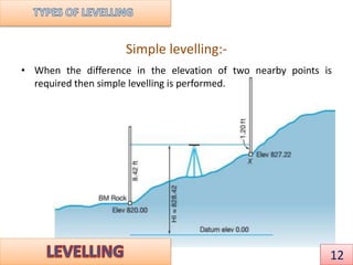
1] Simple levelling
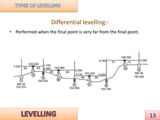
2] Differential levelling
3] Fly levelling
4] Profile levelling
5] Cross sectional levelling
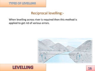
6] Reciprocal levelling
There are two methods for obtaining the elevations at different points:
1] Height of instrument (or plane of collimation) method
2] Rise and fall method
11](https://image.slidesharecdn.com/anandlevellingandcontouring-150825130300-lva1-app6892/85/LEVELING-AND-CONTOURING-11-320.jpg)

![METHODS
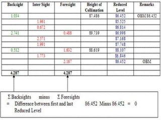
1] Height of Instrument method
• The basic equations are
• Height of instrument for the first setting= RL of BM + BS(at BM)
• Subtract the IS and FS from HI to get RL of intermediate stations
and change points.
• Checking: ΣBS -ΣFS = Last RL –First RL. This is –ve for FALL and +ve
for RISE.
17](https://image.slidesharecdn.com/anandlevellingandcontouring-150825130300-lva1-app6892/85/LEVELING-AND-CONTOURING-17-320.jpg)
![METHODS
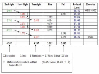
2] Rise and Fall method
• In this method the difference of the present staff reading is
subtracted from the previous staff reading.
• Previous reading –present staff reading = +ve, denotes RISE
• Previous reading –present staff reading = -ve, denotes FALL
• Checking: ΣBS -ΣFS = Last RL –First RL= ΣRise -ΣFall
19](https://image.slidesharecdn.com/anandlevellingandcontouring-150825130300-lva1-app6892/85/LEVELING-AND-CONTOURING-19-320.jpg)
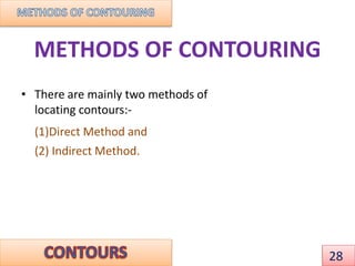
![Ground
level
Back sight
[from dumpy
level]
Height of instrument
[ground level+ back sight
from dumpy level]
Fore sight
[from dumpy
level]
Height of new
point [height of
instrument fore
sight]
Bench
mark
100 9 109 2 107
107 6 113 1 112
Back sight
9 m
Fore sight
2 m
Back sight
6 m
Fore sight
1 m
Level of dumpy=109m
Level of dumpy=113m
9m
100m+
9m
6m
6m+107m
1m
2m
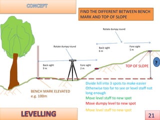
BENCH MARK ELEVATED
e.g. 100m
SO THE DIFFERENCE
IN HEIGHT IS
112-100=12M
22](https://image.slidesharecdn.com/anandlevellingandcontouring-150825130300-lva1-app6892/85/LEVELING-AND-CONTOURING-22-320.jpg)
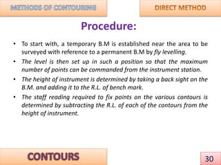
![1] Direct Method:
• In this method, the contours to be
located are directly traced out in the
field by locating and marking a
number of points on each contour.
• These points are then surveyed and
plotted on plan and the contours
drawn through them.
• This method is most accurate but
very slow and tedious as a lot of time
is wasted in searching points of the
same elevation for a contour.
• This is suitable for small area and
where great accuracy is required
29
DIRECT METHOD OF
CONTOURING
50
48
B.M.
46](https://image.slidesharecdn.com/anandlevellingandcontouring-150825130300-lva1-app6892/85/LEVELING-AND-CONTOURING-29-320.jpg)
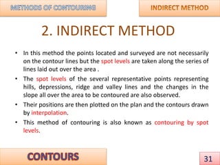
![• This method is commonly employed in all kinds of surveys as this is
cheaper, quicker and less tedious as compared to direct method.
There are mainly three method of contouring in indirect method:
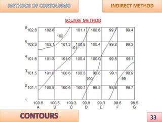
• (I) BY SQUARES [SQUARE METHOD]:-
• In this method, the whole area is divided into number of squares,
the side of which may vary from 5m to 30m depending upon the
nature of the ground and the contour interval. The square need not
be of the same size throughout.
• The corners of the squares are pegged out and the reduced levels
of these points are determined with a level.
32](https://image.slidesharecdn.com/anandlevellingandcontouring-150825130300-lva1-app6892/85/LEVELING-AND-CONTOURING-32-320.jpg)


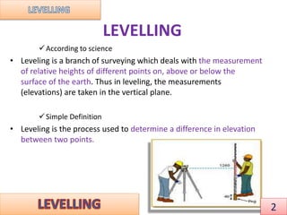
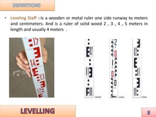
Leveling is a surveying technique used to determine differences in elevation between points. It involves measuring vertical distances between a fixed benchmark and other points using a leveling instrument, leveling rod, and trigonometric leveling. There are two main methods for leveling - the height of instrument method and rise and fall method. Leveling is used to establish elevations, construct contour maps, and determine cut/fill volumes for engineering projects.