Downloaded 1,648 times


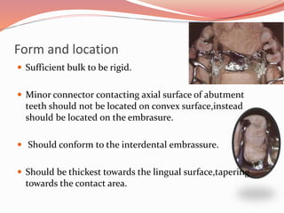
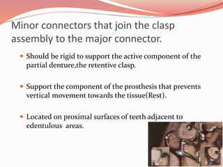
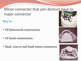
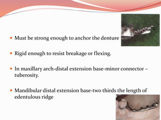
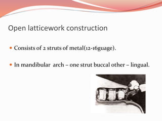
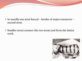
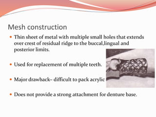

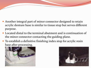
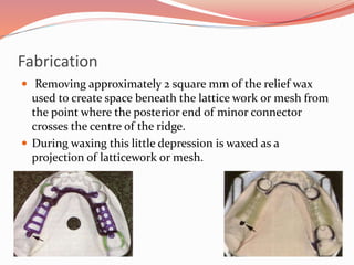
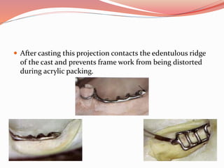
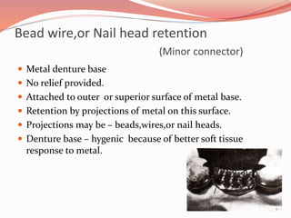


Minor connectors are components that connect parts of a removable partial denture like clasps, retainers, and rests to the major connector or denture base. There are 4 types that connect different components. They distribute forces to prevent excessive stress on any one tooth or ridge area. Minor connectors are usually located in interdental embrasures and have sufficient bulk and rigidity. They come in different designs like latticework, mesh, or beads to securely attach the denture base. Proper form, location, finish lines, and attachment to the major connector are important considerations for minor connectors.


