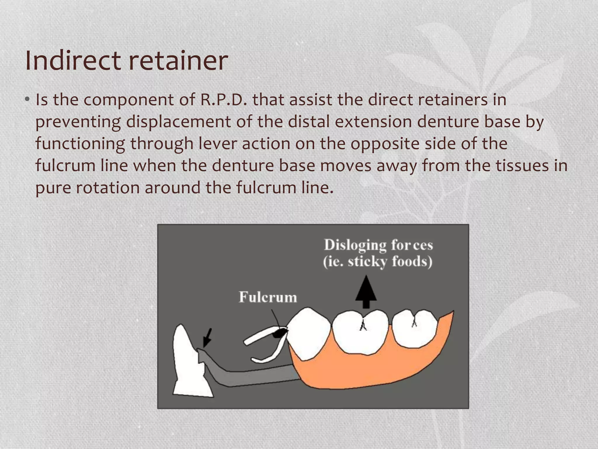
The document discusses the principles and components involved in the construction of removable partial dentures (RPD), including types, indications, retention, stability, support, and various components like major and minor connectors, rests, and direct retainers. It outlines the specific requirements and function of each component, as well as design principles for effective partial denture fabrication. Furthermore, it emphasizes the importance of surveying techniques to ensure proper fitting and function.


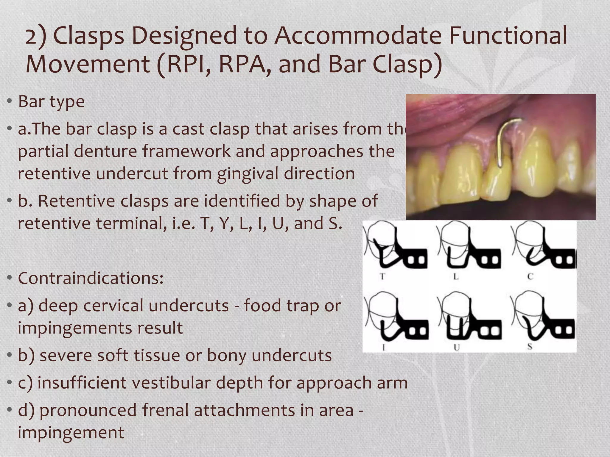
![RPA clasps
• Mesial rest concept clasps have been
proposed to accomplish movement
accommodation by changing the fulcrum
location the RPA consist of [rest, proximal
plate, Akers] the Akers is used instead of I bar
which arises from the proximal plate and end
in mesiobuccal undercut , it used when there
is insufficient vestibular depth or sever tissue
under cut.
• Some advantages are
• (1) its interproximal location, which may be
used to esthetic advantage.
• (2) increased retention without tipping action
on the abutment.
• (3) less chance of accidental distortion
resulting from its proximity to the denture
border.](https://image.slidesharecdn.com/partialdenture-210916051731/75/removable-Partial-denture-41-2048.jpg)