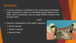
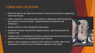
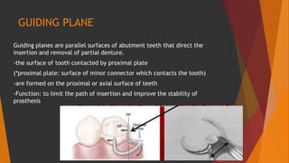
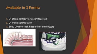
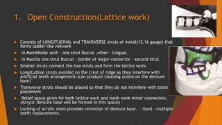
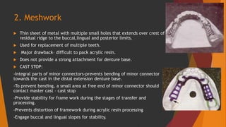
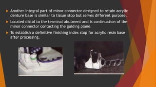
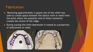
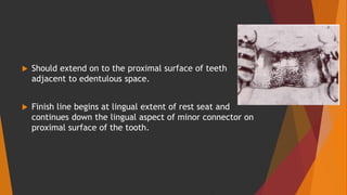
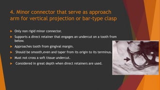
MINOR CONNECTORS
Sambhav Acharya
BDS 1st Batch
KMC
CONTENTS
 INTRODUCTION
 FUNCTION
 FORMS AND LOCATION
 TYPES
DEFINITION
 “A minor connector is defined as the connecting link between
major connector or base of a removable partial denture and
other units of prosthesis, such as clasps indirect retainers and
occlusal rests”
(-GPT)
 Connects components to the major connector
 Direct retainer
 Indirect retainer
 Denture base
FUNCTIONS
 connects the major connector to the other parts like
clasps,rests, indirect retainer and denture bases.
 transmits stresses evenly to all components so that there
is no concentration of load at any single point.
 transmits the force acting on prosthesis to the edentulous
ridge and the remaining natural teeth.
FORMS AND LOCATIONS
 Sufficient bulk to be rigid and transfer of functional stresses to supporting
teeth and tissues.
 Minor connector contacting axial surface of abutment teeth should not
be located on convex surface, instead should be located on the
embrasure.
 Should confirm to the interdental embrassure.
 Should be thickest towards the lingual surface, tapering towards the
contact area.
 Deepest part of interdental embrasure should have been blocked out to
avoid interference during placement and removal,
 When a minor connector contacts tooth surfaces on either side of the
embrassure in which it lies,it should be tapered to the teeth.
 Should form right angle with major connector so that the gingival crossing
is abrupt and covers as little gingival tissue as possible
 Sharp angle should be avoided
 Whenever possible, the minor connector of a removable partial denture is
located in the interdental embrasure.
 Minor connector should be wide enough to use the guiding plane to the
fullest advantage.
GUIDING PLANE
Guiding planes are parallel surfaces of abutment teeth that direct the
insertion and removal of partial denture.
-the surface of tooth contacted by proximal plate
(*proximal plate: surface of minor connector which contacts the tooth)
-are formed on the proximal or axial surface of teeth
-Function: to limit the path of insertion and improve the stability of
prosthesis
TYPES
4 types
1. Minor Connector that joins Clasp Assembly to major connector
2. Joins an indirect retainer or Auxillary Rest to the major connector
3. Joins the Resin Denture Base to the Major Connector
4. Serves as approach arm for Bar type Clasp
1. Minor Connector that joins Clasp
Assembly to major connector
 Should be rigid to support the active component of the partial
denture,the retentive clasp.
 Support the component of the prosthesis that prevents vertical
movement towards the tissue(Rest).
 Located on proximal surfaces of teeth adjacent to edentulous
areas.
 Should be broad buccolingually but thin mesiodistally.
 If clasp assembly is not being placed on a tooth adjacent to an
edentulous space,minor connector must be positioned in
embrassure between two teeth.
 Never position on convex lingual surface of a tooth.
2. Minor Connector that joins an indirect
retainer or Auxillary Rest to the major
connector
 Arises from the major connector.
 Form a right angle with major connector.
 Designed to lie in the embrassure between teeth to
disguise its bulk as much as possible.
3. Minor Connector that Joins the Resin
Denture Base to the Major Connector
 REQUIREMENTS
-Must be strong enough to anchor the denture
base
-Rigid enough to resist breakage or flexing.
-In maxillary arch-distal extension base-minor
connector – tuberosity.
-Mandibular distal extension base-two thirds the
length of edentulous ridge
Available in 3 Forms:
1. Of Open (latticework) construction
2. Of mesh construction
3. Bead ,wire,or nail head minor connectors
1. Open Construction(Lattice work)
 Consists of LONGITUDINAL and TRANSVERSE struts of metal(12,16 gauge) that
forms ladder like network
 In Mandibular arch – one strut Buccal ,other – Lingual.
 In Maxilla one strut Buccal – border of major connector – second strut.
 Smaller struts connect the two struts and form the lattice work.
 Longitudinal struts avoided on the crest of ridge as they interfere with
artificial teeth arrangement.(can produce cleaving action on the denture
base)
 Transverse struts should be placed so that they do not interfere with tooth
placement
 Relief space given for both lattice work and mesh work minor connectors.
(Acrylic denture base will be formed in this space) 
 Locking of acrylic resin provides retention of denture base.  Used – multiple
teeth replacements.
2. Meshwork
 Thin sheet of metal with multiple small holes that extends over crest of
residual ridge to the buccal,lingual and posterior limits.
 Used for replacement of multiple teeth.
 Major drawback– difficult to pack acrylic resin.
 Does not provide a strong attachment for denture base.
 CAST STOP:
-Integral parts of minor connectors-prevents bending of minor connector
towards the cast in the distal extension denture base.
-To prevent bending, a small area at free end of minor connector should
contact master cast – cast stop
-Provide stability for frame work during the stages of transfer and
processing.
-Prevents distortion of framework during acrylic resin processing
-Engage buccal and lingual slopes for stability.
 Another integral part of minor connector designed to retain acrylic
denture base is similar to tissue stop but serves different purpose.
 Located distal to the terminal abutment and is continuation of the
minor connector contacting the guiding plane.
 To establish a definitive finishing index stop for acrylic resin base
after processing.
Fabrication
 Removing approximately 2 square mm of the relief wax
used to create space beneath the lattice work or mesh from
the point where the posterior end of minor connector
crosses the centre of the ridge.
 During waxing this little depression is waxed as a projection
of latticework or mesh.
 After casting this projection contacts the edentulous ridge
of the cast and prevents frame work from being distorted
during acrylic packing.
Bead wire,or Nail head retention
(Minor connector)
 Metal denture base
 No relief provided.
 Attached to outer or superior surface of metal base.
 Retention by projections of metal on this surface.
 Projections may be – beads,wires,or nail heads.
 Denture base – hygenic because of better soft tissue
response to metal.
Shortcomings –
 Difficult to adjust metal base.
 Cannot be adequately relined.
 Weakest attachment of 3 types.
“Should be used on tooth-supported,well healed ridges when interarch space is
limited.”
Attachment to major connector
 Acrylic resin minor connector must be joined to major
connector with sufficient bulk to avoid fracture.
 Must join in a smooth,event joint.
 Irregularity between surface irritates tongue or mucosa of
the ridge.
 Acrylic resin– butt joint must be made on both internal
and external surfaces of the major connector.
 For metal base minor connector – single butt joint .
 Butt joints – finish lines.
 Outer aspect – external finish line.
 Internal or tissue side – internal finish line.
Finish lines
 Finishing line junction with major connector– angle not
greater than 90 degree.
 Finish line located too far medially– natural contour of
palate altered by thickness of acrylic resin.
 Too far buccally– difficult to create a natural contour of
acrylic resin on lingual surface of artificial teeth.
 90 degree butt-type joint given for junction of minor
connectors and bar-type direct retainers.
Internal finish lines
 Formed from relief waxes used over edentulous ridge on
master cast.
 24-26 guage thick.
 Margins of relief wax – internal finish line.
 Ledge created by wax – sharp and define
External finish lines
 Sharp and definite and should be slightly undercut to help lock
acrylic resin securely to major connector.
 Angle the finish line forms with major connector – less than 90
degree.
 Should extend on to the proximal surface of teeth
adjacent to edentulous space.
 Finish line begins at lingual extent of rest seat and
continues down the lingual aspect of minor connector on
proximal surface of the tooth.
4. Minor connector that serve as approach
arm for vertical projection or bar-type clasp
 Only non rigid minor connector.
 Supports a direct retainer that engages an undercut on a tooth from
below.
 Approaches tooth from gingival margin.
 Should be smooth,even and taper from its origin to its terminus.
 Must not cross a soft tissue undercut.
 Considered in great depth when direct retainers are used.
References
 ‘Textbook of Prosthodontics-Deepak Nallaswamy’
 ‘Stewart’s Clinical Removable Partial Prosthodontics’

Minor connectors

  • 1.
  • 2.
    CONTENTS  INTRODUCTION  FUNCTION FORMS AND LOCATION  TYPES
  • 3.
    DEFINITION  “A minorconnector is defined as the connecting link between major connector or base of a removable partial denture and other units of prosthesis, such as clasps indirect retainers and occlusal rests” (-GPT)  Connects components to the major connector  Direct retainer  Indirect retainer  Denture base
  • 4.
    FUNCTIONS  connects themajor connector to the other parts like clasps,rests, indirect retainer and denture bases.  transmits stresses evenly to all components so that there is no concentration of load at any single point.  transmits the force acting on prosthesis to the edentulous ridge and the remaining natural teeth.
  • 5.
    FORMS AND LOCATIONS Sufficient bulk to be rigid and transfer of functional stresses to supporting teeth and tissues.  Minor connector contacting axial surface of abutment teeth should not be located on convex surface, instead should be located on the embrasure.  Should confirm to the interdental embrassure.  Should be thickest towards the lingual surface, tapering towards the contact area.  Deepest part of interdental embrasure should have been blocked out to avoid interference during placement and removal,  When a minor connector contacts tooth surfaces on either side of the embrassure in which it lies,it should be tapered to the teeth.
  • 6.
     Should formright angle with major connector so that the gingival crossing is abrupt and covers as little gingival tissue as possible  Sharp angle should be avoided  Whenever possible, the minor connector of a removable partial denture is located in the interdental embrasure.  Minor connector should be wide enough to use the guiding plane to the fullest advantage.
  • 7.
    GUIDING PLANE Guiding planesare parallel surfaces of abutment teeth that direct the insertion and removal of partial denture. -the surface of tooth contacted by proximal plate (*proximal plate: surface of minor connector which contacts the tooth) -are formed on the proximal or axial surface of teeth -Function: to limit the path of insertion and improve the stability of prosthesis
  • 8.
    TYPES 4 types 1. MinorConnector that joins Clasp Assembly to major connector 2. Joins an indirect retainer or Auxillary Rest to the major connector 3. Joins the Resin Denture Base to the Major Connector 4. Serves as approach arm for Bar type Clasp
  • 10.
    1. Minor Connectorthat joins Clasp Assembly to major connector  Should be rigid to support the active component of the partial denture,the retentive clasp.  Support the component of the prosthesis that prevents vertical movement towards the tissue(Rest).  Located on proximal surfaces of teeth adjacent to edentulous areas.  Should be broad buccolingually but thin mesiodistally.  If clasp assembly is not being placed on a tooth adjacent to an edentulous space,minor connector must be positioned in embrassure between two teeth.  Never position on convex lingual surface of a tooth.
  • 11.
    2. Minor Connectorthat joins an indirect retainer or Auxillary Rest to the major connector  Arises from the major connector.  Form a right angle with major connector.  Designed to lie in the embrassure between teeth to disguise its bulk as much as possible.
  • 12.
    3. Minor Connectorthat Joins the Resin Denture Base to the Major Connector  REQUIREMENTS -Must be strong enough to anchor the denture base -Rigid enough to resist breakage or flexing. -In maxillary arch-distal extension base-minor connector – tuberosity. -Mandibular distal extension base-two thirds the length of edentulous ridge
  • 13.
    Available in 3Forms: 1. Of Open (latticework) construction 2. Of mesh construction 3. Bead ,wire,or nail head minor connectors
  • 14.
    1. Open Construction(Latticework)  Consists of LONGITUDINAL and TRANSVERSE struts of metal(12,16 gauge) that forms ladder like network  In Mandibular arch – one strut Buccal ,other – Lingual.  In Maxilla one strut Buccal – border of major connector – second strut.  Smaller struts connect the two struts and form the lattice work.  Longitudinal struts avoided on the crest of ridge as they interfere with artificial teeth arrangement.(can produce cleaving action on the denture base)  Transverse struts should be placed so that they do not interfere with tooth placement  Relief space given for both lattice work and mesh work minor connectors. (Acrylic denture base will be formed in this space)   Locking of acrylic resin provides retention of denture base.  Used – multiple teeth replacements.
  • 15.
    2. Meshwork  Thinsheet of metal with multiple small holes that extends over crest of residual ridge to the buccal,lingual and posterior limits.  Used for replacement of multiple teeth.  Major drawback– difficult to pack acrylic resin.  Does not provide a strong attachment for denture base.  CAST STOP: -Integral parts of minor connectors-prevents bending of minor connector towards the cast in the distal extension denture base. -To prevent bending, a small area at free end of minor connector should contact master cast – cast stop -Provide stability for frame work during the stages of transfer and processing. -Prevents distortion of framework during acrylic resin processing -Engage buccal and lingual slopes for stability.
  • 16.
     Another integralpart of minor connector designed to retain acrylic denture base is similar to tissue stop but serves different purpose.  Located distal to the terminal abutment and is continuation of the minor connector contacting the guiding plane.  To establish a definitive finishing index stop for acrylic resin base after processing.
  • 17.
    Fabrication  Removing approximately2 square mm of the relief wax used to create space beneath the lattice work or mesh from the point where the posterior end of minor connector crosses the centre of the ridge.  During waxing this little depression is waxed as a projection of latticework or mesh.
  • 18.
     After castingthis projection contacts the edentulous ridge of the cast and prevents frame work from being distorted during acrylic packing.
  • 19.
    Bead wire,or Nailhead retention (Minor connector)  Metal denture base  No relief provided.  Attached to outer or superior surface of metal base.  Retention by projections of metal on this surface.  Projections may be – beads,wires,or nail heads.  Denture base – hygenic because of better soft tissue response to metal.
  • 20.
    Shortcomings –  Difficultto adjust metal base.  Cannot be adequately relined.  Weakest attachment of 3 types. “Should be used on tooth-supported,well healed ridges when interarch space is limited.”
  • 21.
    Attachment to majorconnector  Acrylic resin minor connector must be joined to major connector with sufficient bulk to avoid fracture.  Must join in a smooth,event joint.  Irregularity between surface irritates tongue or mucosa of the ridge.  Acrylic resin– butt joint must be made on both internal and external surfaces of the major connector.
  • 22.
     For metalbase minor connector – single butt joint .  Butt joints – finish lines.  Outer aspect – external finish line.  Internal or tissue side – internal finish line.
  • 23.
    Finish lines  Finishingline junction with major connector– angle not greater than 90 degree.  Finish line located too far medially– natural contour of palate altered by thickness of acrylic resin.
  • 24.
     Too farbuccally– difficult to create a natural contour of acrylic resin on lingual surface of artificial teeth.  90 degree butt-type joint given for junction of minor connectors and bar-type direct retainers.
  • 25.
    Internal finish lines Formed from relief waxes used over edentulous ridge on master cast.  24-26 guage thick.  Margins of relief wax – internal finish line.  Ledge created by wax – sharp and define
  • 26.
    External finish lines Sharp and definite and should be slightly undercut to help lock acrylic resin securely to major connector.  Angle the finish line forms with major connector – less than 90 degree.
  • 27.
     Should extendon to the proximal surface of teeth adjacent to edentulous space.  Finish line begins at lingual extent of rest seat and continues down the lingual aspect of minor connector on proximal surface of the tooth.
  • 28.
    4. Minor connectorthat serve as approach arm for vertical projection or bar-type clasp  Only non rigid minor connector.  Supports a direct retainer that engages an undercut on a tooth from below.  Approaches tooth from gingival margin.  Should be smooth,even and taper from its origin to its terminus.  Must not cross a soft tissue undercut.  Considered in great depth when direct retainers are used.
  • 29.
    References  ‘Textbook ofProsthodontics-Deepak Nallaswamy’  ‘Stewart’s Clinical Removable Partial Prosthodontics’