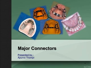
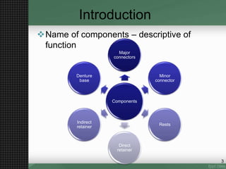
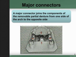
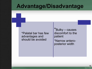
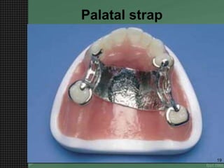
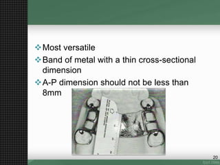
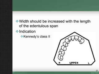
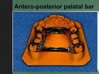
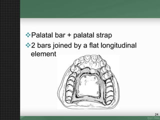
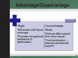
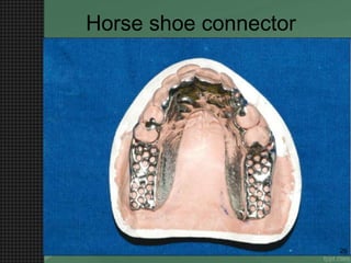
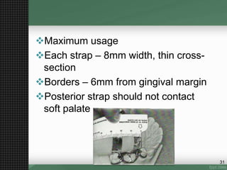
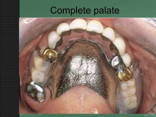
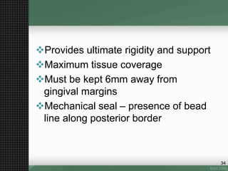
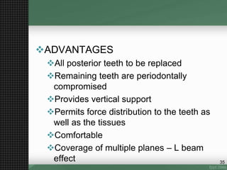
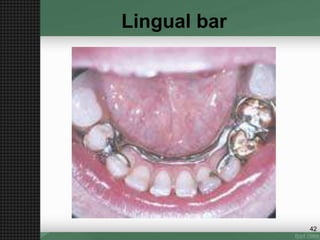
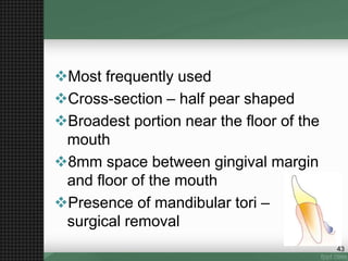
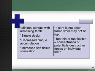
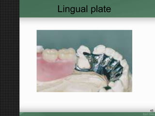
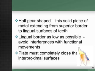
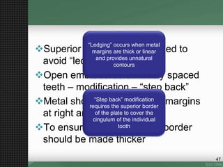
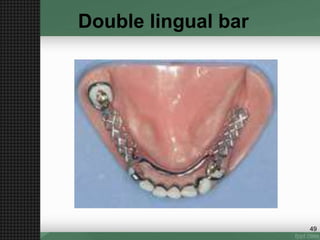
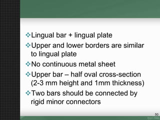
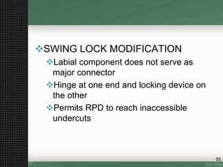
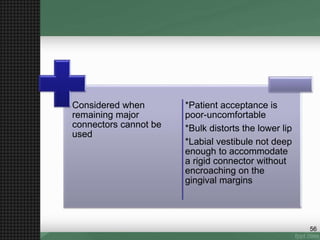
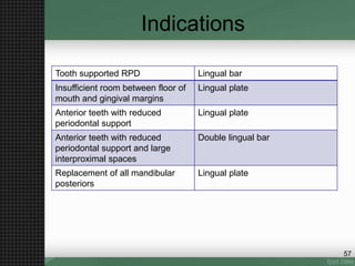
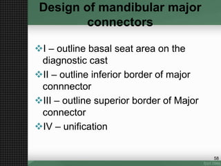
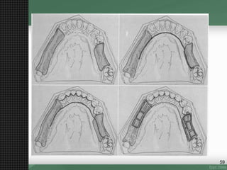
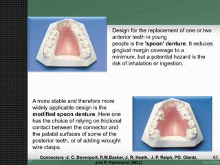
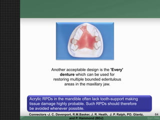
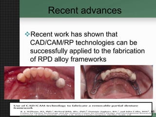
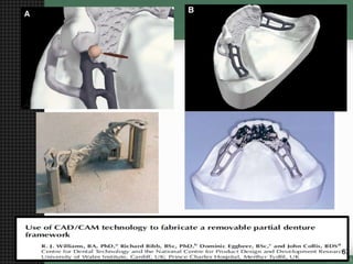
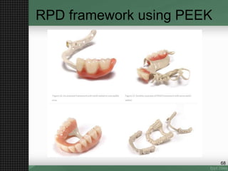
Major Connectors
Presented by :
Apurva Thampi
1
Contents
Introduction
Major connectors
Role of major connectors
Types of maxillary major connectors
Review of indications
Steps in Designing
Types of Mandibular major connectors
Review of indications
Steps in Designing
Recent advances
Conclusion
References
2
Introduction
Name of components – descriptive of
function
Components
Major
connectors
Minor
connector
Rests
Direct
retainer
Indirect
retainer
Denture
base
3
Contents
Introduction
Major connectors
Role of major connectors
Types of maxillary major connectors
Review of indications
Steps in Designing
Types of Mandibular major connectors
Review of indications
Steps in Designing
Recent advances
Conclusion
References
4
Major connectors
A major connector joins the components of
the removable partial denture from one side of
the arch to the opposite side
5
Contents
Introduction
Major connectors
Role of major connectors
Types of maxillary major connectors
Review of indications
Steps in Designing
Types of Mandibular major connectors
Review of indications
Steps in Designing
Recent advances
Conclusion
References
6
Role of major connectors
Be rigid
Protect the associated soft tissue
Provide means for obtaining indirect
retention
Provide a means of placement of denture
base
Promote patient comfort
Self cleansing
7
Rigidity :
Permits broad distribution of
forces
Protect soft tissue:
Maxillary connector – 6mm
from marginal gingiva
Mandibular connector –
3mm from marginal gingiva
8
Provide means of
indirect retention:
By use of indirect retainers,
rotation around the fulcrum
line can be prevented
Promote patient
comfort:
Edges should be contoured
9
Major connector is based on the
principle of leverage
10
It will limit movement possibilities by acting
as a counter-acting lever
CROSS-ARCH STABILITY
Major
connectors
11
Requirements of maxillary major
connectors
Borders – 6mm from gingival margins
Anterior border should blend with the
palatal anatomy
Borders should cross the margins at right
angles
Palatal strap – 8mm wide
Open central connectors – medial borders
should be located at the junction of
horizontal and vertical surfaces
12
Thickness of the plate should be uniform
Borders should be gently curved
Intaglio surface should not be highly
polished
13
Contents
Introduction
Major connectors
Role of major connectors
Types of maxillary major connectors
Review of indications
Steps in Designing
Types of Mandibular major connectors
Review of indications
Steps in Designing
Recent advances
Conclusion
References
14
Types of Maxillary major
connectors
• Palatal bar
• Palatal strap
• Antero-posterior palatal bar
• Horse-shoe shaped
• Antero-posterior palatal
strap
• Complete palate
6 types of
maxillary
major
connectors
15
Palatal bar
16
Narrow, half oval
Thickest point at the centre
Gentle curved and should not form an
angle
Indications
 class III (short span)
application
17
18
*Palatal bar has few
advantages and
should be avoided
*Bulky – causes
discomfort to the
patient
*Narrow antero-
posterior width
Advantage/Disadvantage
Palatal strap
19
Most versatile
Band of metal with a thin cross-sectional
dimension
A-P dimension should not be less than
8mm
20
Width should be increased with the length
of the edentulous span
Indication
Kennedy’s class II
21
22
*Increased resistance
to bending and
twisting forces
*can be kept thin
*little interference with
normal tongue action
*increased tissue
coverage
*Excessive palatal
coverage
* Anterior border
should be positioned
posterior to rugae
* Prone to papillary
hyperplasia
Advantage/Disadvantage
Antero-posterior palatal bar
23
Palatal bar + palatal strap
2 bars joined by a flat longitudinal
element
24
Advantage/Disadvantage
*Rigid
*Minimises soft tissue
coverage
*Provides exceptional
resistance to
deformation
*Uncomfortable
*Bulky
*Derives little support
from bony tissue
*Contraindication –
reduced periodontal
support
25
Horse shoe connector
26
Consists of a thin band of metal
Lingual surface of remaining teeth to
palatal tissue – 6-8 mm
Should be symmetrical – equal height
on both sides
27
Advantage/Disadvantage
*Strong connector
*Derives some
vertical support from
tissues of hard palate
*Designed to avoid
bony prominences
Tendency to deform
Does not provide
cross-arch
stabilisation
Should be considered
only if more rigid
connectors cannot be
used
28
Horse shoe major connector has a tendency to
Flex or deform. Hence it is not a good connector
When cross arch stabilization in required.
29
Antero-posterior palatal strap
30
Maximum usage
Each strap – 8mm width, thin cross-
section
Borders – 6mm from gingival margin
Posterior strap should not contact
soft palate
31
Advantage/Disadvantage
*Derives good
support from hard
tissues
*L-beam effect –
increases
resistance to
flexure
+Extensive length
of borders may
cause irritation to
the tongue
32
Complete palate
33
Provides ultimate rigidity and support
Maximum tissue coverage
Must be kept 6mm away from
gingival margins
Mechanical seal – presence of bead
line along posterior border
34
ADVANTAGES
All posterior teeth to be replaced
Remaining teeth are periodontally
compromised
Provides vertical support
Permits force distribution to the teeth as
well as the tissues
Comfortable
Coverage of multiple planes – L beam
effect 35
DISADVANTAGES
Adverse soft tissue reaction may occur
– soft tissue hyperplasia – poor oral
hygiene and prolonged periods of
denture wearing
36
Indications
Case Type of major connector
Weak periodontal support Wide palatal strap or complete
palate
Adequate periodontal support Palatal strap or A-P palatal strap
Long-span distal extension A-P palatal strap or complete
palate
Anterior teeth to be replaced A-P palatal strap, complete palate
or horseshoe major connector
Presence of torus A-P palatal strap, A-P palatal bar,
horse shoe connector
37
Design of maxillary major
connectors
:
Outline
primary
stress
bearing
areas
Outline
non
bearing
areas
Outline of
connector
areas
Selection
of
connector
type
Unification
38
Requirements of mandibular
major connectors
Rigid without being bulky
Must not impinge on the movable
floor of the mouth
Relief required between the rigid
metal connector and underlying
tissues
39
Contents
Introduction
Major connectors
Role of major connectors
Types of maxillary major connectors
Review of indications
Steps in Designing
Types of Mandibular major connectors
Review of indications
Steps in Designing
Recent advances
Conclusion
References
40
Types of mandibular major
connectors
• Lingual bar
• Lingual plate
• Double lingual
bar
• Labial bar
4 types of
mandibular
major
connectors
41
Lingual bar
42
Most frequently used
Cross-section – half pear shaped
Broadest portion near the floor of the
mouth
8mm space between gingival margin
and floor of the mouth
Presence of mandibular tori –
surgical removal
43
*Minimal contact with
remaining teeth
*Simple design
*Decreased plaque
accumulation
*Increased soft tissue
stimulation
*If care is not taken,
frame work may not be
rigid
*Too thin or too flexible
– concentration of
potentially destructive
forces on individual
teeth
44
Lingual plate
45
Half pear shaped – this solid piece of
metal extending from superior border
to lingual surfaces of teeth
Lingual border as low as possible -
avoid interferences with functional
movements
Plate must completely close the
interproximal surfaces
46
Superior border is knife-edged to
avoid “ledging”
Open embrasures or widely spaced
teeth – modification – “step back”
Metal should cross gingival margins
at right angles
To ensure rigidity – inferior border
should be made thicker
“Ledging” occurs when metal
margins are thick or linear
and provides unnatural
contours
“Step back” modification
requires the superior border
of the plate to cover the
cingulum of the individual
tooth
47
*Exceptional rigidity – des
not interfere with functional
movements
*Stabilize periodontally
weak teeth
*May provide additional
indirect retention
*If mandibular tori cannot be
removed, adequate relief
should be provided
*Extensive coverage –
decalcification of enamel
*Irritation of tissues in
patients with poor oral
hygiene
48
Double lingual bar
49
Lingual bar + lingual plate
Upper and lower borders are similar
to lingual plate
No continuous metal sheet
Upper bar – half oval cross-section
(2-3 mm height and 1mm thickness)
Two bars should be connected by
rigid minor connectors
50
Rests should be placed at each end
of the bar – no further posterior than
1st premolar
51
*Effectively
extends indirect
retention in an
anterior direction
*Free flow of
saliva – marginal
gingiva stimulation
Tendency to trap
debris
Uncomfortable –
multiple borders
and thickness
52
Labial bar
53
Runs across mucosa on facial
surface
Half pear shaped
Longer than lingual bar
Height and thickness must be greater
Successful treatment very limited
54
SWING LOCK MODIFICATION
Labial component does not serve as
major connector
Hinge at one end and locking device on
the other
Permits RPD to reach inaccessible
undercuts
55
Considered when
remaining major
connectors cannot be
used
*Patient acceptance is
poor-uncomfortable
*Bulk distorts the lower lip
*Labial vestibule not deep
enough to accommodate
a rigid connector without
encroaching on the
gingival margins
56
Indications
Tooth supported RPD Lingual bar
Insufficient room between floor of
mouth and gingival margins
Lingual plate
Anterior teeth with reduced
periodontal support
Lingual plate
Anterior teeth with reduced
periodontal support and large
interproximal spaces
Double lingual bar
Replacement of all mandibular
posteriors
Lingual plate
57
Design of mandibular major
connectors
I – outline basal seat area on the
diagnostic cast
II – outline inferior border of major
connnector
III – outline superior border of Major
connector
IV – unification
58
59
Contents
Introduction
Major connectors
Role of major connectors
Types of maxillary major connectors
Review of indications
Steps in Designing
Types of Mandibular major connectors
Review of indications
Steps in Designing
Acrylic dentures
Recent advances
Conclusion
References 60
Acrylic dentures
Most commonly used
Indicated when the life of the denture
is expected to be less
Or if relining may be necessary
Weaker and less rigid than the metal
alloys - more likely to flex or fracture
during function.
61Connectors -J. C. Davenport, R.M.Basker, J. R. Heath, J. P. Ralph, PO. Glantz,
and P. Hammond (BDJ)
INDICATIONS
During the phase or rapid bone
resorption after tooth loss
When remaining teeth have poor
prognosis, and an extraction and
replacement is expected
Interim denture
In growing individuals
62Connectors -J. C. Davenport, R.M.Basker, J. R. Heath, J. P. Ralph, PO. Glantz,
and P. Hammond (BDJ)
Design for the replacement of one or two
anterior teeth in young
people is the 'spoon' denture. It reduces
gingival margin coverage to a
minimum, but a potential hazard is the
risk of inhalation or ingestion.
A more stable and therefore more
widely applicable design is the
modified spoon denture. Here one
has the choice of relying on frictional
contact between the connector and
the palatal surfaces of some of the
posterior teeth, or of adding wrought
wire clasps.
63Connectors -J. C. Davenport, R.M.Basker, J. R. Heath, J. P. Ralph, PO. Glantz,
and P. Hammond (BDJ)
Another acceptable design is the 'Every'
denture which can be used for
restoring multiple bounded edentulous
areas in the maxillary jaw.
Acrylic RPDs in the mandible often lack tooth-support making
tissue damage highly probable. Such RPDs should therefore
be avoided whenever possible.
64Connectors -J. C. Davenport, R.M.Basker, J. R. Heath, J. P. Ralph, PO. Glantz,
and P. Hammond (BDJ)
Contents
Introduction
Major connectors
Role of major connectors
Types of maxillary major connectors
Review of indications
Steps in Designing
Types of Mandibular major connectors
Review of indications
Steps in Designing
Acrylic dentures
Recent advances
Conclusion
References 65
Recent advances
Recent work has shown that
CAD/CAM/RP technologies can be
successfully applied to the fabrication
of RPD alloy frameworks
66
67
RPD framework using PEEK
68
To conclude….
69
Bibliography
 McCracken’s removable partial prosthodontics –
12th edition
 Stewarts removable partial prosthodontics – 4th
edition
 Partial dentures – John osborne and George
Lammie – 4th edition
 Connectors -J. C. Davenport, R.M.Basker, J. R. Heath, J. P.
Ralph, PO. Glantz, and P. Hammond (BDJ)
 Use of CAD/CAM technology to fabricate a
removable partial denture framework (R. J. Williams, BA,
PhD,a Richard Bibb, BSc, PhD,b Dominic Eggbeer, BSc,c and John Collis,
BDS) (JPD)
70
Thank you!!
71

Major Connectors

  • 1.
  • 2.
    Contents Introduction Major connectors Role ofmajor connectors Types of maxillary major connectors Review of indications Steps in Designing Types of Mandibular major connectors Review of indications Steps in Designing Recent advances Conclusion References 2
  • 3.
    Introduction Name of components– descriptive of function Components Major connectors Minor connector Rests Direct retainer Indirect retainer Denture base 3
  • 4.
    Contents Introduction Major connectors Role ofmajor connectors Types of maxillary major connectors Review of indications Steps in Designing Types of Mandibular major connectors Review of indications Steps in Designing Recent advances Conclusion References 4
  • 5.
    Major connectors A majorconnector joins the components of the removable partial denture from one side of the arch to the opposite side 5
  • 6.
    Contents Introduction Major connectors Role ofmajor connectors Types of maxillary major connectors Review of indications Steps in Designing Types of Mandibular major connectors Review of indications Steps in Designing Recent advances Conclusion References 6
  • 7.
    Role of majorconnectors Be rigid Protect the associated soft tissue Provide means for obtaining indirect retention Provide a means of placement of denture base Promote patient comfort Self cleansing 7
  • 8.
    Rigidity : Permits broaddistribution of forces Protect soft tissue: Maxillary connector – 6mm from marginal gingiva Mandibular connector – 3mm from marginal gingiva 8
  • 9.
    Provide means of indirectretention: By use of indirect retainers, rotation around the fulcrum line can be prevented Promote patient comfort: Edges should be contoured 9
  • 10.
    Major connector isbased on the principle of leverage 10 It will limit movement possibilities by acting as a counter-acting lever CROSS-ARCH STABILITY
  • 11.
  • 12.
    Requirements of maxillarymajor connectors Borders – 6mm from gingival margins Anterior border should blend with the palatal anatomy Borders should cross the margins at right angles Palatal strap – 8mm wide Open central connectors – medial borders should be located at the junction of horizontal and vertical surfaces 12
  • 13.
    Thickness of theplate should be uniform Borders should be gently curved Intaglio surface should not be highly polished 13
  • 14.
    Contents Introduction Major connectors Role ofmajor connectors Types of maxillary major connectors Review of indications Steps in Designing Types of Mandibular major connectors Review of indications Steps in Designing Recent advances Conclusion References 14
  • 15.
    Types of Maxillarymajor connectors • Palatal bar • Palatal strap • Antero-posterior palatal bar • Horse-shoe shaped • Antero-posterior palatal strap • Complete palate 6 types of maxillary major connectors 15
  • 16.
  • 17.
    Narrow, half oval Thickestpoint at the centre Gentle curved and should not form an angle Indications  class III (short span) application 17
  • 18.
    18 *Palatal bar hasfew advantages and should be avoided *Bulky – causes discomfort to the patient *Narrow antero- posterior width Advantage/Disadvantage
  • 19.
  • 20.
    Most versatile Band ofmetal with a thin cross-sectional dimension A-P dimension should not be less than 8mm 20
  • 21.
    Width should beincreased with the length of the edentulous span Indication Kennedy’s class II 21
  • 22.
    22 *Increased resistance to bendingand twisting forces *can be kept thin *little interference with normal tongue action *increased tissue coverage *Excessive palatal coverage * Anterior border should be positioned posterior to rugae * Prone to papillary hyperplasia Advantage/Disadvantage
  • 23.
  • 24.
    Palatal bar +palatal strap 2 bars joined by a flat longitudinal element 24
  • 25.
    Advantage/Disadvantage *Rigid *Minimises soft tissue coverage *Providesexceptional resistance to deformation *Uncomfortable *Bulky *Derives little support from bony tissue *Contraindication – reduced periodontal support 25
  • 26.
  • 27.
    Consists of athin band of metal Lingual surface of remaining teeth to palatal tissue – 6-8 mm Should be symmetrical – equal height on both sides 27
  • 28.
    Advantage/Disadvantage *Strong connector *Derives some verticalsupport from tissues of hard palate *Designed to avoid bony prominences Tendency to deform Does not provide cross-arch stabilisation Should be considered only if more rigid connectors cannot be used 28
  • 29.
    Horse shoe majorconnector has a tendency to Flex or deform. Hence it is not a good connector When cross arch stabilization in required. 29
  • 30.
  • 31.
    Maximum usage Each strap– 8mm width, thin cross- section Borders – 6mm from gingival margin Posterior strap should not contact soft palate 31
  • 32.
    Advantage/Disadvantage *Derives good support fromhard tissues *L-beam effect – increases resistance to flexure +Extensive length of borders may cause irritation to the tongue 32
  • 33.
  • 34.
    Provides ultimate rigidityand support Maximum tissue coverage Must be kept 6mm away from gingival margins Mechanical seal – presence of bead line along posterior border 34
  • 35.
    ADVANTAGES All posterior teethto be replaced Remaining teeth are periodontally compromised Provides vertical support Permits force distribution to the teeth as well as the tissues Comfortable Coverage of multiple planes – L beam effect 35
  • 36.
    DISADVANTAGES Adverse soft tissuereaction may occur – soft tissue hyperplasia – poor oral hygiene and prolonged periods of denture wearing 36
  • 37.
    Indications Case Type ofmajor connector Weak periodontal support Wide palatal strap or complete palate Adequate periodontal support Palatal strap or A-P palatal strap Long-span distal extension A-P palatal strap or complete palate Anterior teeth to be replaced A-P palatal strap, complete palate or horseshoe major connector Presence of torus A-P palatal strap, A-P palatal bar, horse shoe connector 37
  • 38.
    Design of maxillarymajor connectors : Outline primary stress bearing areas Outline non bearing areas Outline of connector areas Selection of connector type Unification 38
  • 39.
    Requirements of mandibular majorconnectors Rigid without being bulky Must not impinge on the movable floor of the mouth Relief required between the rigid metal connector and underlying tissues 39
  • 40.
    Contents Introduction Major connectors Role ofmajor connectors Types of maxillary major connectors Review of indications Steps in Designing Types of Mandibular major connectors Review of indications Steps in Designing Recent advances Conclusion References 40
  • 41.
    Types of mandibularmajor connectors • Lingual bar • Lingual plate • Double lingual bar • Labial bar 4 types of mandibular major connectors 41
  • 42.
  • 43.
    Most frequently used Cross-section– half pear shaped Broadest portion near the floor of the mouth 8mm space between gingival margin and floor of the mouth Presence of mandibular tori – surgical removal 43
  • 44.
    *Minimal contact with remainingteeth *Simple design *Decreased plaque accumulation *Increased soft tissue stimulation *If care is not taken, frame work may not be rigid *Too thin or too flexible – concentration of potentially destructive forces on individual teeth 44
  • 45.
  • 46.
    Half pear shaped– this solid piece of metal extending from superior border to lingual surfaces of teeth Lingual border as low as possible - avoid interferences with functional movements Plate must completely close the interproximal surfaces 46
  • 47.
    Superior border isknife-edged to avoid “ledging” Open embrasures or widely spaced teeth – modification – “step back” Metal should cross gingival margins at right angles To ensure rigidity – inferior border should be made thicker “Ledging” occurs when metal margins are thick or linear and provides unnatural contours “Step back” modification requires the superior border of the plate to cover the cingulum of the individual tooth 47
  • 48.
    *Exceptional rigidity –des not interfere with functional movements *Stabilize periodontally weak teeth *May provide additional indirect retention *If mandibular tori cannot be removed, adequate relief should be provided *Extensive coverage – decalcification of enamel *Irritation of tissues in patients with poor oral hygiene 48
  • 49.
  • 50.
    Lingual bar +lingual plate Upper and lower borders are similar to lingual plate No continuous metal sheet Upper bar – half oval cross-section (2-3 mm height and 1mm thickness) Two bars should be connected by rigid minor connectors 50
  • 51.
    Rests should beplaced at each end of the bar – no further posterior than 1st premolar 51
  • 52.
    *Effectively extends indirect retention inan anterior direction *Free flow of saliva – marginal gingiva stimulation Tendency to trap debris Uncomfortable – multiple borders and thickness 52
  • 53.
  • 54.
    Runs across mucosaon facial surface Half pear shaped Longer than lingual bar Height and thickness must be greater Successful treatment very limited 54
  • 55.
    SWING LOCK MODIFICATION Labialcomponent does not serve as major connector Hinge at one end and locking device on the other Permits RPD to reach inaccessible undercuts 55
  • 56.
    Considered when remaining major connectorscannot be used *Patient acceptance is poor-uncomfortable *Bulk distorts the lower lip *Labial vestibule not deep enough to accommodate a rigid connector without encroaching on the gingival margins 56
  • 57.
    Indications Tooth supported RPDLingual bar Insufficient room between floor of mouth and gingival margins Lingual plate Anterior teeth with reduced periodontal support Lingual plate Anterior teeth with reduced periodontal support and large interproximal spaces Double lingual bar Replacement of all mandibular posteriors Lingual plate 57
  • 58.
    Design of mandibularmajor connectors I – outline basal seat area on the diagnostic cast II – outline inferior border of major connnector III – outline superior border of Major connector IV – unification 58
  • 59.
  • 60.
    Contents Introduction Major connectors Role ofmajor connectors Types of maxillary major connectors Review of indications Steps in Designing Types of Mandibular major connectors Review of indications Steps in Designing Acrylic dentures Recent advances Conclusion References 60
  • 61.
    Acrylic dentures Most commonlyused Indicated when the life of the denture is expected to be less Or if relining may be necessary Weaker and less rigid than the metal alloys - more likely to flex or fracture during function. 61Connectors -J. C. Davenport, R.M.Basker, J. R. Heath, J. P. Ralph, PO. Glantz, and P. Hammond (BDJ)
  • 62.
    INDICATIONS During the phaseor rapid bone resorption after tooth loss When remaining teeth have poor prognosis, and an extraction and replacement is expected Interim denture In growing individuals 62Connectors -J. C. Davenport, R.M.Basker, J. R. Heath, J. P. Ralph, PO. Glantz, and P. Hammond (BDJ)
  • 63.
    Design for thereplacement of one or two anterior teeth in young people is the 'spoon' denture. It reduces gingival margin coverage to a minimum, but a potential hazard is the risk of inhalation or ingestion. A more stable and therefore more widely applicable design is the modified spoon denture. Here one has the choice of relying on frictional contact between the connector and the palatal surfaces of some of the posterior teeth, or of adding wrought wire clasps. 63Connectors -J. C. Davenport, R.M.Basker, J. R. Heath, J. P. Ralph, PO. Glantz, and P. Hammond (BDJ)
  • 64.
    Another acceptable designis the 'Every' denture which can be used for restoring multiple bounded edentulous areas in the maxillary jaw. Acrylic RPDs in the mandible often lack tooth-support making tissue damage highly probable. Such RPDs should therefore be avoided whenever possible. 64Connectors -J. C. Davenport, R.M.Basker, J. R. Heath, J. P. Ralph, PO. Glantz, and P. Hammond (BDJ)
  • 65.
    Contents Introduction Major connectors Role ofmajor connectors Types of maxillary major connectors Review of indications Steps in Designing Types of Mandibular major connectors Review of indications Steps in Designing Acrylic dentures Recent advances Conclusion References 65
  • 66.
    Recent advances Recent workhas shown that CAD/CAM/RP technologies can be successfully applied to the fabrication of RPD alloy frameworks 66
  • 67.
  • 68.
  • 69.
  • 70.
    Bibliography  McCracken’s removablepartial prosthodontics – 12th edition  Stewarts removable partial prosthodontics – 4th edition  Partial dentures – John osborne and George Lammie – 4th edition  Connectors -J. C. Davenport, R.M.Basker, J. R. Heath, J. P. Ralph, PO. Glantz, and P. Hammond (BDJ)  Use of CAD/CAM technology to fabricate a removable partial denture framework (R. J. Williams, BA, PhD,a Richard Bibb, BSc, PhD,b Dominic Eggbeer, BSc,c and John Collis, BDS) (JPD) 70
  • 71.

Editor's Notes

  • #9 The marginal gingiva are highly vascular and susceptible to injury under sustained pressure