Download as PDF, PPTX
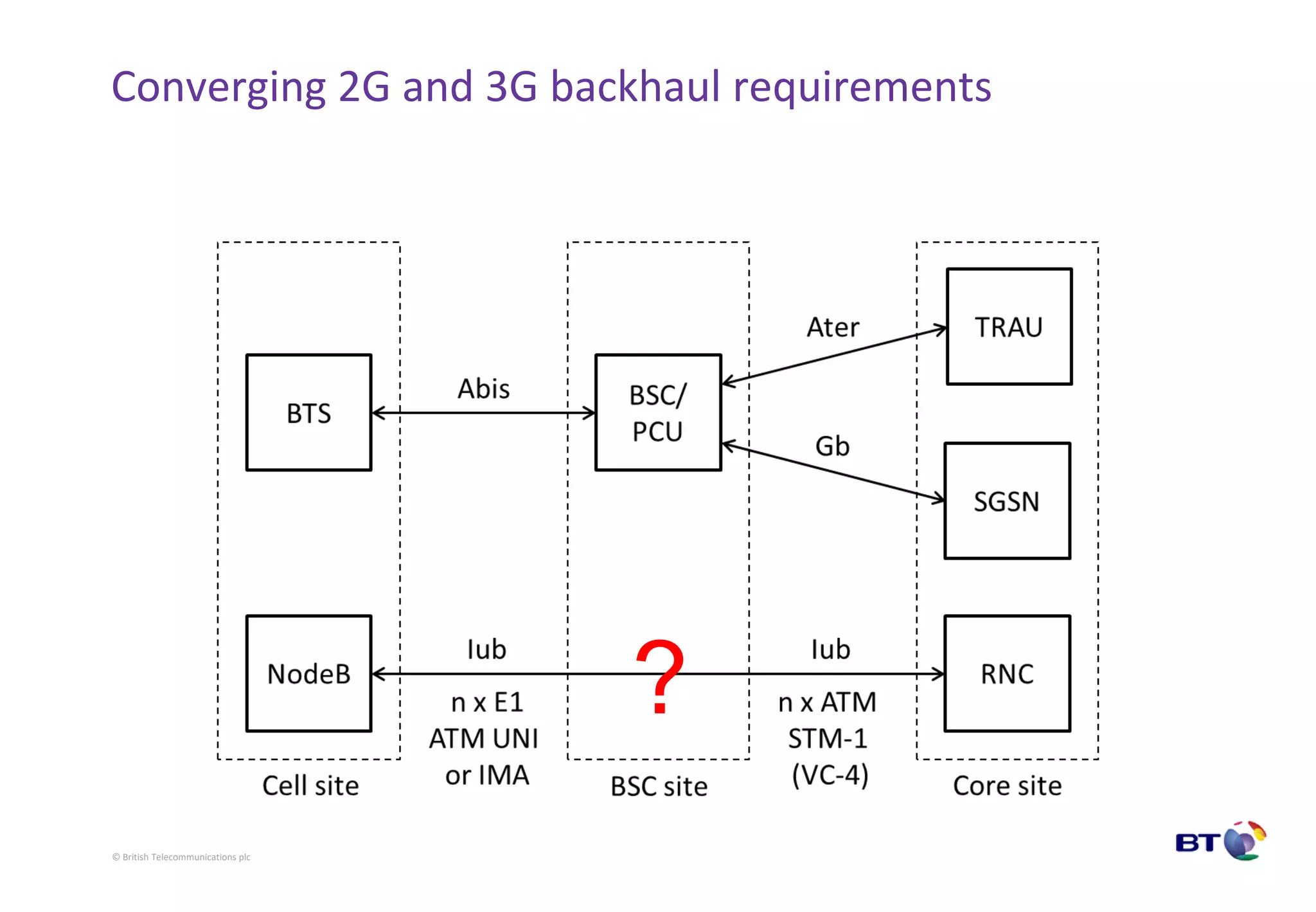
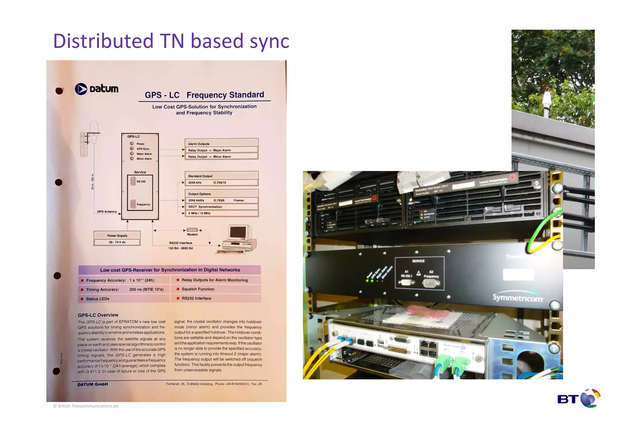
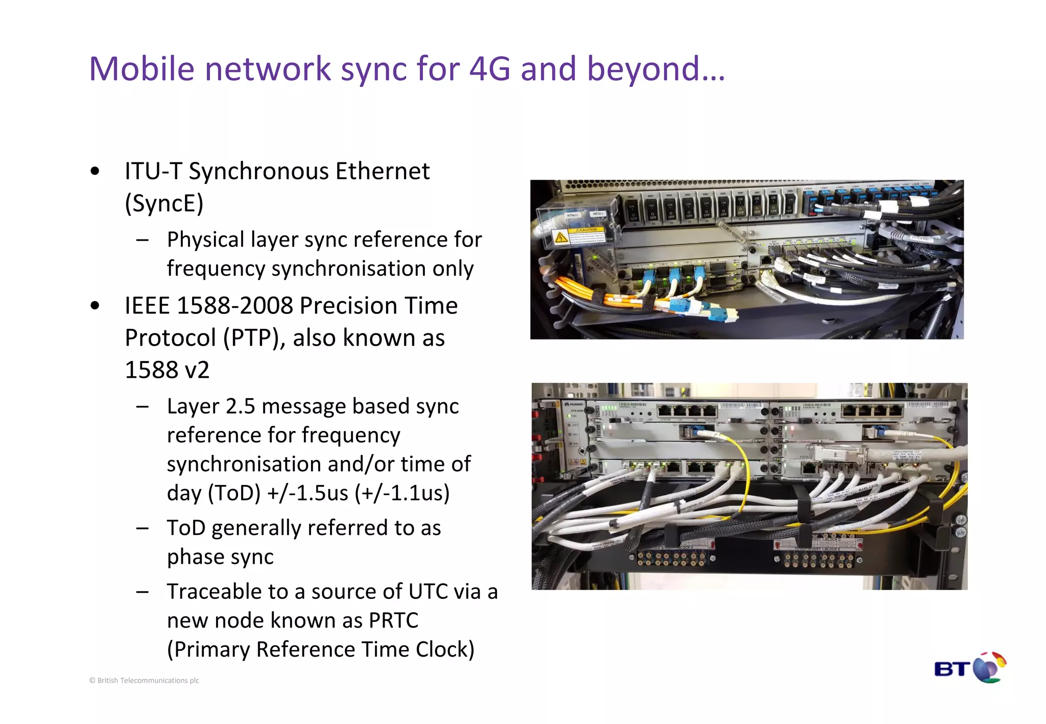


The document outlines the evolution of synchronization methods in digital cellular networks, emphasizing the importance of frequency and phase synchronization across generations from GSM to 5G. It discusses technological advancements such as pulse code modulation (PCM) and the transition from manual tuning of oscillators to automated synchronization solutions. Key modern synchronization technologies like Synchronous Ethernet and the Precision Time Protocol (PTP) are highlighted as essential for the operation of future mobile networks.


![Coded Agents – with UiPath SDK + LangGraph [Virtual Hands-on Workshop]](https://cdn.slidesharecdn.com/ss_thumbnails/codedagentsdeck-251215155422-5497c599-thumbnail.jpg?width=640&height=640&fit=bounds)


