Stepping up to the Challenge on Tighter Time Accuracy.
•
1 like•894 views

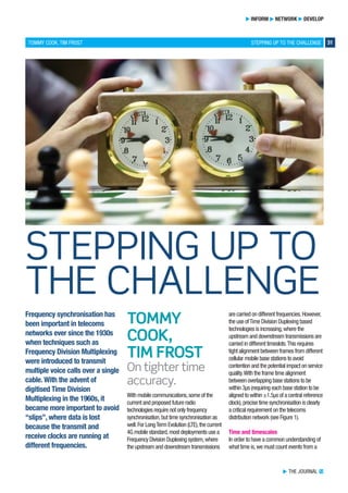
By Tommy Cook & Tim Frost Frequency synchronisation has been important in telecoms networks ever since the 1930s when techniques such as Frequency Division Multiplexing were introduced to transmit multiple voice calls over a single cable. With the advent of digitised Time Division Multiplexing in the 1960s, it became more important to avoid “slips”, where data is lost because the transmit and receive clocks are running at different frequencies. *** Shared with Permission from ITP Journal Volume 10 | Part 1 - 2016 ***

Recommended
More Related Content
What's hot
What's hot (20)
Similar to Stepping up to the Challenge on Tighter Time Accuracy.
Similar to Stepping up to the Challenge on Tighter Time Accuracy. (20)
More from 3G4G
More from 3G4G (20)
Recently uploaded
Recently uploaded (20)
Stepping up to the Challenge on Tighter Time Accuracy.
- 1. TOMMY COOK, TIM FROST STEPPING UP TO THE CHALLENGE 31 INFORM NETWORK DEVELOP Frequency synchronisation has been important in telecoms networks ever since the 1930s when techniques such as Frequency Division Multiplexing were introduced to transmit multiple voice calls over a single cable. With the advent of digitised Time Division Multiplexing in the 1960s, it became more important to avoid “slips”, where data is lost because the transmit and receive clocks are running at different frequencies. THE JOURNAL TJ With mobile communications,some of the current and proposed future radio technologies require not only frequency synchronisation,but time synchronisation as well.For LongTerm Evolution (LTE),the current 4G mobile standard,most deployments use a Frequency Division Duplexing system,where the upstream and downstream transmissions are carried on different frequencies.However, the use ofTime Division Duplexing based technologies is increasing,where the upstream and downstream transmissions are carried in different timeslots.This requires tight alignment between frames from different cellular mobile base stations to avoid contention and the potential impact on service quality.With the frame time alignment between overlapping base stations to be within 3µs (requiring each base station to be aligned to within ±1.5µs of a central reference clock),precise time synchronisation is clearly a critical requirement on the telecoms distribution network (see Figure 1). Time and timescales In order to have a common understanding of what time is,we must count events from a TOMMY COOK, TIM FROST On tighter time accuracy. STEPPING UP TO THE CHALLENGE
- 2. THE JOURNAL TJ 32 TOMMY COOK, TIM FROST common starting point,or‘epoch’.A timescale is the combination of a known frequency and a known epoch.The atomic second now provides the known,stable frequency for the timescales in use today.The current legal and civil timescale used by most countries is Coordinated UniversalTime (UTC),which is based on the frequency provided by the atomic second and the epoch of the Gregorian calendar. Having a common, known timescale provides a framework for ordering events occurring at different places. In the case of mobile telecoms, these events might be the start of a transmission frame at two or more base stations. With a common time reference, these frames can be co- ordinated such that they don’t overlap, causing transmission errors. Time Error – Time Error is a measure of the difference between the time reported by a local clock and that indicated by a reference clock. It is defined as the time at the measured clock, minus the time at the reference clock.Therefore it is only ever relative; Time Error has no meaning without a comparison to a reference. Time Error may vary, and can be expressed as a function of time. For example, if the rate of a clock is wrong, the Time Error will gradually increase over time, as demonstrated by a watch that needs adjusting every few days as it gets progressively more inaccurate. ITU-T Recommendation G.8260-Amd2 definesTime Error as having two primary components,namely,constantTime Error (cTE) and dynamicTime Error (dTE). cTE can be considered as the fixed error (i.e.constant offset),whereas dTE is the noise or variation in the instantaneous measure ofTime Error. Time Distribution With frequency,it is possible to have a standalone primary reference clock since Caesium clocks are known to be stable and accurate to within a given tolerance. However,there is no such thing as a standalone time reference. This is because of the relative nature of time; it must always be compared back to a known,common standard. Global Navigation Satellite Systems (GNSS) time distribution – The most accurate,publically available time messages today are transmitted by the various GNSSs such as Global Positioning System (GPS), GLObal NAvigation Satellite System or Beidou.These are referenced to UTC,or more precisely,the operator’s version of UTC. Therefore a typical Primary ReferenceTime Clock consists of a GNSS receiver plus a local oscillator used to maintain a local version of the timescale. The North American mobile systems, cdmaOne and cdma2000, use GPS at every base station for their primary source of time. GPS could also be adopted with LTE Time Division Duplexing and LTE Advanced, but there are several disadvantages: • It is a very low-power radio signal and requires a clear view of the sky for accurate time reception. • Indoor reception may not be possible due to attenuation through walls and roofs,and the expense of running and leasing cable space to the roof in a city may be prohibitive. • In urban locations,GPS suffers from multipath reflections from walls and buildings,reducing the accuracy of the received time. • The signal can be easily jammed,either accidentally or intentionally. • GPS is under control of the US Government,GLObal NAvigation Satellite System the Russian Government,Beidou the Chinese government,etc.Reliance on specific systems may be an issue politically in many countries in the world. Network time distribution – An alternative to GNSS is to use a packet protocol,such as NetworkTime Protocol or PrecisionTime Protocol (PTP) described in IEEE1588.Both of these work by sending a message containing the correct time through the network.In order to establish the message delay,so that the recipient can set their clock correctly,a return message is sent allowing the“round trip time”to be measured. Provided the original and returned message have the same delay, the one-way message delay can then be estimated as half the round trip time. If the two messages have different delays, then the estimate of the forward delay will be wrong by half the difference between the two delays. This is known as an‘asymmetry error’ and results in a cTE inaccuracy.This is a key source of error in time distribution because it cannot be detected by two-way exchange protocols.Asymmetry can arise for several different reasons: • Node asymmetry – The delay through each network node (e.g.switch or router) may not be equal in each direction. • Link asymmetry – The delay through the links between nodes may not be equal. This could be caused by (long) fibres or cables of different lengths,or by operating at different wavelengths over the same fibre. • Route asymmetry – Packet routing protocols do not guarantee that the packets will take the same route in each direction. dTE is caused by each packet taking a Volume 10 | Part 1 - 2016 Figure 1: Centralised time distribution to base stations.
- 3. STEPPING UP TO THE CHALLENGE 33 INFORM NETWORK DEVELOP different length of time to travel through the network.This is known as packet delay variation (PDV).The principal cause of PDV is queuing in each switch or router on the path, for example,while waiting for other packets to be transmitted.Queuing can be reduced by setting timing packets to the highest priority, but can’t be eliminated. Mitigation of Time Error – Packet protocols for time distribution include a number of ways to reduceTime Error.The NetworkTime Protocol describes an algorithm for filtering the timestamp values to reduce the impact of the PDV on the dTE1 . PTP doesn’t describe an algorithm – this is left up to the implementer.It does,however, describe two different methods of reducing the impact of PDV,both of which involve modifying the switches or routers on the path between the master device and the slave device: • Boundary Clocks (BCs) –This terminates the PTP flow at each BC-capable switch or router,synchronising its local clock to the PTP master.The device then re-generates the PTP messages to send to downstream devices. • Transparent Clocks (TCs) – This measures the time taken by the packet to pass through a switch or router,and adds this time to a correction field in the packet. The slave device then has a record of the delay for eachTC-capable switch or router in the path. The ITU-T has defined two“profiles”for the distribution of time across the network using PTP. The first is for the case where every node in the path between the master and the slave contains a BC.This is termed“full timing support”.The second is where there may be a mixture of ordinary switches and routers,and“PTP aware”devices (containing a BC orTC).This is known as“partial timing support”(see Figure 2). Time Error budgeting in networks ITU-T G.8271.1 defines a reference model for the deployment of PTP to a mobile base station or other similar application requiring precise time.For mobile base stations requiring better than 1.5µs accuracy,an example budget for the network is shown in Figure 3.This breaks the budget down into the cTE and dTE contributions for each part of the network based on the use of full timing support. One key point to note is that the budget for cTE is considerably larger than that for dTE. Of the 1.1µs allocated to the network (measured at the input to the base station), 800ns is for cTE,200ns for dTE,with the last 100ns (for the Primary ReferenceTime Clock) undefined.This is because with 10 nodes, cTE builds up rapidly,even with relatively small budgets allocated for equipment or links.Additionally,cTE is not filtered out by the clocks along the path,therefore it increases linearly through the network and grows very quickly as the number of nodes and links increase. This is not true for dTE,which if uncorrelated (noise-like),builds logarithmically. Centralised versus edge timing – Operators have taken two distinct approaches to network-based timing.The first is to use a mainly centralised model, with long chains of BCs connecting a central time reference to each base station.This centralised model requires very few Grandmaster (GM) clocks, but has a high potential for asymmetry error. In THE JOURNAL TJ 1 RFC5905,Section 10 (IETF,published June 2010). Figure 2: Full and PartialTiming Support. Figure 3: G.8271.1Time Error budget.
- 4. THE JOURNAL TJ 34 TOMMY COOK, TIM FROST some cases, where the links are extremely long (> 100km), operators have measured the asymmetry in a single fibre link at over 100ns. An alternative is to use so-called‘edge masters’,where the GM is moved as close as possible to the base stations.This has the advantage of reducing the number of nodes between the GM and the base stations,and the length of the fibres connecting those nodes. Both of these contribute to reducing the potential asymmetry. The disadvantage is that the number of GMs required is much higher,leading to higher operational complexity. Evaluating performance of network equipment –The approach above provides a building-block methodology that can be used in any full timing support network design.It shows how the performance required by the end application can be sub-divided and assigned to the various network components. This allows the network designer to use the specified performance of each BC,along with the known topology characteristics of their network,to determine suitable architectures to support the end application. Furthermore,the network budget can be broken down into a performance specification for each of the network elements in the chain.ITU-T G.8273.2 provides a specification for equipment (Boundary and Slave Clocks),that are suitable for use in full timing support networks.The elements of the clock specifications include the following parameters: • Noise generation – The intrinsic noise generated by the clock itself.This is typically measured by applying an‘ideal’, noise-free reference at the input,and comparing this reference to the output. • Noise tolerance –The maximum amount of noise the clock can tolerate at its input. • Noise transfer – How much noise at the input is filtered out by the clock.It is usually defined as the clock bandwidth. • Short-term transient response – The phase error generated during a switchover from one input reference to another (for example,in the event of a reference failure). • Long term transient response or holdover – The performance of the clock in the event of a total loss of input reference. Should a clock comply with Recommendation G.8273.2,it can be used in the G.8271.1 reference model with confidence that the end result will be sufficiently accurate. Testing performance of networks post deployment – Once equipment has been selected and a robust network architecture deduced,there are multiple stages of assessing actual network performance. Installation usually involves minimal testing, primarily aimed at checking that there are no equipment failures. A number of go/no-go tests will be performed to ensure all the equipment is operating correctly before the new installation goes live. The subject of‘how much post-deployment monitoring is necessary’ is one that is leading to alternative approaches.The conceptual approach taken by most networks today typically implements failure detection only. Each piece of equipment in the network has fault monitoring capability to inform the operations,administration and maintenance system if there has been an equipment or network failure. This monitoring primarily focuses on hard faults where links and/or equipment are no longer operating.However,there is debate in the industry regarding the need for quality monitoring that provides additional fault indications where,for example,all the links are working but the quality of the delivered ‘time’ is failing to meet network requirements.This approach would necessitate the addition of monitor probes through the network to provide an indication of performance with respect to network limits.These probes could also provide an early warning of impending failure and/or highlight where the mobile network is not achieving acceptable performance. Once a fault is reported in the network,the initial course of action is likely to involve swapping out equipment to get the system up and running again. If this fails to resolve the issue,it is often necessary to use sophisticated test equipment that can record detailed performance at the location of the fault (see Figure 4). A primary challenge with performing accurate time measurements in the field is access to the reference.As stated earlier, time is always measured with respect to a reference.If it is possible to use a GNSS antenna at the fault location,then this will provide a suitable reference.At many sites, though,this can be problematic as the equipment under test could be,for example, Volume 10 | Part 1 - 2016 Figure 4:Testing performance in the field.
- 5. STEPPING UP TO THE CHALLENGE 35 INFORM NETWORK DEVELOP in the basement of a building or somewhere where sight to the sky is not possible. A simple solution would be to use test equipment with a built-in rubidium reference. The rubidium can be trained to GNSS beforehand so that when the test equipment is taken to the fault location,it can be used to monitor network performance without the need for a permanent GNSS connection. Delivering time with NFV technologies There is significant momentum building in evolving the whole network to utilising Network FunctionVirtualisation (NFV) of switches and routers in standardised servers rather than supplier-specific hardware platforms.The deployment of this technology is at an early stage and while unlikely to deliver time synchronisation to the accuracy required by today’s base stations,the migration looks highly likely at some point in the future. As such,it will be necessary to solve the problem of delivering time synchronisation throughout an NFV network. NFV networks need to measure time for a range of applications albeit less accurately than that required for base stations.Today, the focus is on areas such as throughput, orchestration and security,but far less attention has been given to synchronisation and timing. The ETSI NFV Industry Specification Group has stated that IEEE 1588 (PTP) will be used with implementations in physical Network Interface Controllers to provide precise timestamps to virtual functions – but the problem of transferring such timestamps from the physical to the virtual world is fraught with difficulty. The problems come down to the usual ones in time synchronisation – determining and allowing for delays and asymmetry to a suitable degree of resolution and accuracy. The challenges associated with these issues in the NFV world are severe unless special measures are taken to reduce the time uncertainty inherent in running‘regular’ software functions.For various reasons,the timing of software execution in modern computer systems is several orders of magnitude less deterministic than hardware. It is also several orders of magnitude less granular,that is,has lower resolution. Evidently there are a number of steps to take and problems to solve before network elements that require synchronisation can be fully virtualised.The first requirement is to bind the problem by enforcing some constraints.For example: 1.Standardise hardware that allows for more deterministic software – chipset manufacturers like Intel and others are already doing work in this area.This may include hardware implemented timestamping. 2.Develop and standardise software languages,compilers and other infrastructure aimed specifically at timing problems. 3.Develop truly real-time operating systems that,when combined with the above,will allow“correct by construction”designs that can be simulated and their timing accuracy verified. AUTHORS’ CONCLUSIONS Delivering accurate time through the network is a crucial part of today’s telecom infrastructure,and looks likely to continue to be so,with new technologies needing equal or better quality time.Delivering accurate time through a network is a challenge and requires careful consideration and design to ensure the stringent requirements of base stations are met.Moreover,the problem will get more difficult with new technologies demanding even tighter time accuracy. Standards are in place defining performance and providing guidance on how to build networks to deliver accurate time.Test methodologies and test equipment are available to prove conformance to these standards.And today,there are deployments that contribute to our understanding of what is achievable to crystallise.This knowledge will be essential to enable the development of future networks to deliver even tighter time accuracy to support the insatiable appetite for more capacity delivered by the mobile network. THE JOURNAL TJ ITPINSIGHT CALL Want to talk to the authors? To discuss this article and its content, join in the ITP Insight Call on 15 July. To book onto the call visit: https://www.theitp.org/calendar/ ABBREVIATIONS BC Boundary Clock cTE constantTime Error dTE dynamicTime Error GM Grandmaster GNSS Global Navigation Satellite System GPS Global Positioning System LTE LongTerm Evolution PDV Packet DelayVariation PTP PrecisionTime Protocol TC Transparent Clock UTC Coordinated UniversalTime ABOUT THE AUTHORS Tommy Cook Tommy is the Founder and CEO of Calnex Solutions,a leading provider of test solutions for telecom synchronisation technologies.He has over 33 years’ experience in telecoms test and measurement,including experience with leading Blue Chip companies in the sector prior to founding Calnex and guiding the company to a globally recognised leader in precision time measurement. Tim Frost Tim is a specialist in next- generation synchronisation techniques,having worked with Zarlink Semiconductor, Symmetricom and now Calnex Solutions on packet-based synchronisation technologies. He is an active contributor to the ITU-T,and has also contributed to the Small Cell Forum, Metro Ethernet Forum and IETF. Tim has over 30 years’ experience in the electronics and telecommunications industry,and is a Member of the IET and a Chartered Engineer.