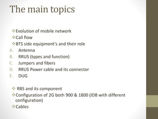
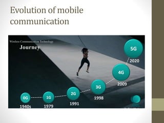
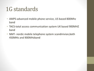
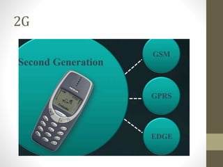
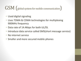
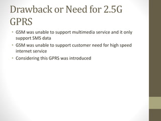
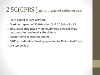
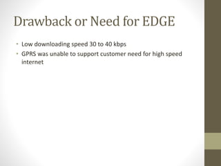
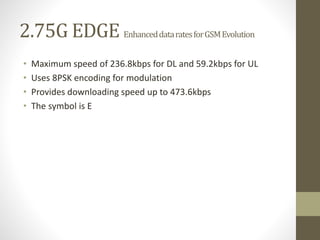
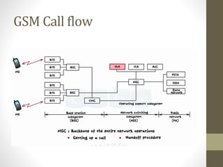
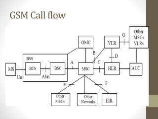
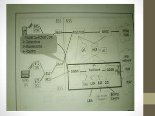
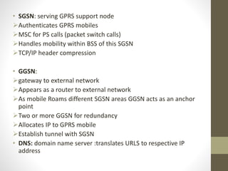
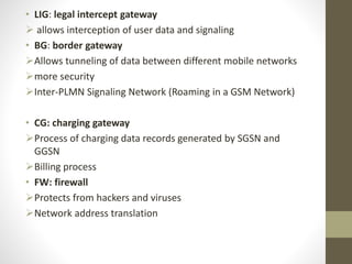
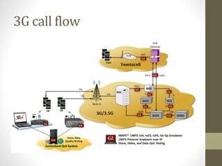
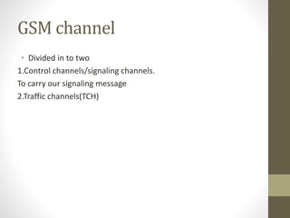
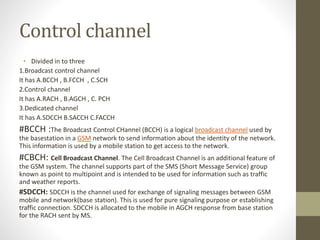
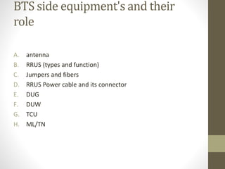
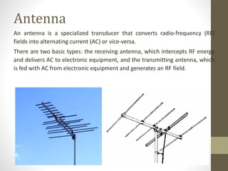
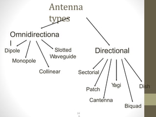
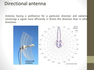
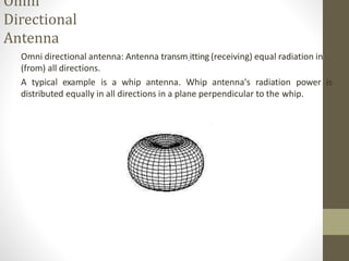
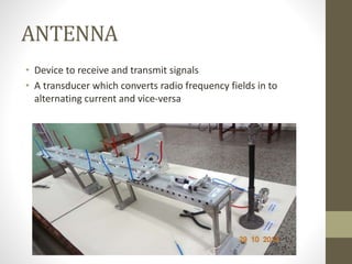
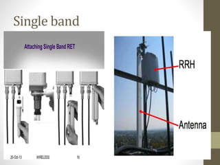
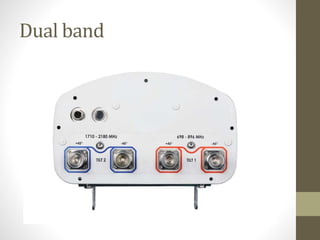
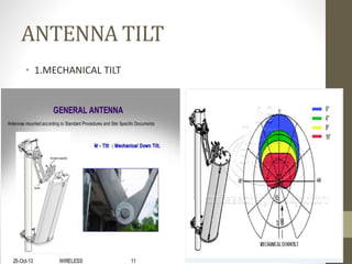
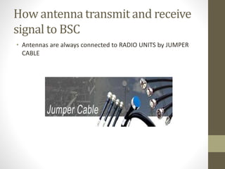
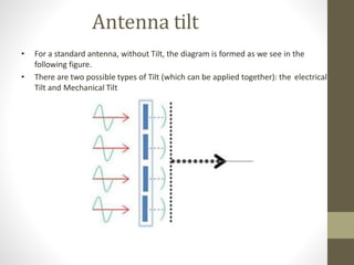
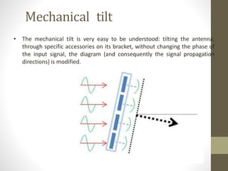
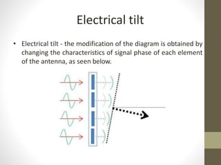
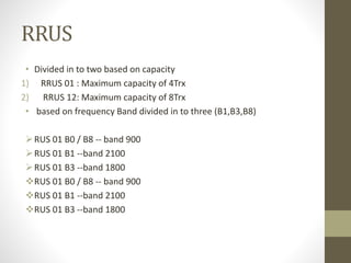
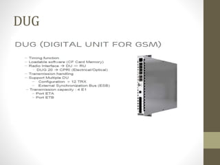
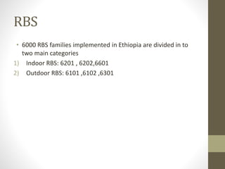
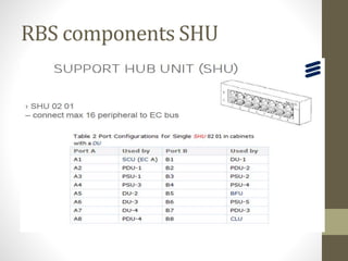
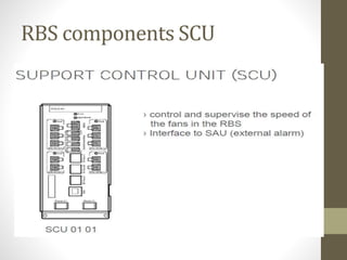
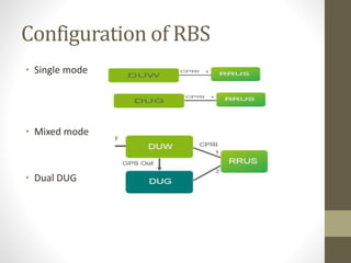
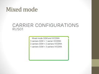
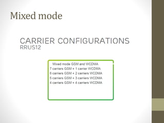
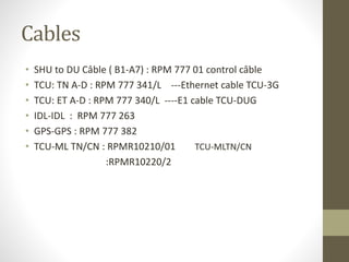
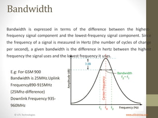
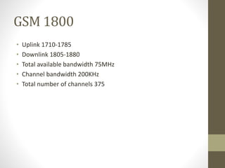
Telecomfundamentals 2G
Prepared by wegene bogale
The main topics
Evolution of mobile network
Call flow
BTS side equipment's and their role
A. Antenna
B. RRUS (types and function)
C. Jumpers and fibers
D. RRUS Power cable and its connector
E. DUG
 RBS and its component
Configuration of 2G both 900 & 1800 (IDB with different
configuration)
Cables
Evolution of mobile
communication
0G
• Used technologies like
Push to talk mobile (PTT or manual)
Mobile telephone service(MTS)
 Too heavy to carry by people so usually mounted on the car , antennas
(senders and receivers ) on the back of the car and the phone on the front
1G
• Uses analog signaling so it easily altered by external sources, so it provides poor
voice quality
• Uses FDMA multiplexing
• Only voice call
• Maximum speed of 2.4kbps
• Poor battery life and voice quality
• Data transmissions at 150MHz
• Big size mobile phone
1G standards
• AMPS-advanced mobile phone service, US based 800Mhz
band
• TACS-total access communication system UK based 900MHZ
band
• NMT- nordic mobile telephone system scandinivian,both
450MHz and 900MHzband
Drawback of 1G
Wireless transmission is in analog format (sinusodial) ,this
signals can easily be altered by external sources ,so it provides
poor voice quality and poor security
Uses FDMA uses available spectrum in inefficient way
2G
GSM (globalsystemformobilecommunication)
• Used digital signaling
• Uses TDMA & CDMA technologies for multiplexing
900MHz frequency
• Data rate of 14.4kbps for both UL/DL
• Introduce data service called SMS(short message service)
• No internet service
• Smaller and more secured mobile phones
Drawback or Need for 2.5G
GPRS
• GSM was unable to support multimedia service and it only
support SMS data
• GSM was unable to support customer need for high speed
internet service
• Considering this GPRS was introduced
2.5G(GPRS ) generalpacketradioservice
o pure packet service network
o Maximum speed of 53.6kbps for DL & 26.8kbps for UL
o This speed introduced MMS(multimedia service) allow
customers to send media like pictures
o Support IP to connect to internet
o GPRS provides downloading speed up to 30kbps to 40kbps
o the symbol is G
Drawback or Need for EDGE
• Low downloading speed 30 to 40 kbps
• GPRS was unable to support customer need for high speed
internet
2.75G EDGE EnhanceddataratesforGSMEvolution
• Maximum speed of 236.8kbps for DL and 59.2kbps for UL
• Uses 8PSK encoding for modulation
• Provides downloading speed up to 473.6kbps
• The symbol is E
GSM Call flow
GSM Call flow
• SGSN: serving GPRS support node
Authenticates GPRS mobiles
MSC for PS calls (packet switch calls)
Handles mobility within BSS of this SGSN
TCP/IP header compression
• GGSN:
gateway to external network
Appears as a router to external network
As mobile Roams different SGSN areas GGSN acts as an anchor
point
Two or more GGSN for redundancy
Allocates IP to GPRS mobile
Establish tunnel with SGSN
• DNS: domain name server :translates URLS to respective IP
address
• LIG: legal intercept gateway
 allows interception of user data and signaling
• BG: border gateway
Allows tunneling of data between different mobile networks
more security
Inter-PLMN Signaling Network (Roaming in a GSM Network)
• CG: charging gateway
Process of charging data records generated by SGSN and
GGSN
Billing process
• FW: firewall
Protects from hackers and viruses
Network address translation
3G call flow
GSM channel
• Divided in to two
1.Control channels/signaling channels.
To carry our signaling message
2.Traffic channels(TCH)
Control channel
• Divided in to three
1.Broadcast control channel
It has A.BCCH , B.FCCH , C.SCH
2.Control channel
It has A.RACH , B.AGCH , C. PCH
3.Dedicated channel
It has A.SDCCH B.SACCH C.FACCH
#BCCH :The Broadcast Control CHannel (BCCH) is a logical broadcast channel used by
the basestation in a GSM network to send information about the identity of the network.
This information is used by a mobile station to get access to the network.
#CBCH: Cell Broadcast Channel. The Cell Broadcast Channel is an additional feature of
the GSM system. The channel supports part of the SMS (Short Message Service) group
known as point to multipoint and is intended to be used for information such as traffic
and weather reports.
#SDCCH: SDCCH is the channel used for exchange of signaling messages between GSM
mobile and network(base station). This is used for pure signaling purpose or establishing
traffic connection. SDCCH is allocated to the mobile in AGCH response from base station
for the RACH sent by MS.
BTS side equipment's and their
role
A. antenna
B. RRUS (types and function)
C. Jumpers and fibers
D. RRUS Power cable and its connector
E. DUG
F. DUW
G. TCU
H. ML/TN
Antenna
An antenna is a specialized transducer that converts radio-frequency (RF)
fields into alternating current (AC) or vice-versa.
There are two basic types: the receiving antenna, which intercepts RF energy
and delivers AC to electronic equipment, and the transmitting antenna, which
is fed with AC from electronic equipment and generates an RF field.
Antenna
types
Omnidirectiona
l
Dipole
Monopole
Slotted
Waveguide
Collinear
Directional
Sectorial
Dish
Patch
Cantenna
Biquad
Y
agi
14
Directional antenna
Antenna having a preference for a particular direction and radiating
(receiving) a signal more efficiently in (from) this direction than in other
directions.
Omni
Directional
Antenna
Omni directional antenna: Antenna transm.itting (receiving) equal radiation in
(from) all directions.
A typical example is a whip antenna. Whip antenna's radiation power is
distributed equally in all directions in a plane perpendicular to the whip.
ANTENNA
• Device to receive and transmit signals
• A transducer which converts radio frequency fields in to
alternating current and vice-versa
ANTENNA
• Grouped under directional antenna
• There are deferent kinds of antenna
1.single band
2.dual band
3.tripple band
• 2L 4H
• 2L 5H
Single band
Dual band
Triple band antennas
ANTENNA TILT
• 1.MECHANICAL TILT
ANTENNA TILT
• 2.ELECTRICAL TILT; its changing the characteristics of the
signal phase
How antenna transmit and receive
signal to BSC
• Antennas are always connected to RADIO UNITS by JUMPER
CABLE
Antenna tilt
• For a standard antenna, without Tilt, the diagram is formed as we see in the
following figure.
• There are two possible types of Tilt (which can be applied together): the electrical
Tilt and Mechanical Tilt
Mechanical tilt
• The mechanical tilt is very easy to be understood: tilting the antenna,
through specific accessories on its bracket, without changing the phase of
the input signal, the diagram (and consequently the signal propagation
directions) is modified.
Electrical tilt
• Electrical tilt - the modification of the diagram is obtained by
changing the characteristics of signal phase of each element
of the antenna, as seen below.
RRUS
• Divided in to two based on capacity
1) RRUS 01 : Maximum capacity of 4Trx
2) RRUS 12: Maximum capacity of 8Trx
• based on frequency Band divided in to three (B1,B3,B8)
RUS 01 B0 / B8 -- band 900
RUS 01 B1 --band 2100
RUS 01 B3 --band 1800
RUS 01 B0 / B8 -- band 900
RUS 01 B1 --band 2100
RUS 01 B3 --band 1800
DUG
RBS and its component
RBS
• 6000 RBS families implemented in Ethiopia are divided in to
two main categories
1) Indoor RBS: 6201 , 6202,6601
2) Outdoor RBS: 6101 ,6102 ,6301
RBS components SHU
RBS components SCU
RBS components SAU
Configuration of RBS
• Single mode
• Mixed mode
• Dual DUG
Mixed mode
Mixed mode
Cables
• SHU to DU Câble ( B1-A7) : RPM 777 01 control câble
• TCU: TN A-D : RPM 777 341/L ---Ethernet cable TCU-3G
• TCU: ET A-D : RPM 777 340/L ----E1 cable TCU-DUG
• IDL-IDL : RPM 777 263
• GPS-GPS : RPM 777 382
• TCU-ML TN/CN : RPMR10210/01 TCU-MLTN/CN
:RPMR10220/2
Configuration using OMT
Software
• Describe using OMT
• Master and slave DUG
• G444 D444
• G222 d444
• G555 D444
• G666 D444
• G888 D666
• G444 D888
• Sharing two RRUS 01 for getting 8Trx
• PSI
DU-TCU-ML Cable diagram
• Refer the diagram
© UTL Technologies www.utltraining.com
Bandwidth
Bandwidth is expressed in terms of the difference between the highest-
frequency signal component and the lowest-frequency signal component. Since
the frequency of a signal is measured in Hertz (the number of cycles of change
per second), a given bandwidth is the difference in hertz between the highest
frequency the signal uses and the lowest frequency it uses.
E.g: For GSM 900
Bandwidth is 25MHz.Uplink
Frequency890-915MHz
(25Mhz-difference)
Downlink Frequency 935-
960MHz
GSM 900
• Up link 890-915
• Downlink 935-960
• Total available band width 25MHz
• Channel bandwidth 200kHz
• Total number of channels 125
• ARFCN –absoulute radio frequency channel number used to
express one pair of RF channels
ARFCN=Fup-890/.2 or fdown-935/.2
GSM 1800
• Uplink 1710-1785
• Downlink 1805-1880
• Total available bandwidth 75MHz
• Channel bandwidth 200KHz
• Total number of channels 375
E1
• What is E1?
• E1 consists of 32 channels, which can be used to carry simultaneous voice calls,
and each channel is called as a Time Slot (TS). As per the ITU-T
recommendations, 2 time slots are reserved for signaling and synchronization.
Therefore, E1 can carry 30 voice calls or data communications simultaneously.
Each Time Slot of E1 has a bandwidth of 64 Kbps, which leads to 2048 Kbps total
speed for an E1 carrier.
• Time division multiplexing is used to separate the channels from each other.
In general E1 time slots are designed to send Pulse Code Modulated (PCM) voice
signals, which have a sampling frequency of 8000 samples per second. Due to
this reason, each E1 frame is designed to send 1 sample from each channel and
the size of E1 frame is limited to 125 µs (1s/8000). So, within this 125µs frame
interval, 32 samples should be sent, which has 8 bits in each sample. Therefore,
the total number of bits that should be transferred in a single frame is 256 bits.
Two types of physical delivery methods are available as per the E1 standard,
which is called as balanced physical delivery and unbalanced physical delivery.
Balanced physical delivery is the most popular method, which uses 4 copper
wires grouped as two pairs for transmit and receive paths.
What is the difference between E1 and T1?
E1 and T1 are digital telecommunication carrier standards; in other
words, multi-channel telecommunication systems, which are time
multiplexed into a single carrier to transmit and receive. Both
standards use two pairs of wires for transmit and receive paths to
achieve full duplex communication. Initially, both methods are
developed in order to send voice channels over copper wires
simultaneously, which leads to less transmission cost.
– Data rate of E1 is 2048kbps as per the recommendations of ITU-T,
while the data rate of T1 is 1.544Mbps as per the ANSI
recommendations.
– E1 comprises of 32 simultaneous channels, while T1 consists of 24
simultaneous channels, which has 64kbps data rate in each channel.
– Since both systems initially designed to transmit PCM voice, frame
rate of both carriers are designed as 8000 frames per second to
support 8kHz sampling rate of PCM.
– Even though both E1 and T1 have same 125µS frame interval, E1
transmit 256 bits, while T1 transmit 193 bits within the same period.
– In general E1 uses European standard of PCM called A-law while T1
uses North American standard of PCM known as µ-Law as voice
channel modulation method.
contd
• – Even though both E1 and T1 have same 125µS frame
interval, E1 transmit 256 bits, while T1 transmit 193 bits
within the same period.
• – In general E1 uses European standard of PCM called A-law
while T1 uses North American standard of PCM known as µ-
Law as voice channel modulation method.
 – Both E1 and T1 carrier methods are initially developed to
transmit and receive pulse code modulated voice signals over
time multiplexed copper wires.
• – Key difference of E1 and T1 is the number of channels,
which can be transmitted simultaneously over the given
physical medium.
THANKS!!!

mobile network.pptx

  • 1.
  • 2.
    The main topics Evolutionof mobile network Call flow BTS side equipment's and their role A. Antenna B. RRUS (types and function) C. Jumpers and fibers D. RRUS Power cable and its connector E. DUG  RBS and its component Configuration of 2G both 900 & 1800 (IDB with different configuration) Cables
  • 3.
  • 4.
    0G • Used technologieslike Push to talk mobile (PTT or manual) Mobile telephone service(MTS)  Too heavy to carry by people so usually mounted on the car , antennas (senders and receivers ) on the back of the car and the phone on the front
  • 5.
    1G • Uses analogsignaling so it easily altered by external sources, so it provides poor voice quality • Uses FDMA multiplexing • Only voice call • Maximum speed of 2.4kbps • Poor battery life and voice quality • Data transmissions at 150MHz • Big size mobile phone
  • 6.
    1G standards • AMPS-advancedmobile phone service, US based 800Mhz band • TACS-total access communication system UK based 900MHZ band • NMT- nordic mobile telephone system scandinivian,both 450MHz and 900MHzband
  • 7.
    Drawback of 1G Wirelesstransmission is in analog format (sinusodial) ,this signals can easily be altered by external sources ,so it provides poor voice quality and poor security Uses FDMA uses available spectrum in inefficient way
  • 8.
  • 9.
    GSM (globalsystemformobilecommunication) • Useddigital signaling • Uses TDMA & CDMA technologies for multiplexing 900MHz frequency • Data rate of 14.4kbps for both UL/DL • Introduce data service called SMS(short message service) • No internet service • Smaller and more secured mobile phones
  • 10.
    Drawback or Needfor 2.5G GPRS • GSM was unable to support multimedia service and it only support SMS data • GSM was unable to support customer need for high speed internet service • Considering this GPRS was introduced
  • 11.
    2.5G(GPRS ) generalpacketradioservice opure packet service network o Maximum speed of 53.6kbps for DL & 26.8kbps for UL o This speed introduced MMS(multimedia service) allow customers to send media like pictures o Support IP to connect to internet o GPRS provides downloading speed up to 30kbps to 40kbps o the symbol is G
  • 12.
    Drawback or Needfor EDGE • Low downloading speed 30 to 40 kbps • GPRS was unable to support customer need for high speed internet
  • 13.
    2.75G EDGE EnhanceddataratesforGSMEvolution •Maximum speed of 236.8kbps for DL and 59.2kbps for UL • Uses 8PSK encoding for modulation • Provides downloading speed up to 473.6kbps • The symbol is E
  • 15.
  • 16.
  • 18.
    • SGSN: servingGPRS support node Authenticates GPRS mobiles MSC for PS calls (packet switch calls) Handles mobility within BSS of this SGSN TCP/IP header compression • GGSN: gateway to external network Appears as a router to external network As mobile Roams different SGSN areas GGSN acts as an anchor point Two or more GGSN for redundancy Allocates IP to GPRS mobile Establish tunnel with SGSN • DNS: domain name server :translates URLS to respective IP address
  • 19.
    • LIG: legalintercept gateway  allows interception of user data and signaling • BG: border gateway Allows tunneling of data between different mobile networks more security Inter-PLMN Signaling Network (Roaming in a GSM Network) • CG: charging gateway Process of charging data records generated by SGSN and GGSN Billing process • FW: firewall Protects from hackers and viruses Network address translation
  • 20.
  • 21.
    GSM channel • Dividedin to two 1.Control channels/signaling channels. To carry our signaling message 2.Traffic channels(TCH)
  • 22.
    Control channel • Dividedin to three 1.Broadcast control channel It has A.BCCH , B.FCCH , C.SCH 2.Control channel It has A.RACH , B.AGCH , C. PCH 3.Dedicated channel It has A.SDCCH B.SACCH C.FACCH #BCCH :The Broadcast Control CHannel (BCCH) is a logical broadcast channel used by the basestation in a GSM network to send information about the identity of the network. This information is used by a mobile station to get access to the network. #CBCH: Cell Broadcast Channel. The Cell Broadcast Channel is an additional feature of the GSM system. The channel supports part of the SMS (Short Message Service) group known as point to multipoint and is intended to be used for information such as traffic and weather reports. #SDCCH: SDCCH is the channel used for exchange of signaling messages between GSM mobile and network(base station). This is used for pure signaling purpose or establishing traffic connection. SDCCH is allocated to the mobile in AGCH response from base station for the RACH sent by MS.
  • 23.
    BTS side equipment'sand their role A. antenna B. RRUS (types and function) C. Jumpers and fibers D. RRUS Power cable and its connector E. DUG F. DUW G. TCU H. ML/TN
  • 24.
    Antenna An antenna isa specialized transducer that converts radio-frequency (RF) fields into alternating current (AC) or vice-versa. There are two basic types: the receiving antenna, which intercepts RF energy and delivers AC to electronic equipment, and the transmitting antenna, which is fed with AC from electronic equipment and generates an RF field.
  • 25.
  • 26.
    Directional antenna Antenna havinga preference for a particular direction and radiating (receiving) a signal more efficiently in (from) this direction than in other directions.
  • 27.
    Omni Directional Antenna Omni directional antenna:Antenna transm.itting (receiving) equal radiation in (from) all directions. A typical example is a whip antenna. Whip antenna's radiation power is distributed equally in all directions in a plane perpendicular to the whip.
  • 28.
    ANTENNA • Device toreceive and transmit signals • A transducer which converts radio frequency fields in to alternating current and vice-versa
  • 29.
    ANTENNA • Grouped underdirectional antenna • There are deferent kinds of antenna 1.single band 2.dual band 3.tripple band • 2L 4H • 2L 5H
  • 30.
  • 31.
  • 32.
  • 33.
  • 34.
    ANTENNA TILT • 2.ELECTRICALTILT; its changing the characteristics of the signal phase
  • 35.
    How antenna transmitand receive signal to BSC • Antennas are always connected to RADIO UNITS by JUMPER CABLE
  • 36.
    Antenna tilt • Fora standard antenna, without Tilt, the diagram is formed as we see in the following figure. • There are two possible types of Tilt (which can be applied together): the electrical Tilt and Mechanical Tilt
  • 37.
    Mechanical tilt • Themechanical tilt is very easy to be understood: tilting the antenna, through specific accessories on its bracket, without changing the phase of the input signal, the diagram (and consequently the signal propagation directions) is modified.
  • 38.
    Electrical tilt • Electricaltilt - the modification of the diagram is obtained by changing the characteristics of signal phase of each element of the antenna, as seen below.
  • 39.
    RRUS • Divided into two based on capacity 1) RRUS 01 : Maximum capacity of 4Trx 2) RRUS 12: Maximum capacity of 8Trx • based on frequency Band divided in to three (B1,B3,B8) RUS 01 B0 / B8 -- band 900 RUS 01 B1 --band 2100 RUS 01 B3 --band 1800 RUS 01 B0 / B8 -- band 900 RUS 01 B1 --band 2100 RUS 01 B3 --band 1800
  • 40.
  • 41.
    RBS and itscomponent
  • 42.
    RBS • 6000 RBSfamilies implemented in Ethiopia are divided in to two main categories 1) Indoor RBS: 6201 , 6202,6601 2) Outdoor RBS: 6101 ,6102 ,6301
  • 43.
  • 44.
  • 45.
  • 46.
    Configuration of RBS •Single mode • Mixed mode • Dual DUG
  • 47.
  • 48.
  • 49.
    Cables • SHU toDU Câble ( B1-A7) : RPM 777 01 control câble • TCU: TN A-D : RPM 777 341/L ---Ethernet cable TCU-3G • TCU: ET A-D : RPM 777 340/L ----E1 cable TCU-DUG • IDL-IDL : RPM 777 263 • GPS-GPS : RPM 777 382 • TCU-ML TN/CN : RPMR10210/01 TCU-MLTN/CN :RPMR10220/2
  • 50.
    Configuration using OMT Software •Describe using OMT • Master and slave DUG • G444 D444 • G222 d444 • G555 D444 • G666 D444 • G888 D666 • G444 D888 • Sharing two RRUS 01 for getting 8Trx • PSI
  • 51.
    DU-TCU-ML Cable diagram •Refer the diagram
  • 52.
    © UTL Technologieswww.utltraining.com Bandwidth Bandwidth is expressed in terms of the difference between the highest- frequency signal component and the lowest-frequency signal component. Since the frequency of a signal is measured in Hertz (the number of cycles of change per second), a given bandwidth is the difference in hertz between the highest frequency the signal uses and the lowest frequency it uses. E.g: For GSM 900 Bandwidth is 25MHz.Uplink Frequency890-915MHz (25Mhz-difference) Downlink Frequency 935- 960MHz
  • 53.
    GSM 900 • Uplink 890-915 • Downlink 935-960 • Total available band width 25MHz • Channel bandwidth 200kHz • Total number of channels 125 • ARFCN –absoulute radio frequency channel number used to express one pair of RF channels ARFCN=Fup-890/.2 or fdown-935/.2
  • 54.
    GSM 1800 • Uplink1710-1785 • Downlink 1805-1880 • Total available bandwidth 75MHz • Channel bandwidth 200KHz • Total number of channels 375
  • 55.
    E1 • What isE1? • E1 consists of 32 channels, which can be used to carry simultaneous voice calls, and each channel is called as a Time Slot (TS). As per the ITU-T recommendations, 2 time slots are reserved for signaling and synchronization. Therefore, E1 can carry 30 voice calls or data communications simultaneously. Each Time Slot of E1 has a bandwidth of 64 Kbps, which leads to 2048 Kbps total speed for an E1 carrier. • Time division multiplexing is used to separate the channels from each other. In general E1 time slots are designed to send Pulse Code Modulated (PCM) voice signals, which have a sampling frequency of 8000 samples per second. Due to this reason, each E1 frame is designed to send 1 sample from each channel and the size of E1 frame is limited to 125 µs (1s/8000). So, within this 125µs frame interval, 32 samples should be sent, which has 8 bits in each sample. Therefore, the total number of bits that should be transferred in a single frame is 256 bits. Two types of physical delivery methods are available as per the E1 standard, which is called as balanced physical delivery and unbalanced physical delivery. Balanced physical delivery is the most popular method, which uses 4 copper wires grouped as two pairs for transmit and receive paths.
  • 56.
    What is thedifference between E1 and T1? E1 and T1 are digital telecommunication carrier standards; in other words, multi-channel telecommunication systems, which are time multiplexed into a single carrier to transmit and receive. Both standards use two pairs of wires for transmit and receive paths to achieve full duplex communication. Initially, both methods are developed in order to send voice channels over copper wires simultaneously, which leads to less transmission cost. – Data rate of E1 is 2048kbps as per the recommendations of ITU-T, while the data rate of T1 is 1.544Mbps as per the ANSI recommendations. – E1 comprises of 32 simultaneous channels, while T1 consists of 24 simultaneous channels, which has 64kbps data rate in each channel. – Since both systems initially designed to transmit PCM voice, frame rate of both carriers are designed as 8000 frames per second to support 8kHz sampling rate of PCM. – Even though both E1 and T1 have same 125µS frame interval, E1 transmit 256 bits, while T1 transmit 193 bits within the same period. – In general E1 uses European standard of PCM called A-law while T1 uses North American standard of PCM known as µ-Law as voice channel modulation method.
  • 57.
    contd • – Eventhough both E1 and T1 have same 125µS frame interval, E1 transmit 256 bits, while T1 transmit 193 bits within the same period. • – In general E1 uses European standard of PCM called A-law while T1 uses North American standard of PCM known as µ- Law as voice channel modulation method.  – Both E1 and T1 carrier methods are initially developed to transmit and receive pulse code modulated voice signals over time multiplexed copper wires. • – Key difference of E1 and T1 is the number of channels, which can be transmitted simultaneously over the given physical medium.
  • 58.