Download as PDF, PPTX


The document discusses different aspects of engineering drawings including: 1. Common sizes for drawing paper include 8.5" x 11", 11" x 17", and 17" x 22". 2. Title blocks contain information about the drawing. 3. Scales are used to shrink or enlarge objects to fit on the drawing paper according to British standards. 4. There are vertical and sloping methods for drawing letters and numbers.
Introduction to Engineering Drawing, course identifier, and class number.
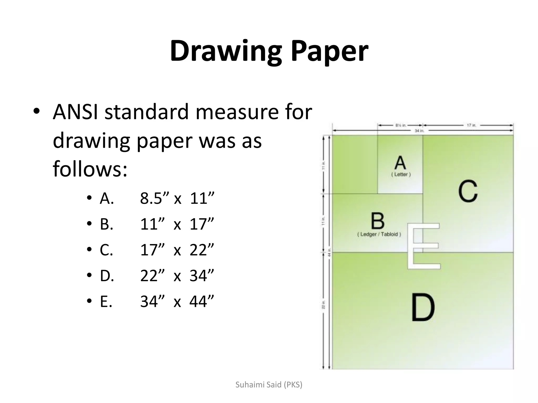
Standard sizes for drawing paper: A (8.5"x11"), B (11"x17"), C (17"x22"), D (22"x34"), E (34"x44").
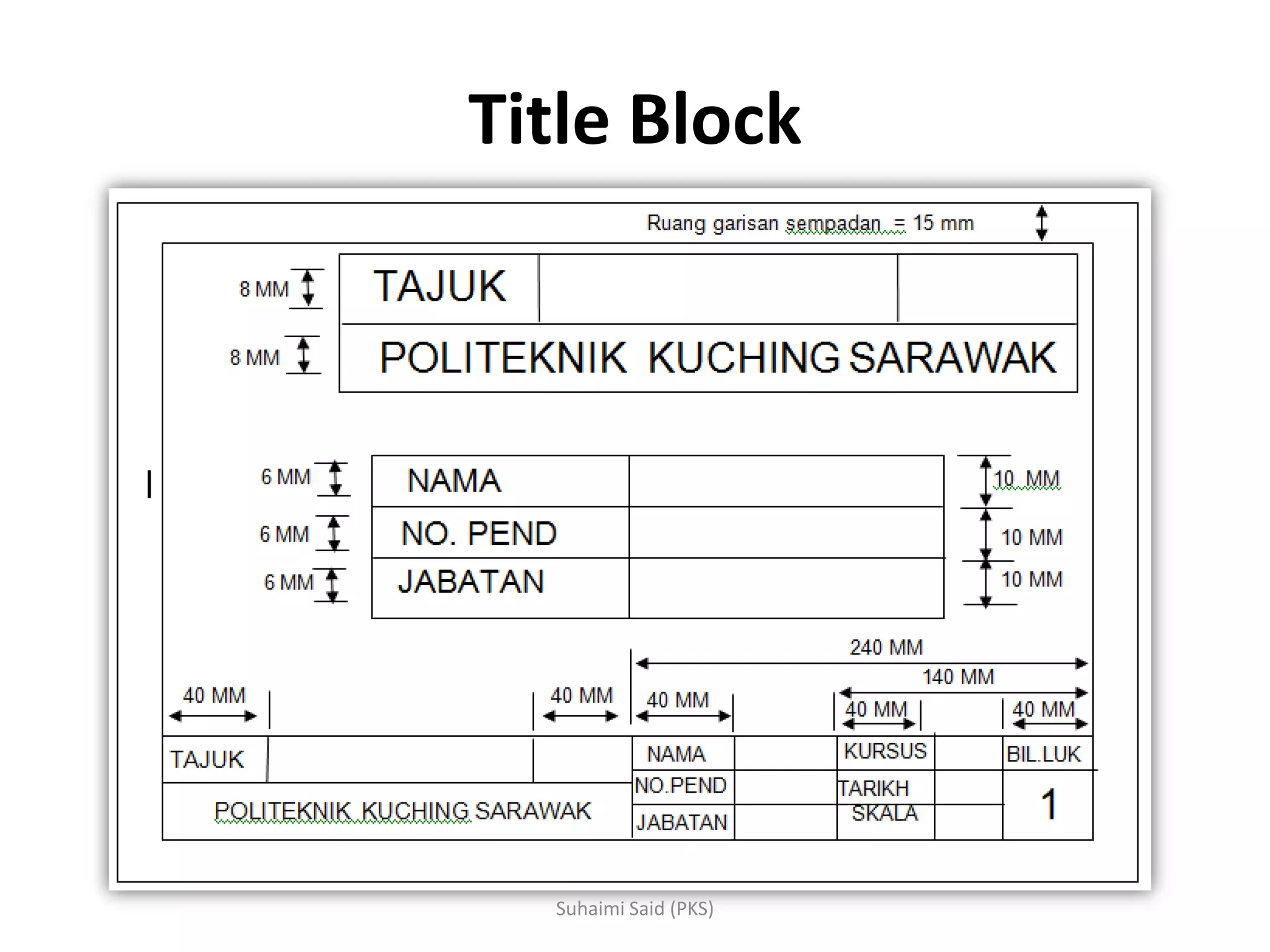
Explains the purpose of title blocks in drawings, which provide important information.
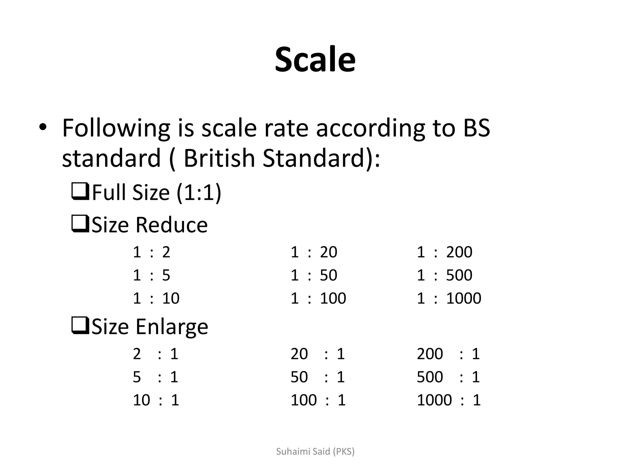
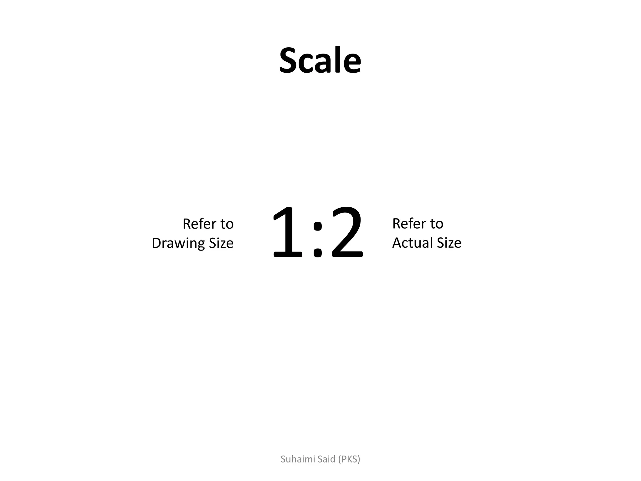
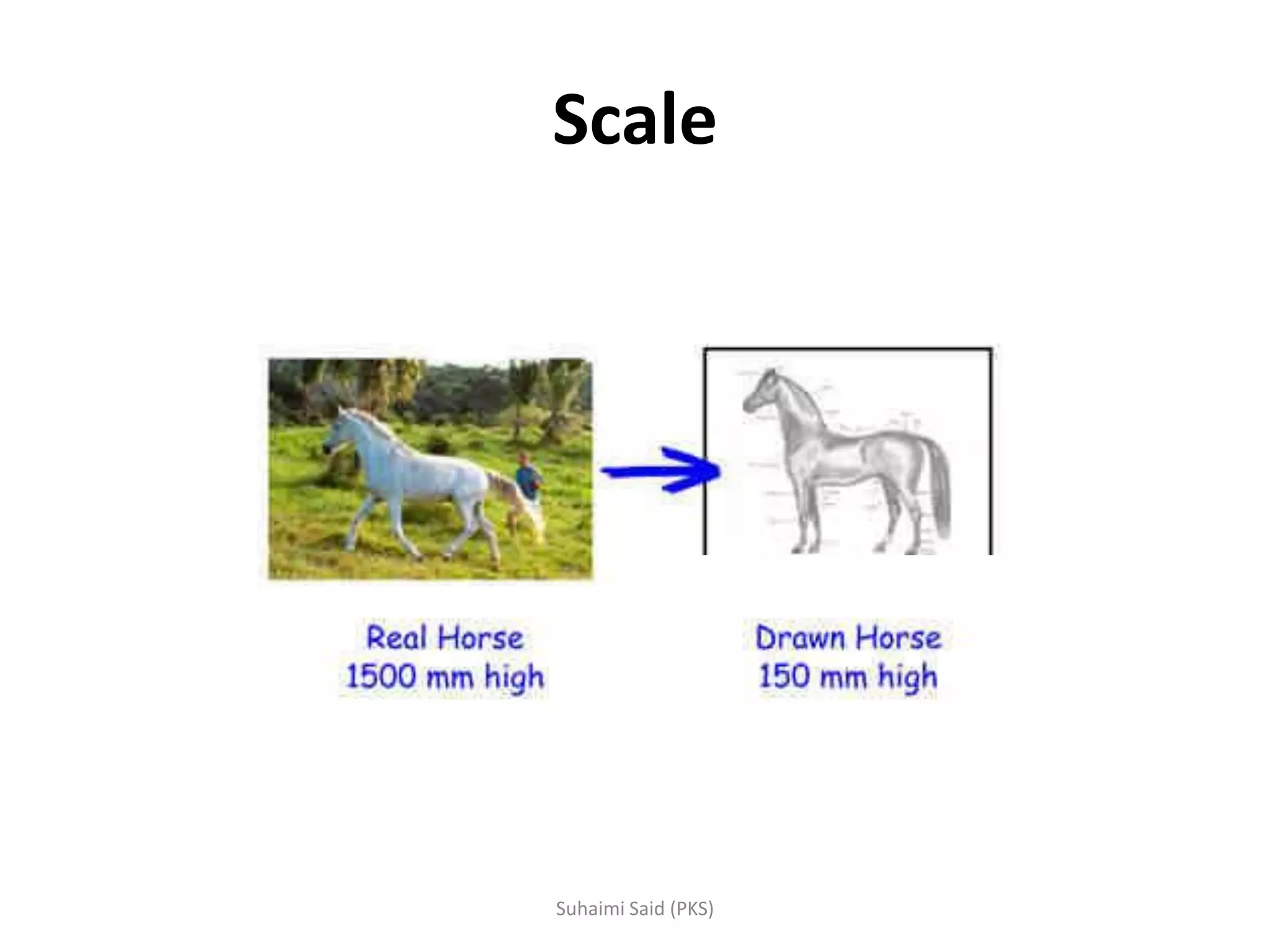
The concept of scale is introduced to depict large or small objects accurately in drawings.
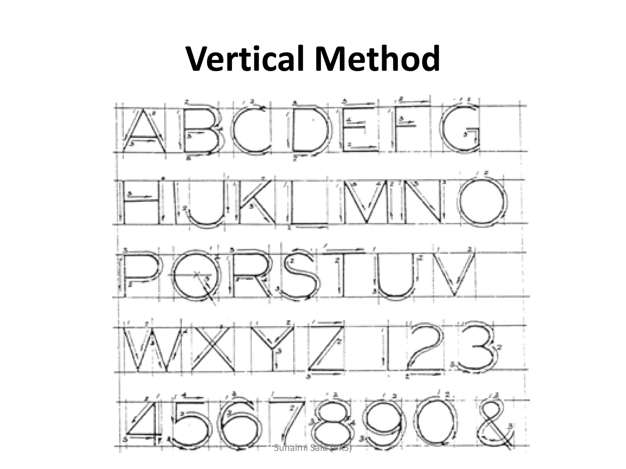
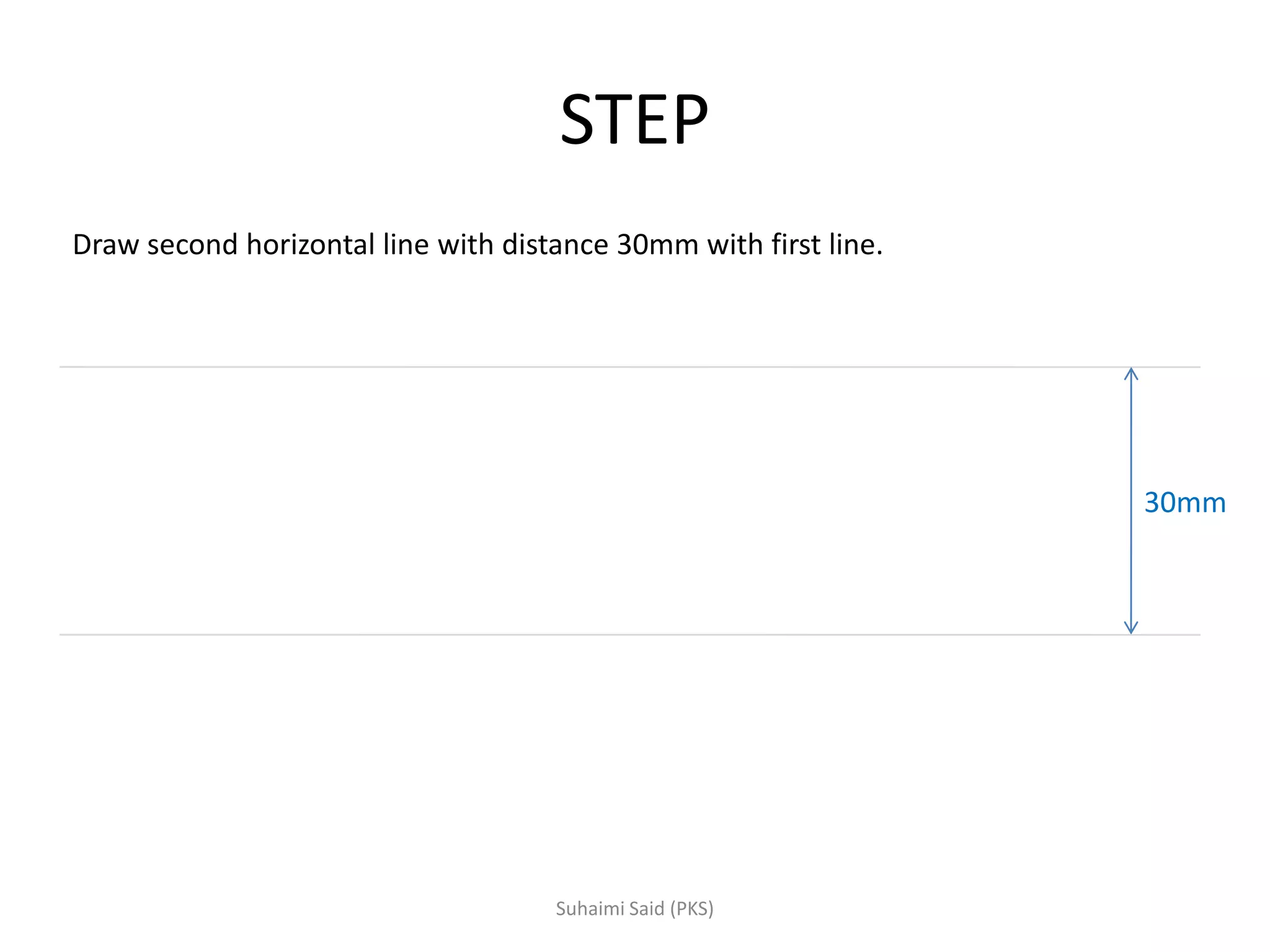
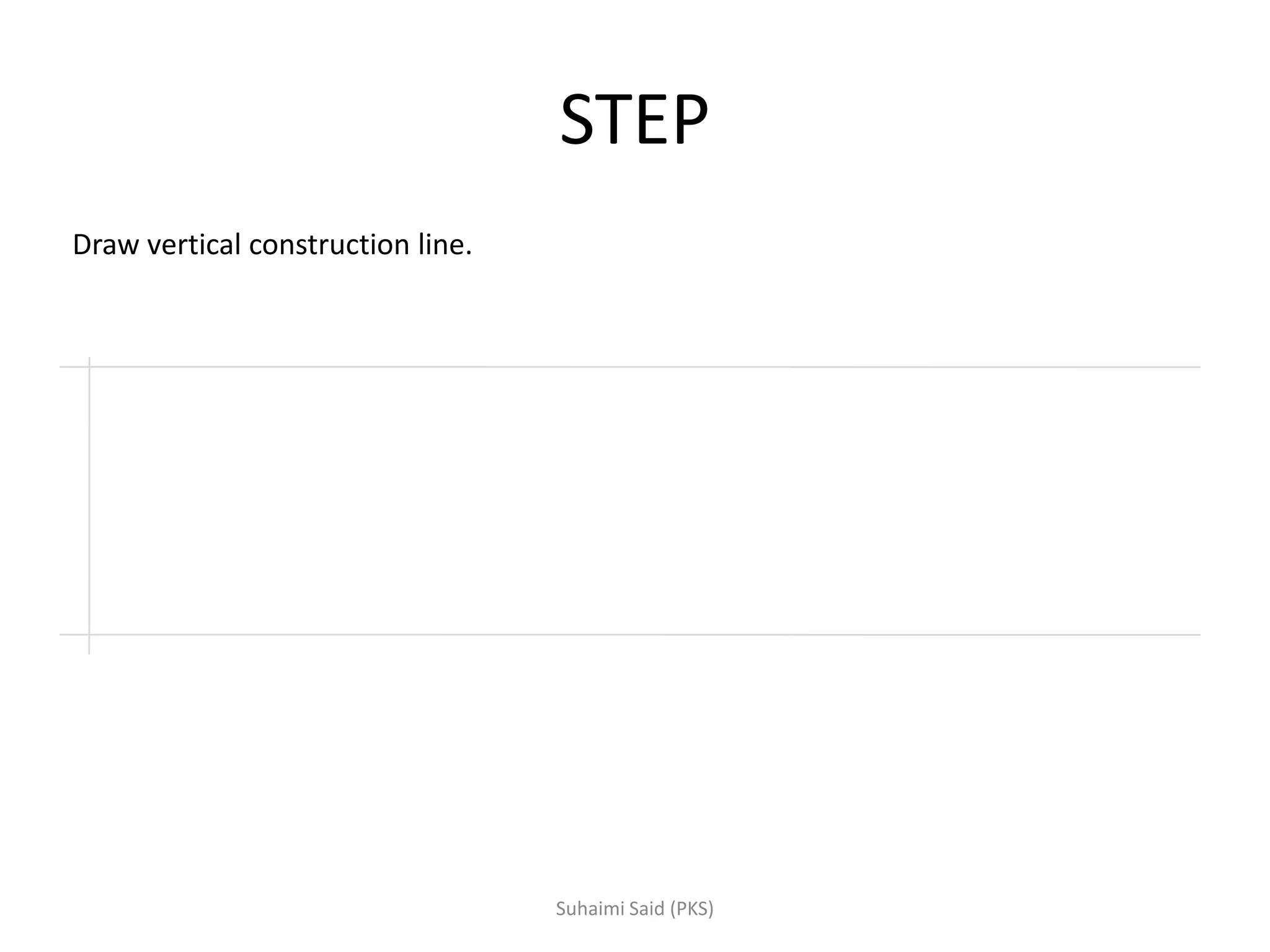
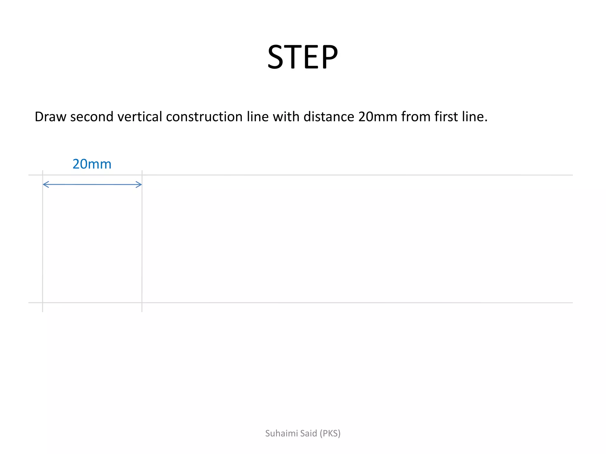
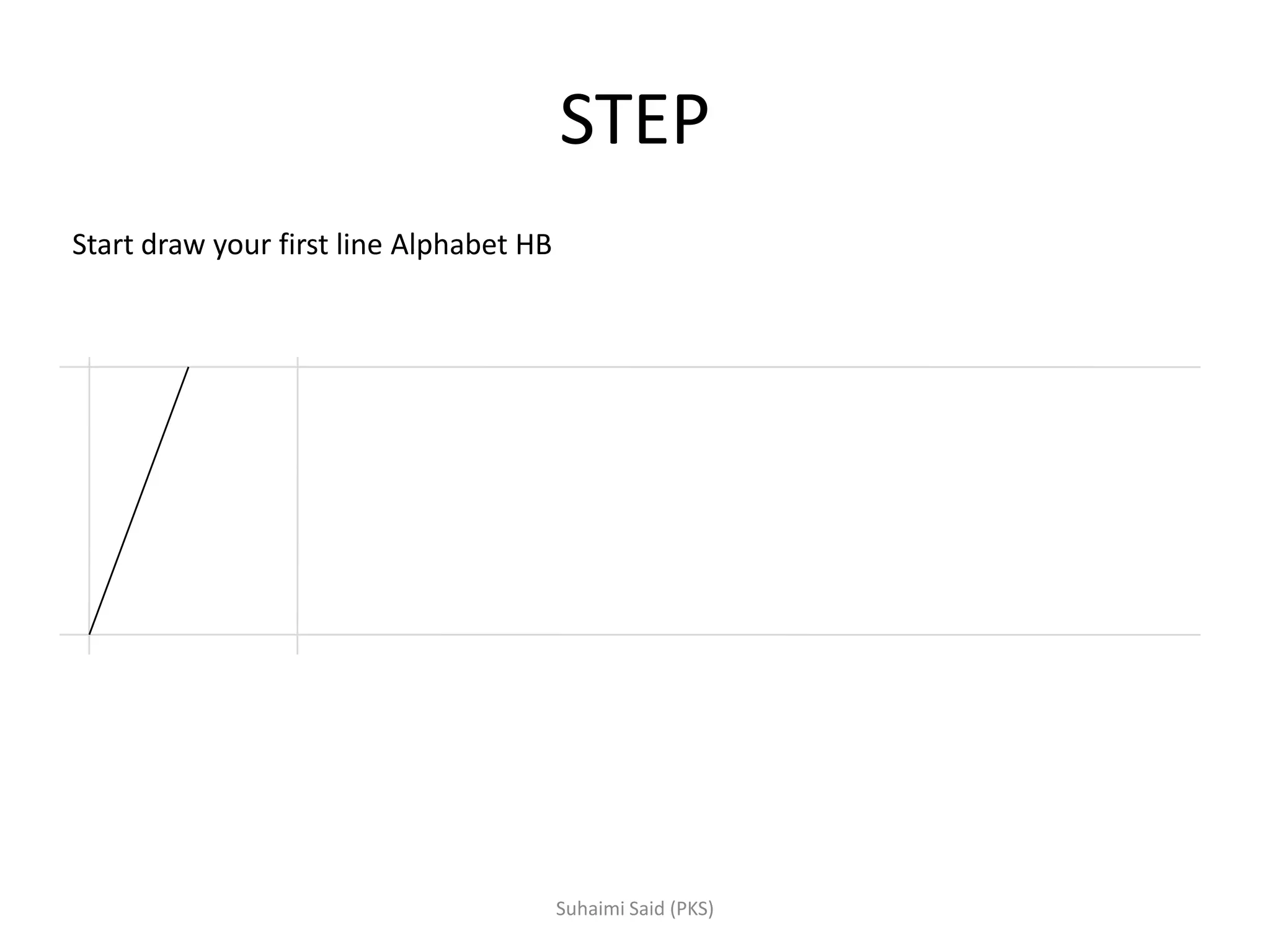
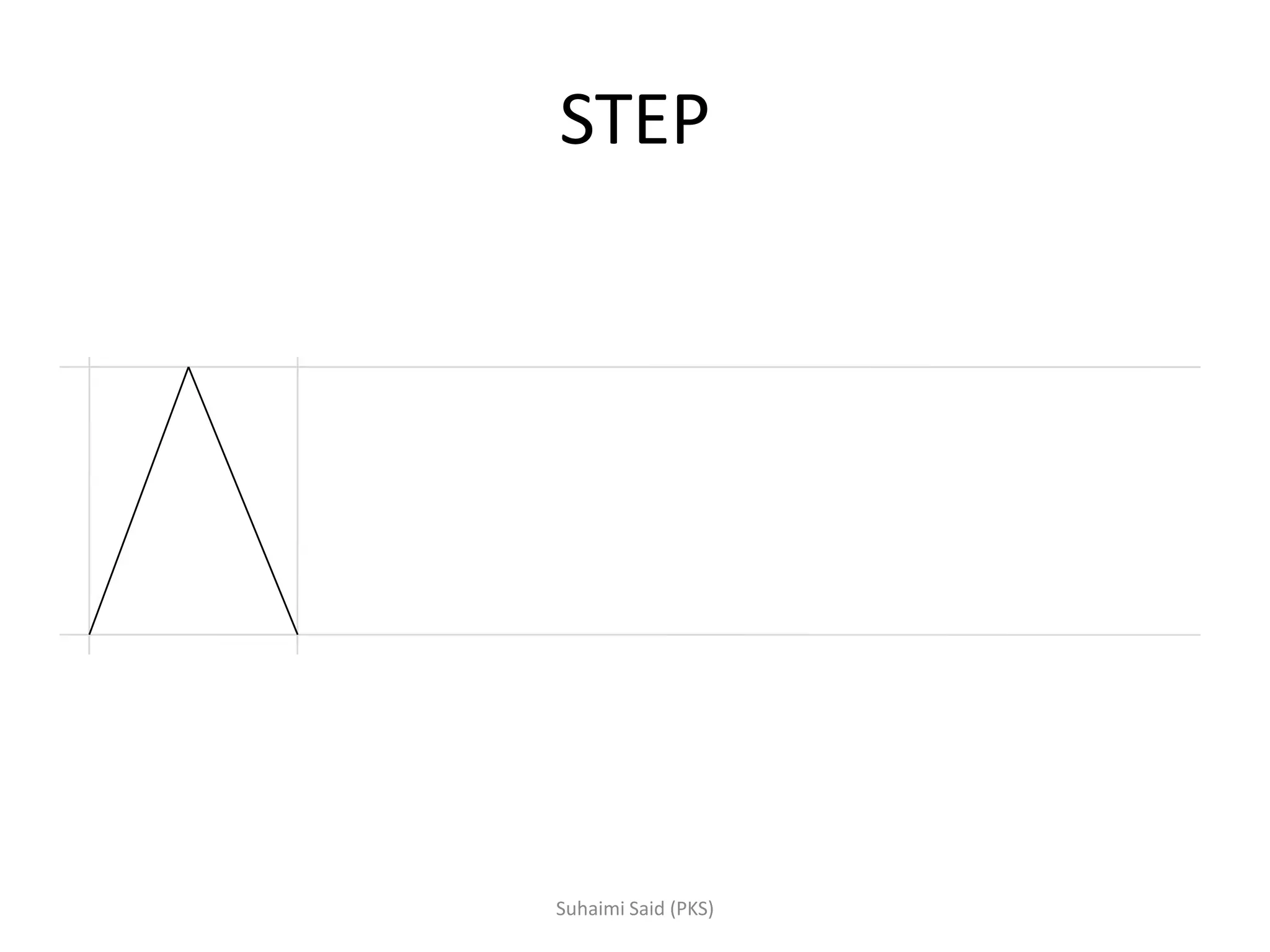
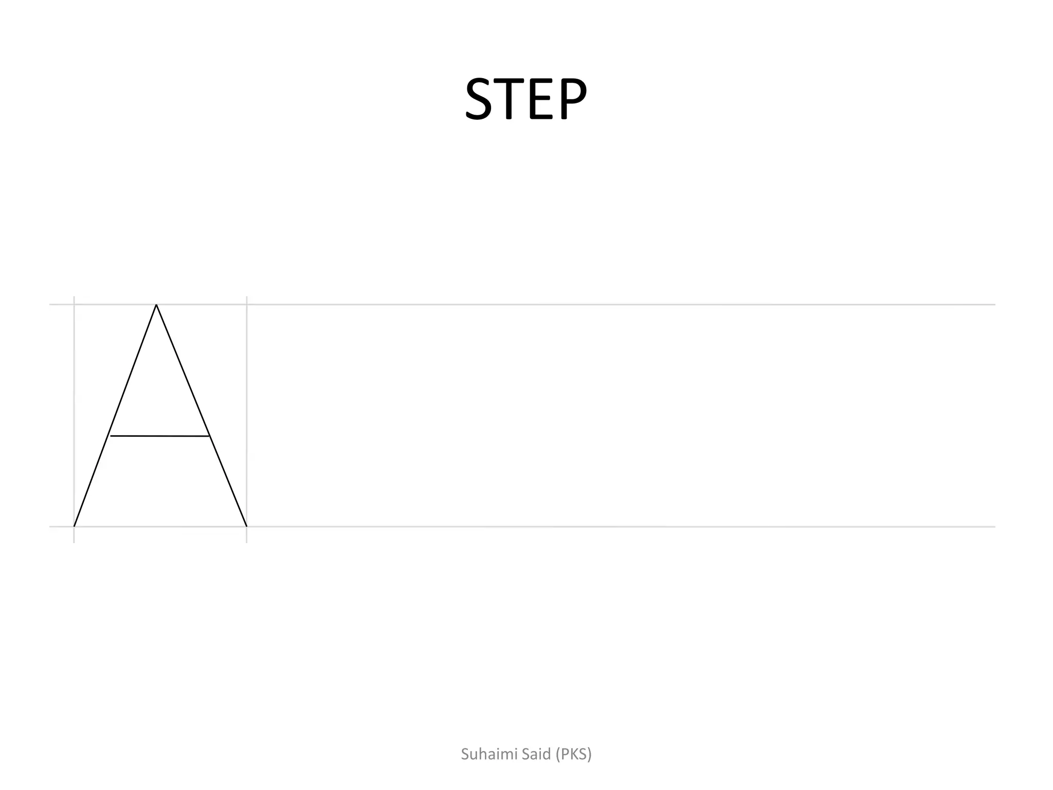
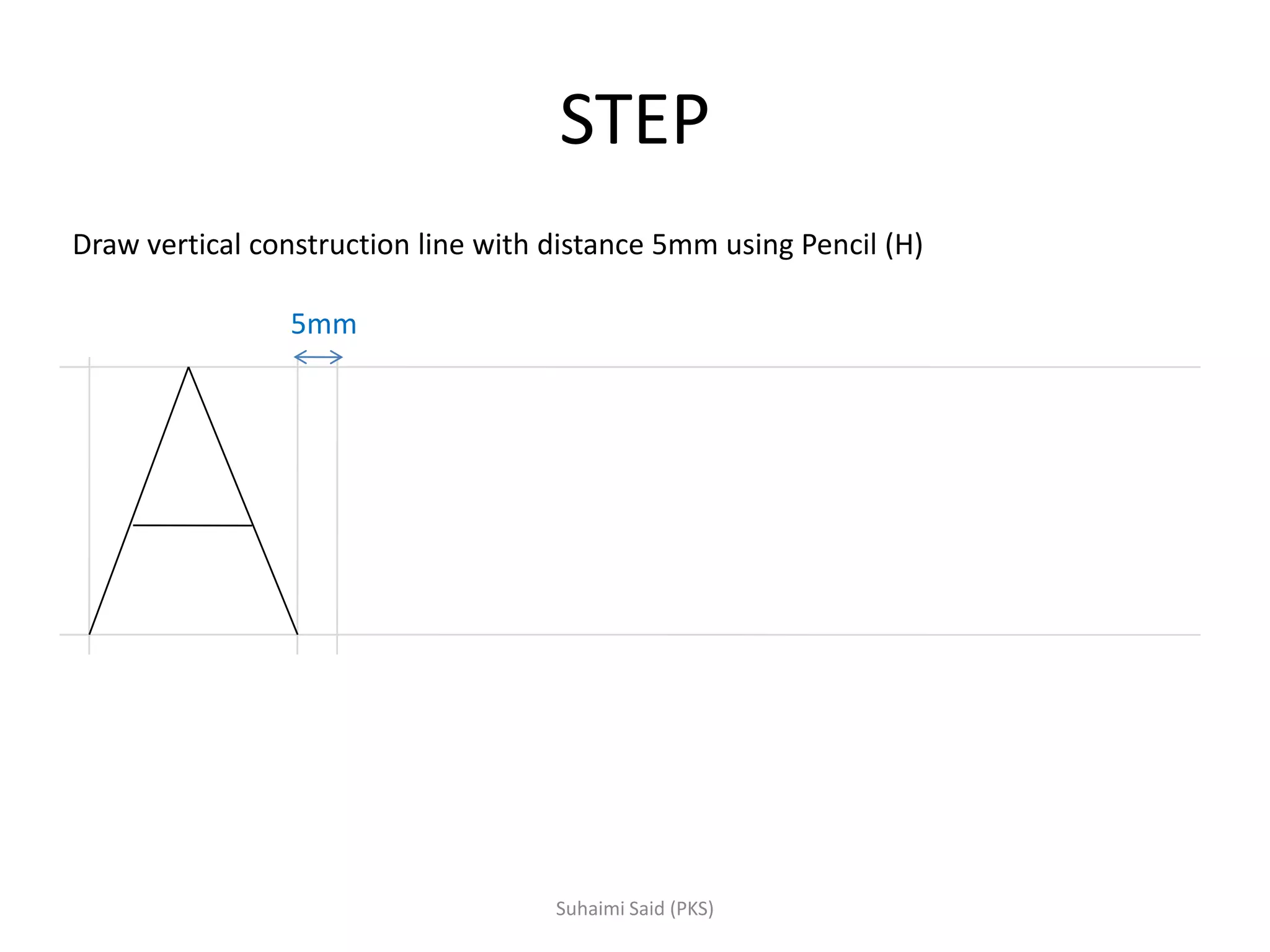
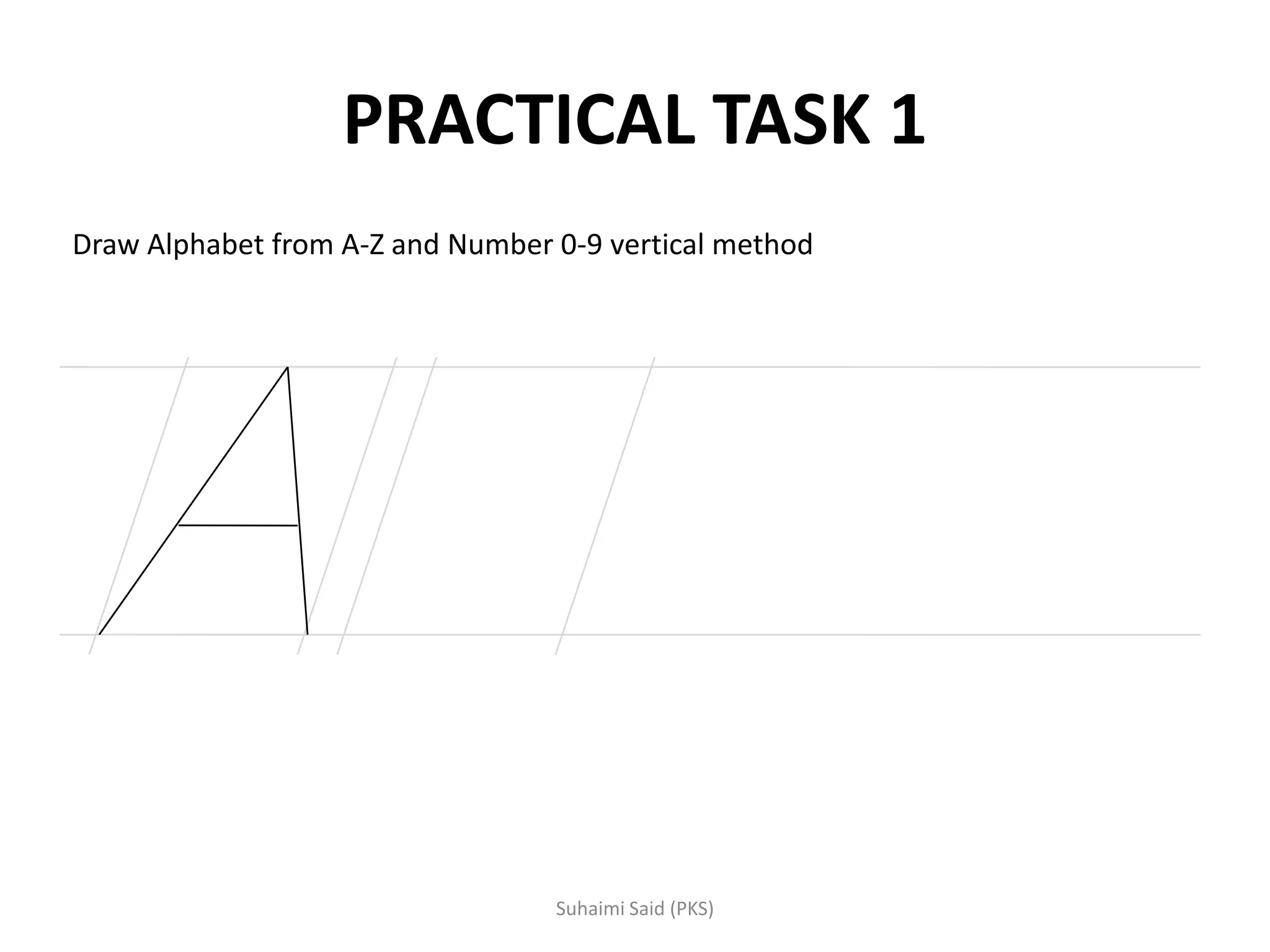
Two methodologies for lettering—vertical method explained with steps for constructing letters.
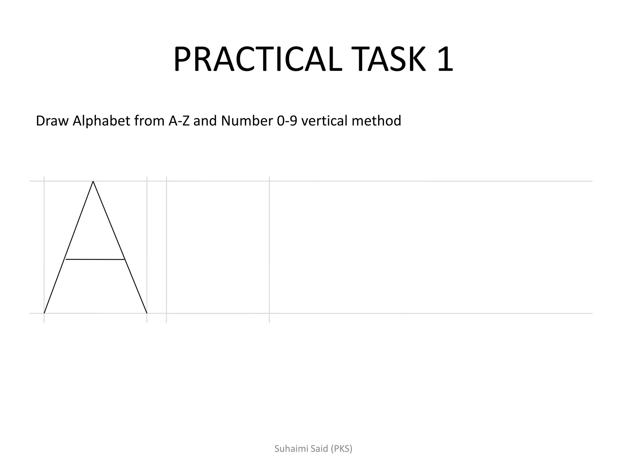
Involves a task to draw the alphabet A-Z and numbers 0-9 using the vertical method.
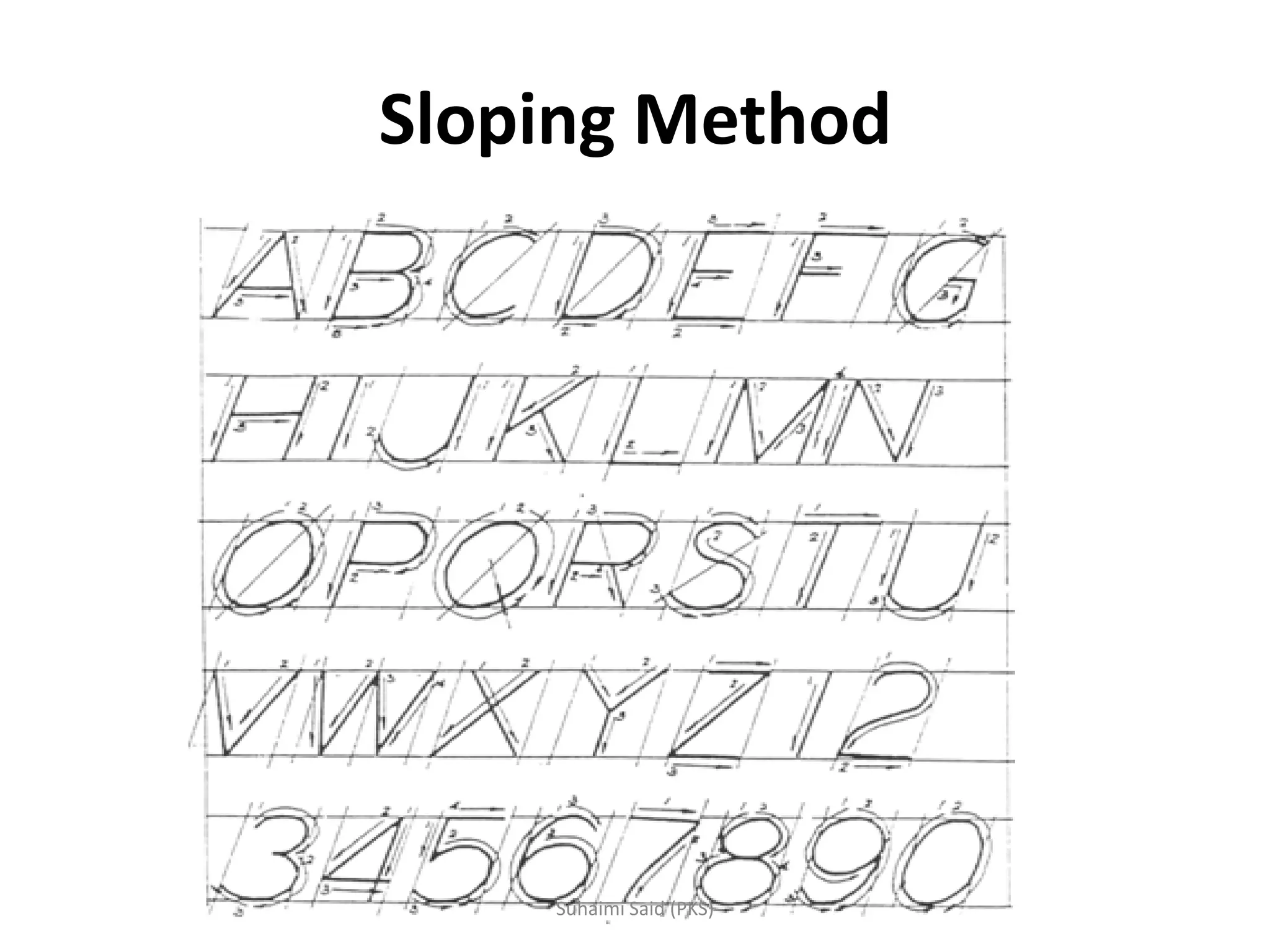
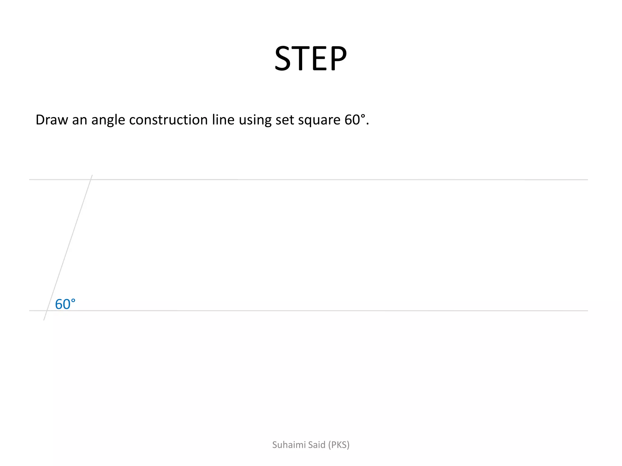
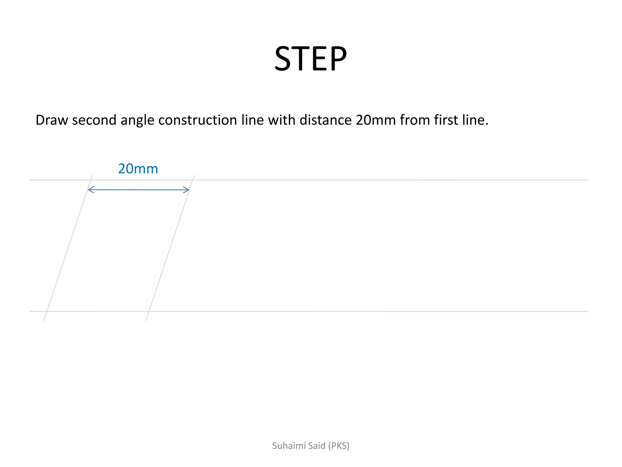
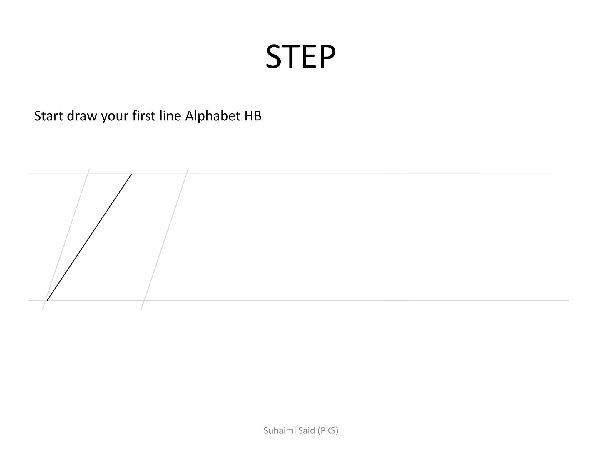
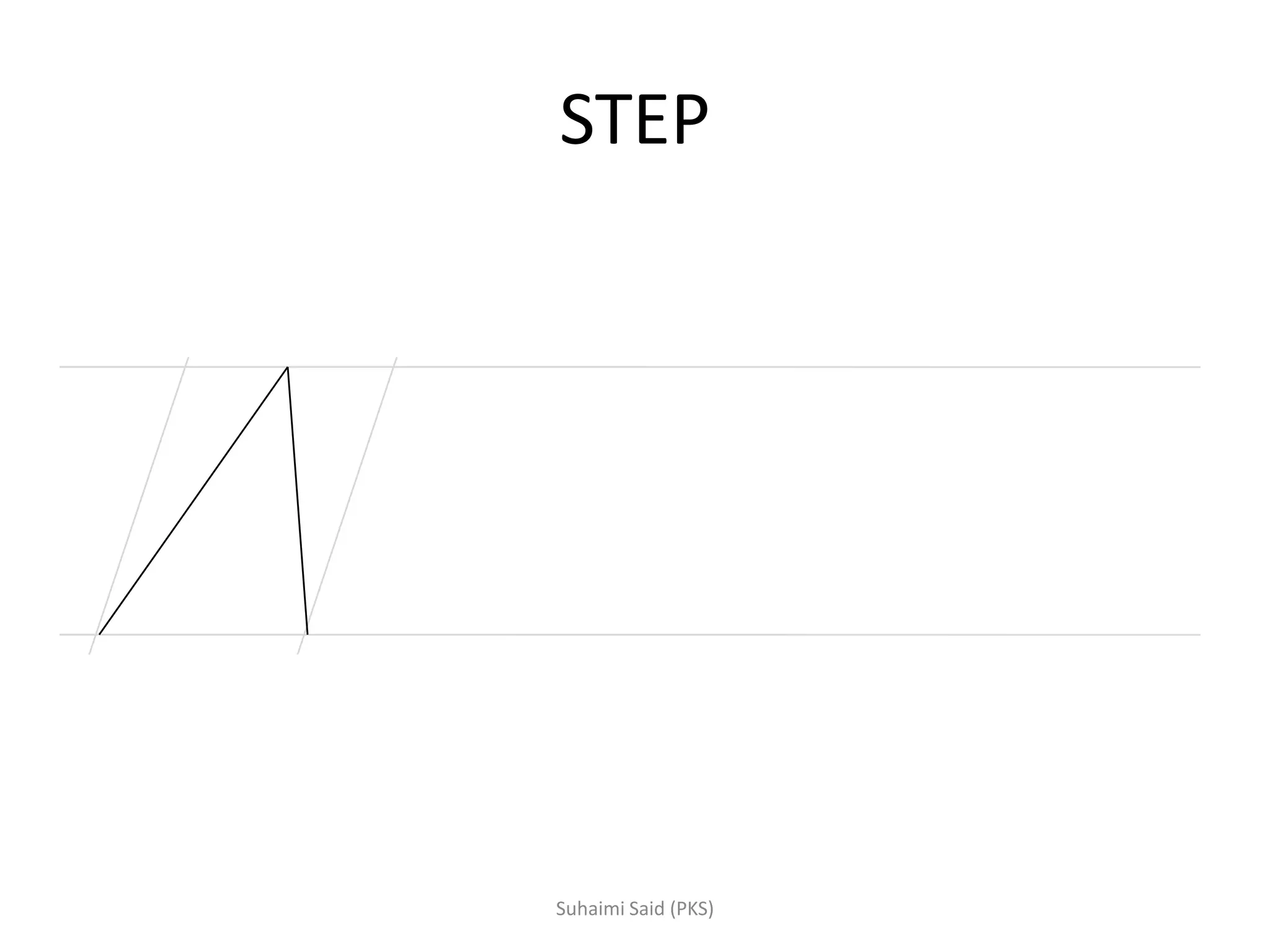
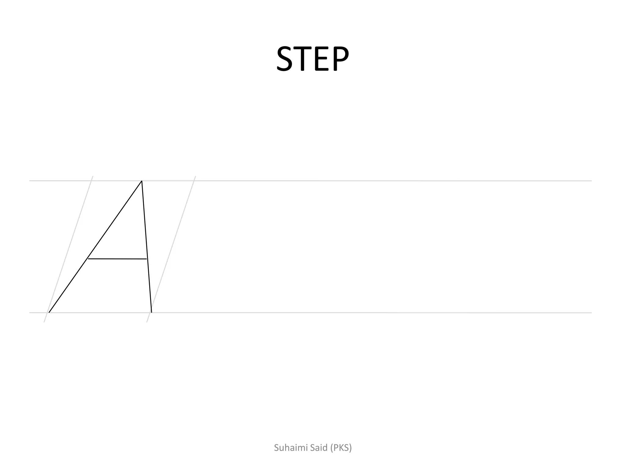
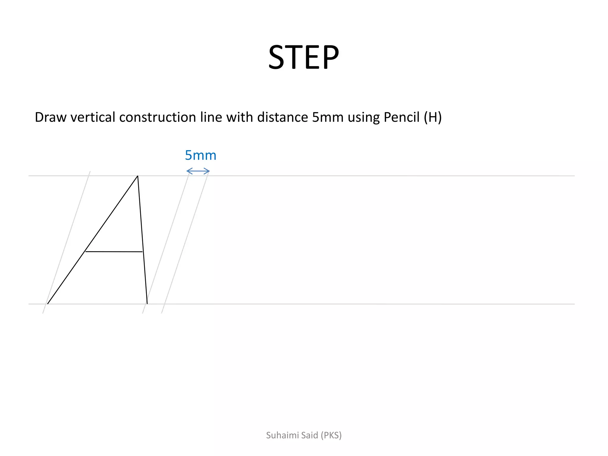
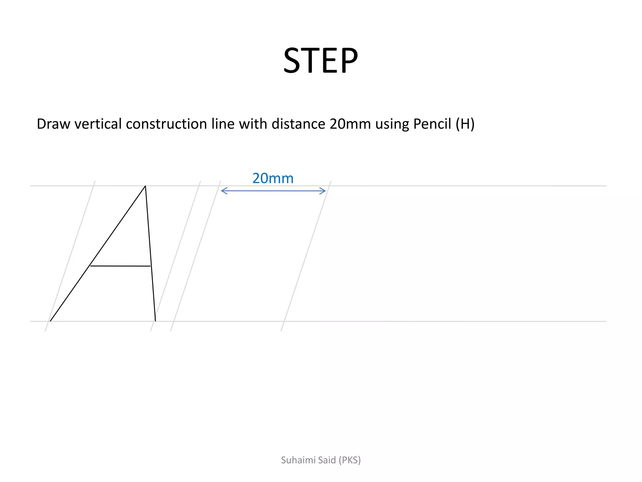
Steps to create letters using a sloping method explained with construction guidelines.
Task to draw alphabet A-Z and numbers 0-9 using the sloping method.
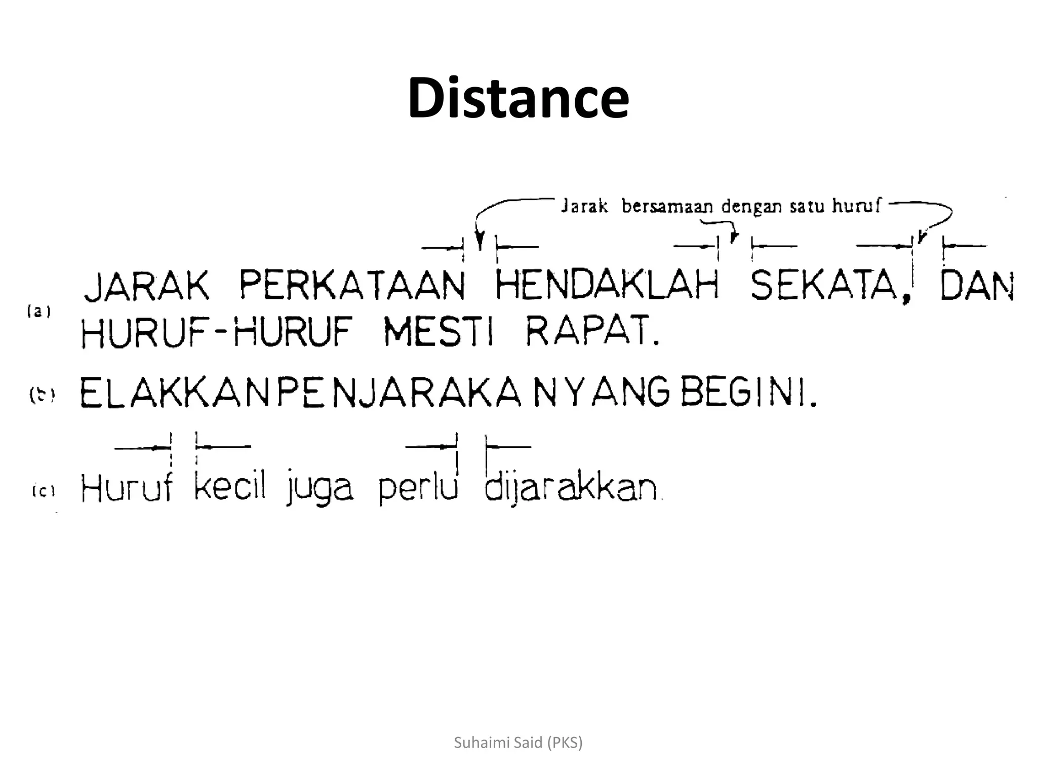
Discusses the need for distance between letters to improve legibility and avoid confusion.
Different types of lines used in engineering drawings including object, center, hidden, phantom, etc.
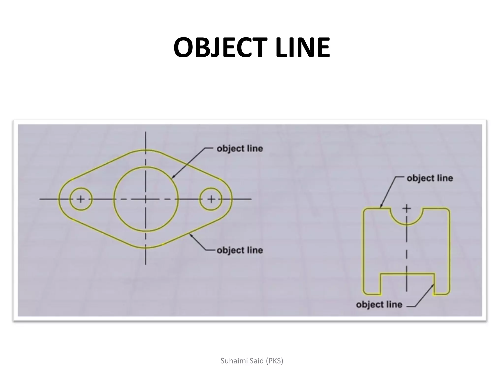
Definition and usage of object lines in drawings, representing outlines with thick continuous lines.
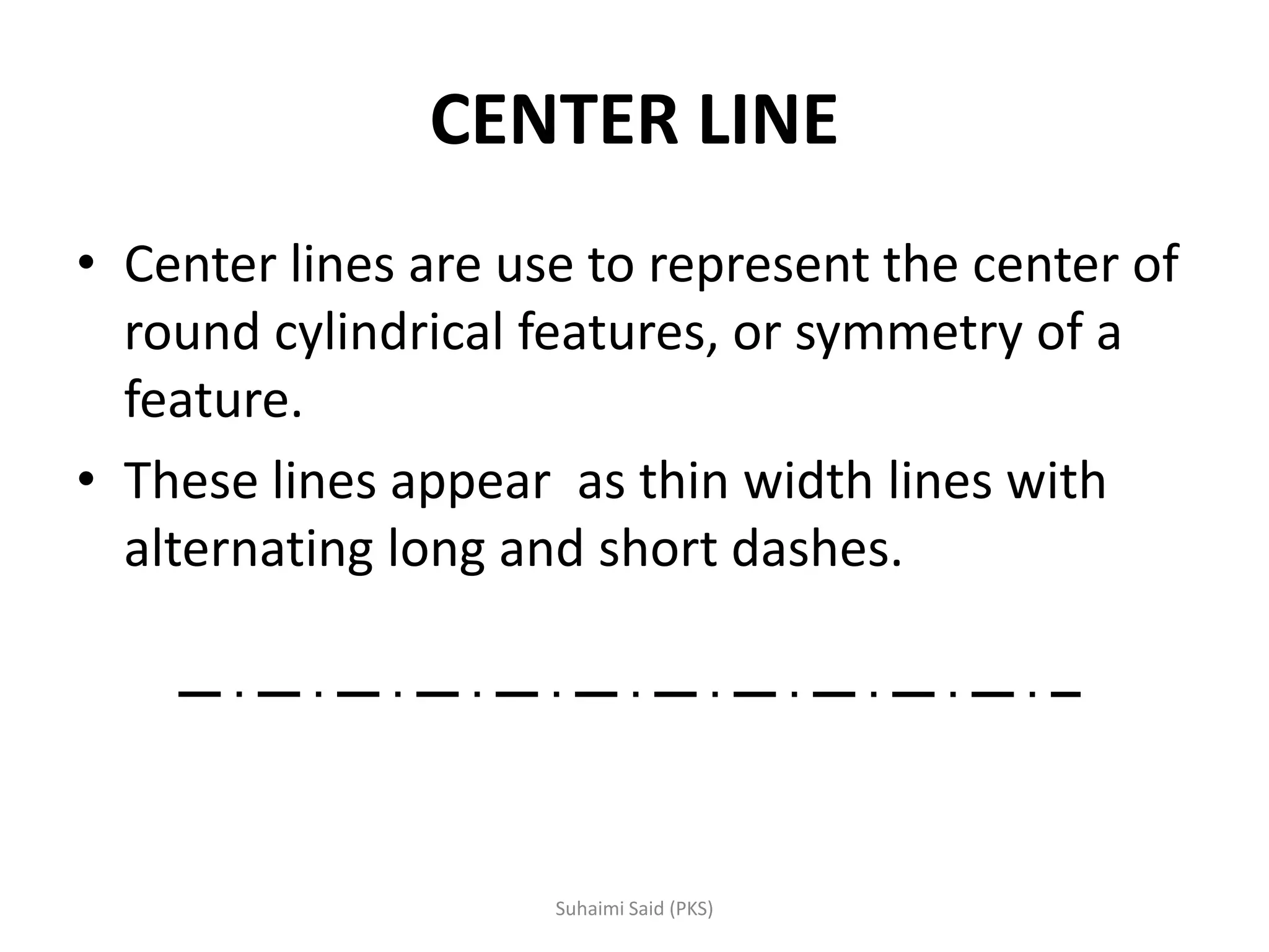
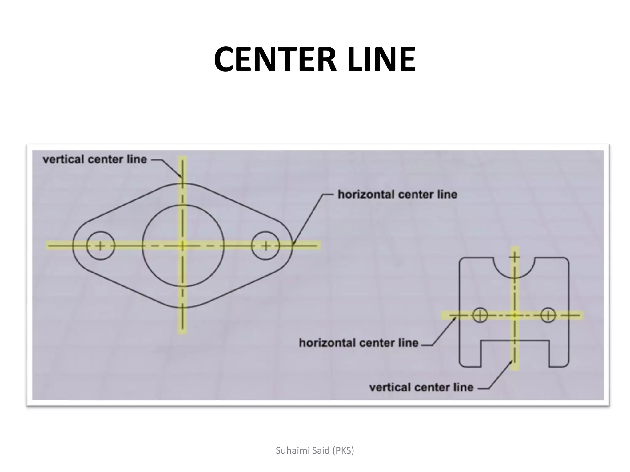
Description of center lines used for symmetrical features, appearing as thin lines with long/short dashes.
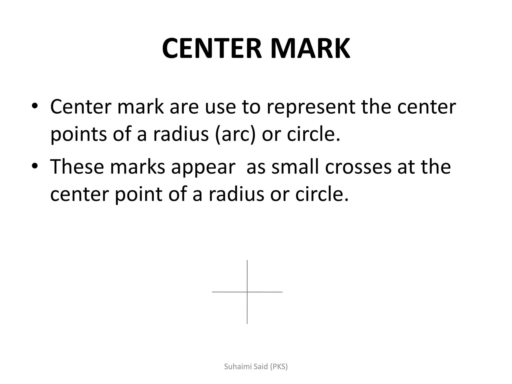
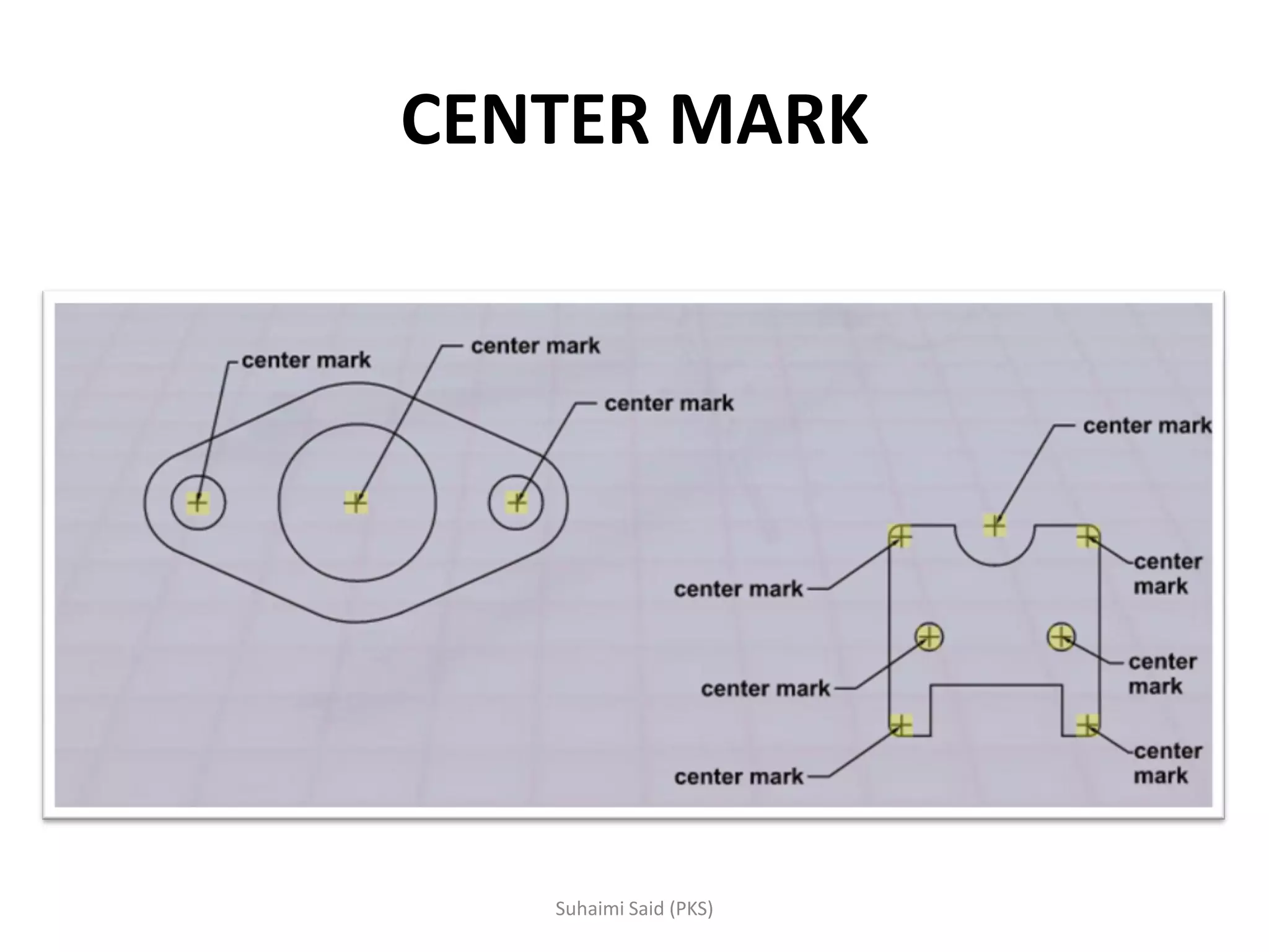
Explains the role of center marks indicating the center of arcs and circles represented as small crosses.
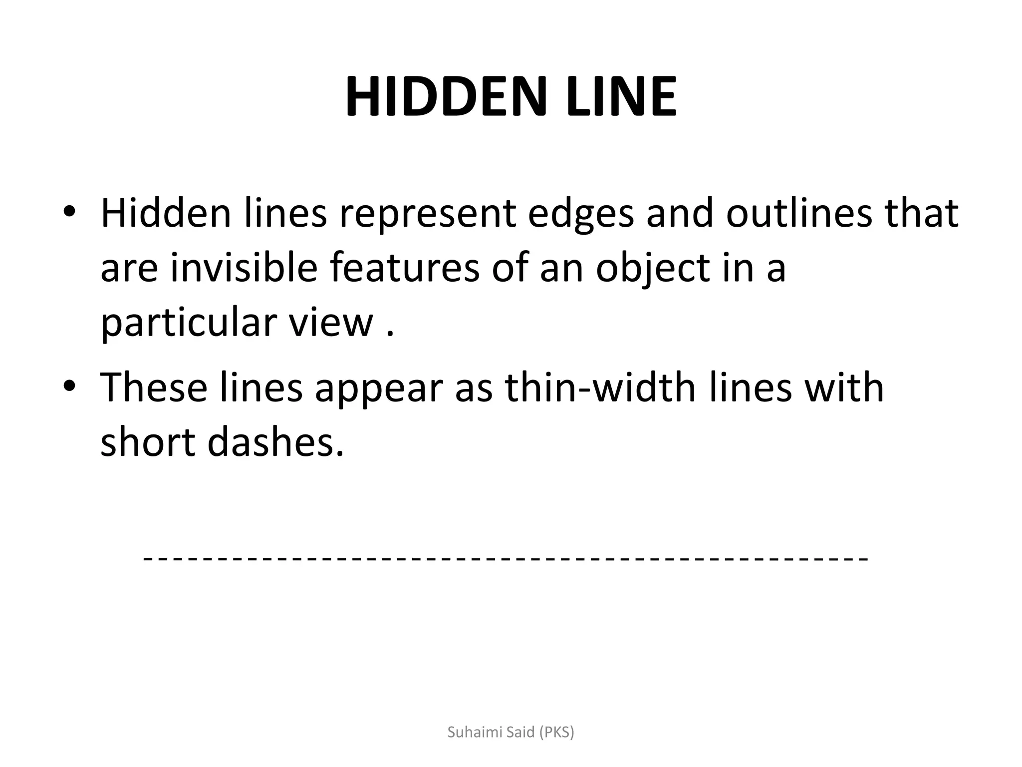
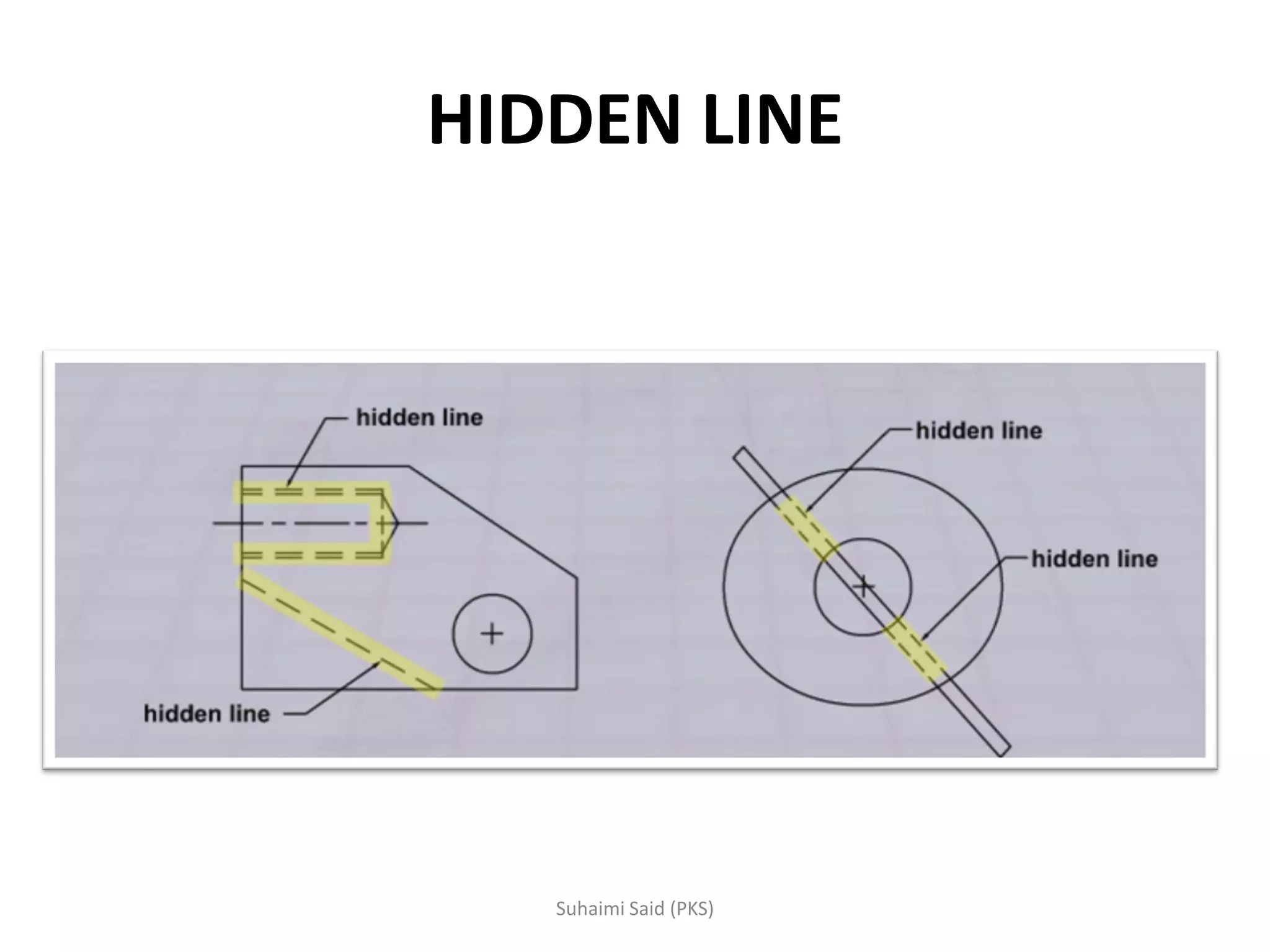
Details about hidden lines that show invisible edges and outlines, depicted with thin short dashes.
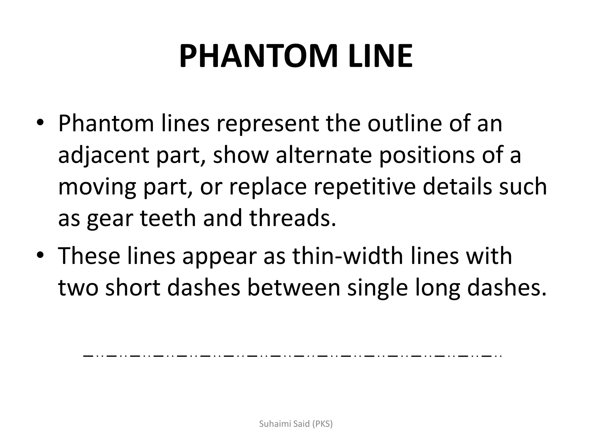
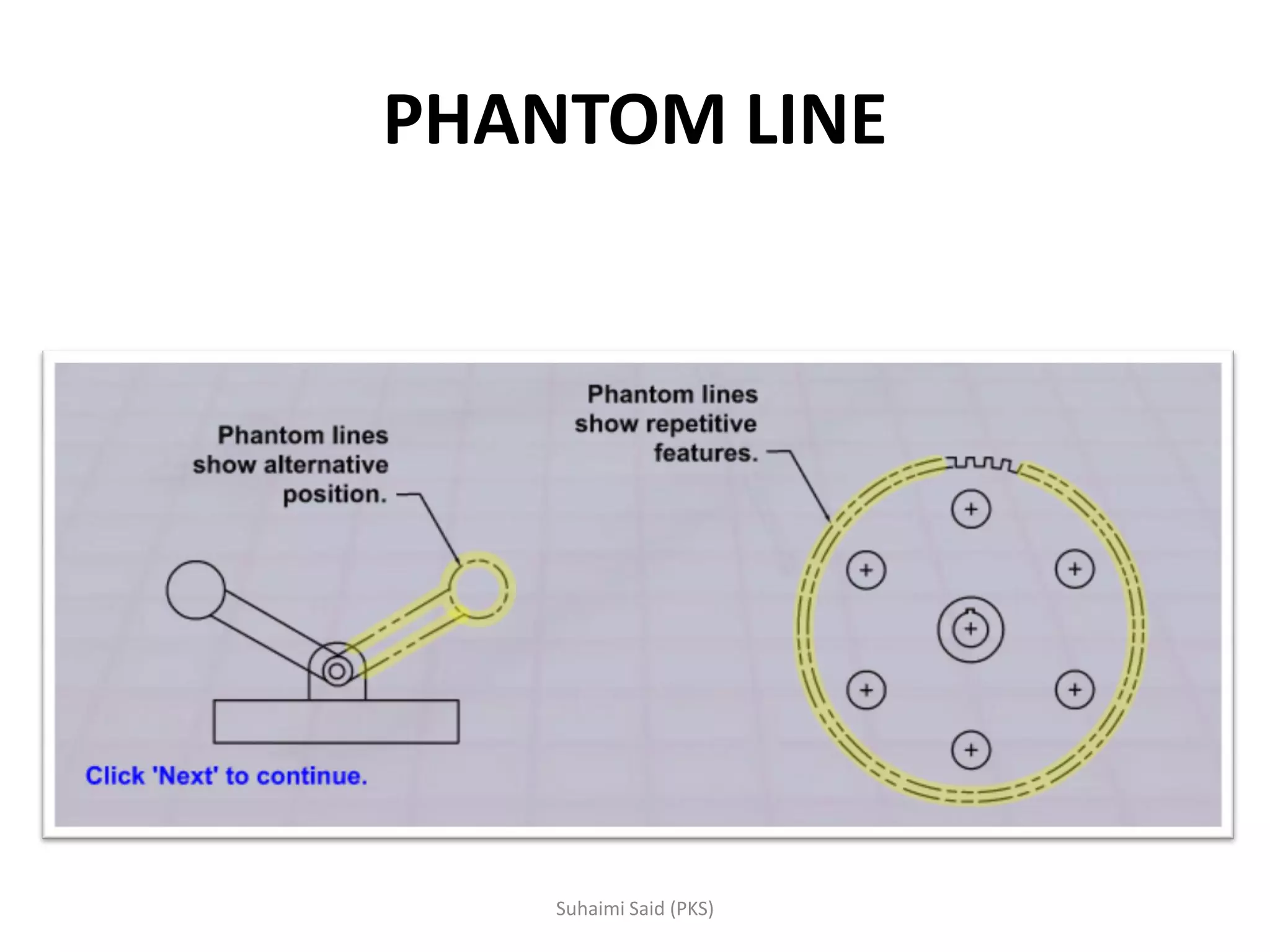
Describes phantom lines that indicate alternate positions and outlines of adjacent parts.
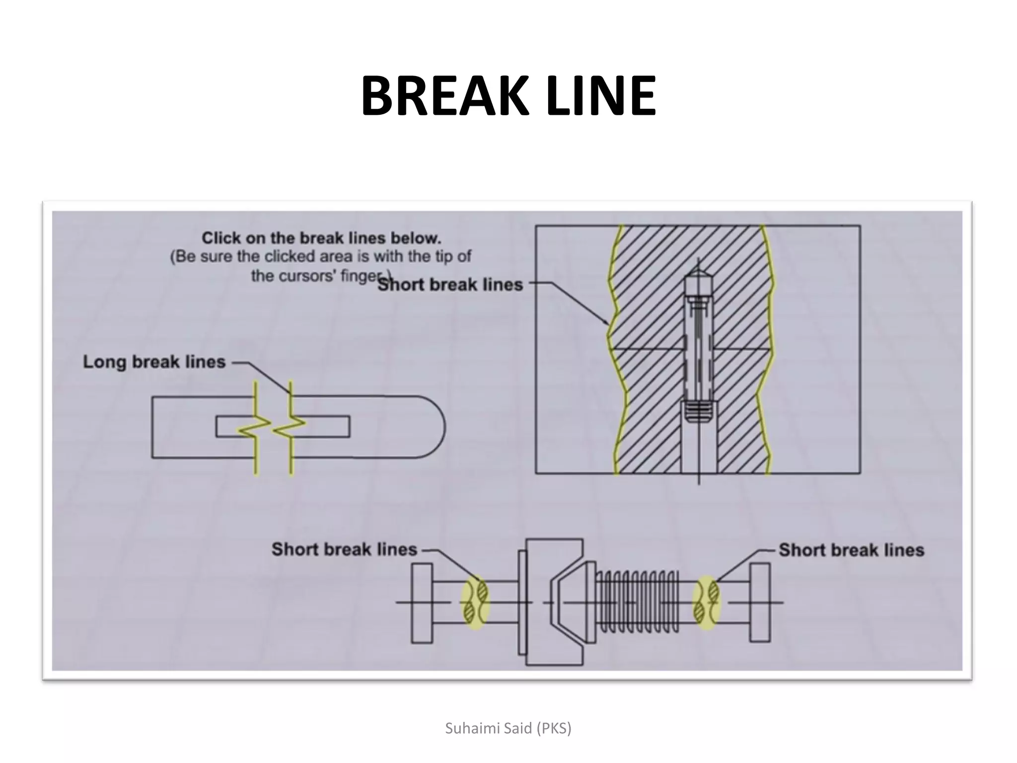
Illustrates break lines used to omit sections of an object for clarity.
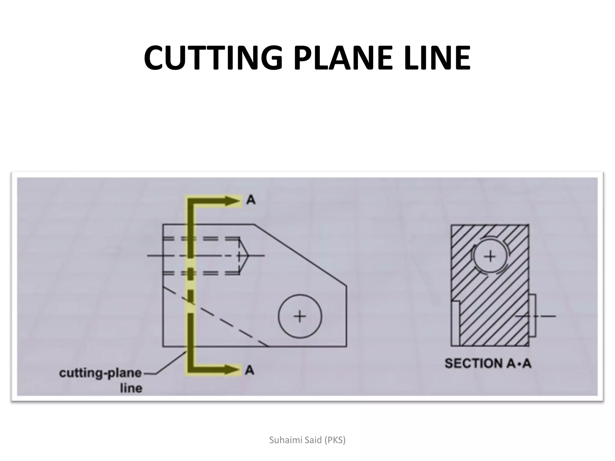
Details about cutting plane lines that show cross-section views with specific dash patterns.
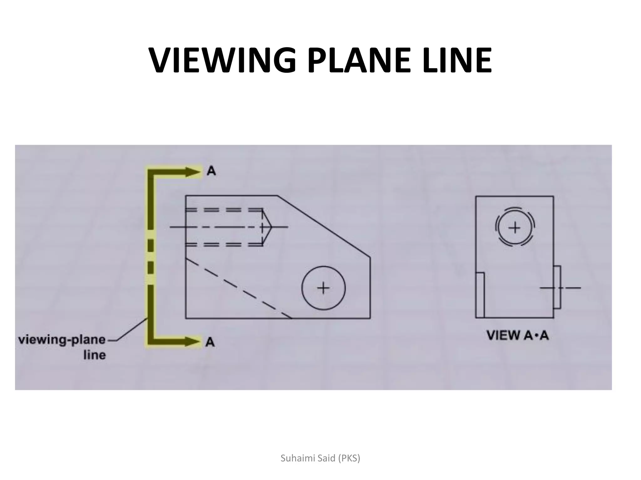
Defines viewing plane lines representing the direction of sight for specific features in drawings.
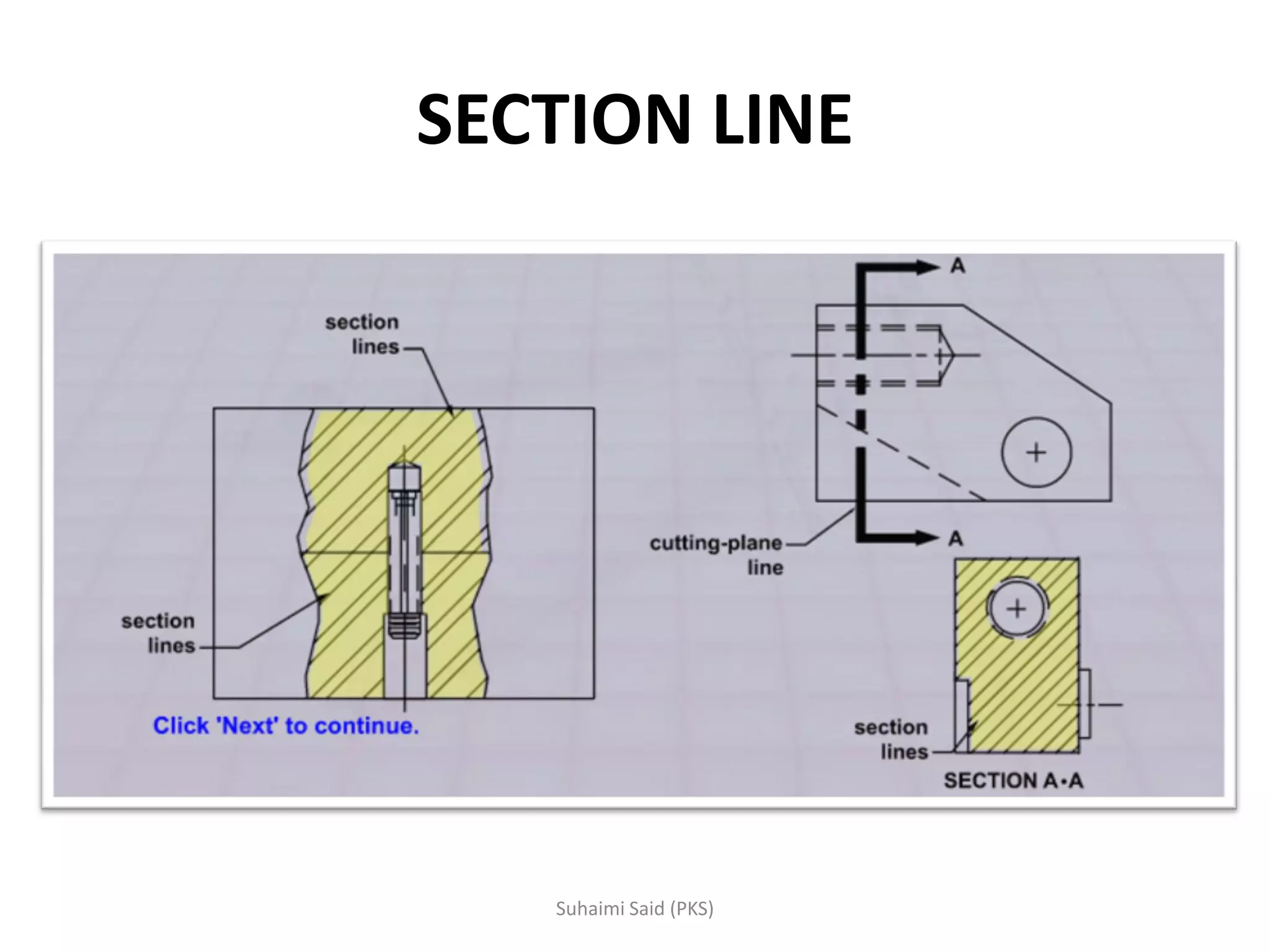
Outlines the use of section lines to show cut materials in drawings, with patterns for different materials.