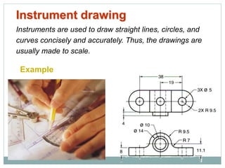
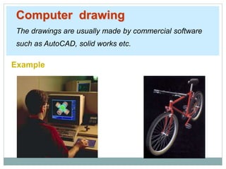
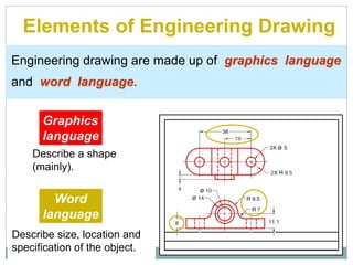
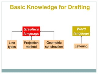
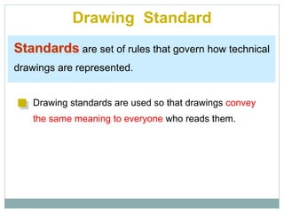
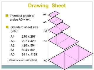
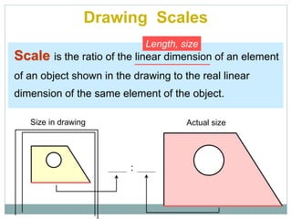
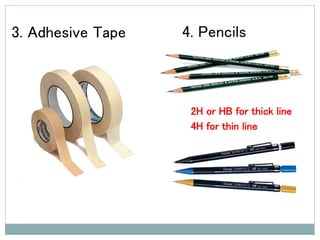
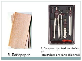
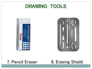
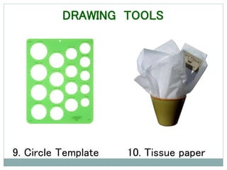
SlideShare a Scribd company logo
Overview of an Engineering Drawing
Mettu University
Technology Faculty
Mechanical Engineering Department
By Mr Leliso H.
♦ Define graphic communication
♦ Mention some types of drawing
♦ Explain the difference between different types of
drawings
♦ Mention some of the applications of technical
drawings
Objectives
•What is drawing ?
•What is graphics language ?
•List some types of drawing ?
•What is standard of drawing ?
•List types of line we use in drawing ?
•What is lettering ?
CHAPTER ONE
INTRODUCTION TO GRAPHIC
COMMUNICATION
Drawing (Graphics language)
A drawing is a graphic representation of an object,
or a part of it and is the result of creative thought by
an engineer or technician.
Any medium that uses a graphic image to aid in
conveying a message, instructions, or an idea is
involved in graphic communication.
Technically, it can be defined as “a graphic
representation of an idea, a concept or an entity which
actually or potentially exists in life. Graphic
communication involves using visual materials to
relate ideas.
Cont…
Drawing as a means of communications
• Exchange of ideas needs means of
communication. As the idea becomes technical
the usual means of communication (talk or
listen, read or write) will be less exact. For this
reason visual language is developed to be
technical and accurate means communication.
This visual language in broad term is called
graphic language.
• The v-block is to be made of cast iron and machined on
all surfaces. The overall sizes are two and one-half
inches high, three inches wide, and six inches long. A
v-shaped cut having an included angle of 90° is to be
made through the entire length of the block. The cut is
to be made with the block resting on the three inch by
six inch surface. The v-cut is to begin one-quarter inch
from the outside edges. At the bottom of the v-cut there
is to be a relief slot one-eighth inch wide by one-eighth
inch deep.
Cont…
Cont…
Effectiveness of Graphics Language
The word languages are inadequate for describing the
size, shape and features completely as well as
concisely.
1. Try to write a description of
this object.
2. Test your written description
by having someone attempt
to make a sketch from your
description.
You can easily understand that …
Graphic language in “engineering application” use
lines to represent the surfaces, edges and contours
of objects.
A drawing can be done using freehand, instruments
or computer methods.
Composition of Graphic Language
The language is known as “drawing” or “drafting” .
Graphic Language or Drafting
– It is a form of communication that is technical
and very exact.
– It is visual language
– Utilize line and symbols agreed all over the world.
Graphic communication  written or drawn
• The most common names associated with
the graphic languages are:
– Drafting : represent all graphic languages.
– Technical Drawing : Any drawing which
expresses technical ideas, including sketches,
instrument drawings, charts, and illustrations.
Eg. Technical Sketching; Freehand.
Cont…
Types of Drawing
There are two basic types of drawings:
•Artistic drawings and
•Technical drawings.
Artistic Drawings
Artistic Drawings range in scope from the simplest line
drawing to the most famous paintings. Regardless of their
complexity, artistic drawings are used to express the feelings,
beliefs, philosophies, and ideas of the artist.
In order to understand an artistic drawing, it is sometimes
necessary to first understand the artist.
Cont…
Cont…
Technical Drawings
The technical drawing, on the other hand, is not subtle, or
abstract. It does not require an understanding of its creator,
only an understanding of technical drawings.
A technical drawing is a means of clearly and concisely
communicating all of the information necessary to
transform
an idea or a concept in to reality. Therefore, a technical
drawing often contains more than just a graphic
representation of its subject. It also contains dimensions,
notes and specifications.
Cont…
Types of Technical
Drawings
• Three Basic Types of
Technical Drawings
– Freehand sketches
– Instrument drawings
– Computer drawings
and models
Freehand drawing
The lines are sketched without using instruments other
than pencils and erasers.
Example
Instrument drawing
Instruments are used to draw straight lines, circles, and
curves concisely and accurately. Thus, the drawings are
usually made to scale.
Example
Computer drawing
The drawings are usually made by commercial software
such as AutoCAD, solid works etc.
Example
Engineering
Drawing
Elements of Engineering Drawing
Engineering drawing are made up of graphics language
and word language.
Graphics
language
Describe a shape
(mainly).
Word
language
Describe size, location and
specification of the object.
Basic Knowledge for Drafting
Graphics
language
Word
language
Line
types
Geometric
construction Lettering
Projection
method
Drawing Standard
Drawing Standard
Standards are set of rules that govern how technical
drawings are represented.
Drawing standards are used so that drawings convey
the same meaning to everyone who reads them.
Drawing Sheet
Trimmed paper of
a size A0 ~ A4.
Standard sheet size
(JIS)
A4 210 x 297
A3 297 x 420
A2 420 x 594
A1 594 x 841
A0 841 x 1189
A4
A3
A2
A1
A0(Dimensions in millimeters)
Drawing Scales
Scale is the ratio of the linear dimension of an element
of an object shown in the drawing to the real linear
dimension of the same element of the object.
Size in drawing Actual size
Length, size
:
Drawing Scales
Designation of a scale consists of the word “SCALE”
followed by the indication of its ratio, as follow
SCALE 1:1 for full size
SCALE X:1 for enlargement scales (X > 1)
SCALE 1:X for reduction scales (X > 1)
Dimension numbers shown in the drawing are correspond
to “true size” of the object and they are independent of
the scale used in creating that drawing.
 Definition:
- Line is the most basic design 'tool'.
- A line has length, width, tone, and texture.
- It may divide space, define a form, describe contour,
suggest direction.
Examples:
"A line is a dot that went for a walk." - Paul Klee.
 1. Visible Lines: Dark, heavy lines with approximate width 0.6mm.
 Show the outline and shape of an object.
 Define features you can see in a particular view.
 2. Hidden Lines: Light/medium, narrow, short dashed lines with
approximate width 0.3mm.
 Shows the outline of a feature that can not be seen in a particular
view.
 Used to help clarify a feature, but can be omitted if they clutter a
drawing.
 3. Section Lines: Thin lines usually drawn at a 45 degree angle.
Indicate the material that has been cut through in a sectional
view.
 4. Center Lines: Thin line consisting of long and short dashes.
Shows the center of holes, slots, paths of rotation, and
symmetrical objects.
5. Dimension Lines: Thin, dark lines.
 Show the length, width, and height of the features of an object.
 Terminated with arrowheads at the end.
6. Extension Lines: Thin line used to show the starting and
stopping points of a dimension.
 Must have at least a 1mm space between the object and the
extension line.
Dimension
Line
Extension
Line
7. Leader Lines: Thin lines.
 Used to show the dimension of a feature or a note that is too large
to be placed beside the feature itself.
8. Cutting Plane Lines: Thick broken line that is terminated with
short 90 degree arrowheads.
 Shows where a part is mentally cut in half to better see the interior
detail.
Leader Line
9. Break Lines: Used to break out sections for clarity or for
shortening a part.
 Three types of break lines with different line weights.
 a. Short Breaks. Thick wavy line.
 Used to break the edge or surface of a part for clarity of a hidden
surface.
 b. Long Breaks. Long, thin lines.
 Used to show that the middle section of an object has been
removed so it can be drawn on a smaller piece of paper.
 c. Cylindrical Breaks. Thin lines.
 Used to show round parts that are broken in half to better clarify
the print or to reduce the length of the object.
10. Phantom Lines: Thin lines made up of long dashes alternating
with pairs of short dashes.
 Three purposes in drawings.
1.To show the alternate position of
 moving parts.
2. To show the relationship of parts
 that fit together.
3.To show repeated detail.
 Phantom lines can show where a part is
moving to and from.
 Eliminates the confusion of thinking there may be 2 parts instead of
just 1.
Phantom Lines
Drawing Tools
 In engineering drawing any object is represented by
straight lines and/or curves. These lines should be
drawn as accurate as possible by the help of drawing
instruments.
 Quality of a drawing depends to a large extent on
the quality , adjustment, proper use and care of
drawing instruments.
DRAWING TOOLS
DRAWING BOARD
Drawing tables come in many
different size and design. It could
be fixed, movable, with drawer,
adjustable, etc.
They are used to attach drawing
sheet.
Keep your drawing table clean
and dry not to affect your
drawing quality.
Don’t use blades to cut
drafting tapes on drawing
table.
1. T-Square
– They can be made from different
materials, mostly from wood or
plastic.
– Parts: blade and head
– two edges of the blade should be
parallel.
– The head is fixed at 900 to the
blade
– The cleanness of your T –square
greatly affect your drawing
quality and cleanliness.
2. Triangles
Triangles
Used to draw lines at
standard angles and by
connecting any two points
3. Adhesive Tape 4. Pencils
2H or HB for thick line
4H for thin line
5. Sandpaper
6. Compass used to draw circles
or
arcs (which are parts of a circle)
7. Pencil Eraser 8. Erasing Shield
DRAWING TOOLS
9. Circle Template 10. Tissue paper
DRAWING TOOLS
11. Sharpener 12. Clean paper
DRAWING TOOLS
A few basic points for a drawing
• Should be complete and unambiguous
• Should be neat and easy to read
• Use only as many views as necessary to
show all required detail
• Apply tolerances realistically - overly
tight tolerances can add a great deal of
additional cost with little or not added
value to the part
ABCDEFGHIJKLMNOPQRS
TUVWXYZABCDEFGHIJKL
MNOPQRSTUVWXYZABCD
ABCDEFGHIJKLMNOPQRS
TUVWXYZABCDEFGHIJKL
MNOPQRSTUVWXYZABCD
EF
Lettering
Text on Drawings
Text on engineering drawing is used :
To communicate nongraphic information.
As a substitute for graphic information, in those instance
where text can communicate the needed information
more clearly and quickly.
Uniformity - size
- line thickness
Legibility - shape
- space between letters and words
Thus, it must be written with
Lettering Standard
In this course
Use only a vertical Time New Roman text style,
Use all capital letters.
Use 4 mm for most text height.
Space between lines of text is at least 1/3
of text height.
Basic Strokes
Straight Slanted CurvedHorizontal
1 1 2
3
Examples : Application of basic stroke
“I” letter “A” letter 1
2
3
4 5
6
“B” letter
Suggested Strokes Sequence
Straight line
letters
Curved line
letters
Curved line
letters &
Numerals
Upper-case letters & Numerals
GOOD
Not uniform in style.
Not uniform in height.
Not uniformly vertical or inclined.
Not uniform in thickness of stroke.
Area between letters not uniform.
Area between words not uniform.
Example : Good and Poor Lettering
Leave the space between words equal to the space
requires for writing a letter “O”.
Example
Sentence Composition
ALL DIMENSIONS ARE IN
MILLIMETERS
O O O
OUNLESS
OTHERWISE SPECIFIED.O
THANK YOU

More Related Content

What's hot

Drafting a Traditional drawing
Drafting  a Traditional drawingDrafting  a Traditional drawing
Drafting a Traditional drawing
JhongNatz
 
Engineering Drawing : Class 01
Engineering Drawing : Class 01Engineering Drawing : Class 01
Engineering Drawing : Class 01
Suhaimi Said
 
Engineering Drawing
Engineering DrawingEngineering Drawing
Engineering Drawing
Dr. Bhuiyan S. M. Ebna Hai
 
Working with orthographic projections and basic isometrics
Working with orthographic projections and basic isometricsWorking with orthographic projections and basic isometrics
Working with orthographic projections and basic isometrics
Sebastian Joseph
 
44024540 the-industrial-designer-s-guide-to-sketching
44024540 the-industrial-designer-s-guide-to-sketching44024540 the-industrial-designer-s-guide-to-sketching
44024540 the-industrial-designer-s-guide-to-sketching
Alfredo Gracida
 
GE 8152 – ENGINEERING GRAPHICS
GE 8152 – ENGINEERING GRAPHICSGE 8152 – ENGINEERING GRAPHICS
GE 8152 – ENGINEERING GRAPHICS
Mohanumar S
 
Contour linedrawing
Contour linedrawingContour linedrawing
Contour linedrawing
Kerry Marquis
 
Hatching
HatchingHatching
Hatching
nuncajamasazul
 
01 graphic representation
01 graphic representation01 graphic representation
01 graphic representation
gabriela-technoteacher
 
Unidad 2 1 eso
Unidad 2 1 esoUnidad 2 1 eso
Unidad 2 1 eso
Javier Tecnologia
 
Sketches
SketchesSketches
Sketches
Isabelop
 
Hatching
HatchingHatching
Hatching
rascalfats
 
D R A W I N G I N S T R U M E N T S, M A T E R I A L S,And E Q U I P M E N...
D R A W I N G  I N S T R U M E N T S,  M A T E R I A L S,And  E Q U I P M E N...D R A W I N G  I N S T R U M E N T S,  M A T E R I A L S,And  E Q U I P M E N...
D R A W I N G I N S T R U M E N T S, M A T E R I A L S,And E Q U I P M E N...
D.d. Lhiin
 
Scales
ScalesScales
Scales
Isabelop
 
Robot Modelling and Assembling Day 2
Robot Modelling and Assembling Day 2Robot Modelling and Assembling Day 2
Robot Modelling and Assembling Day 2
Sulaiman Dawood Barry
 
Drafting in tle iv
Drafting in tle ivDrafting in tle iv
Drafting in tle iv
Laurice Fruelda
 
Lecture 3 A Isometric And Orthographic Sketching 2009
Lecture 3 A   Isometric And Orthographic Sketching 2009Lecture 3 A   Isometric And Orthographic Sketching 2009
Lecture 3 A Isometric And Orthographic Sketching 2009
nttf
 
Projection Models
Projection Models Projection Models
Projection Models
Iram Toqeer
 
Unit 7 techniques for graphic representation
Unit 7 techniques for graphic representationUnit 7 techniques for graphic representation
Unit 7 techniques for graphic representation
mercedestecnologia
 
Drawing instruments
Drawing instrumentsDrawing instruments
Drawing instruments
IES Sebastián Fernández
 

What's hot (20)

Drafting a Traditional drawing
Drafting  a Traditional drawingDrafting  a Traditional drawing
Drafting a Traditional drawing
 
Engineering Drawing : Class 01
Engineering Drawing : Class 01Engineering Drawing : Class 01
Engineering Drawing : Class 01
 
Engineering Drawing
Engineering DrawingEngineering Drawing
Engineering Drawing
 
Working with orthographic projections and basic isometrics
Working with orthographic projections and basic isometricsWorking with orthographic projections and basic isometrics
Working with orthographic projections and basic isometrics
 
44024540 the-industrial-designer-s-guide-to-sketching
44024540 the-industrial-designer-s-guide-to-sketching44024540 the-industrial-designer-s-guide-to-sketching
44024540 the-industrial-designer-s-guide-to-sketching
 
GE 8152 – ENGINEERING GRAPHICS
GE 8152 – ENGINEERING GRAPHICSGE 8152 – ENGINEERING GRAPHICS
GE 8152 – ENGINEERING GRAPHICS
 
Contour linedrawing
Contour linedrawingContour linedrawing
Contour linedrawing
 
Hatching
HatchingHatching
Hatching
 
01 graphic representation
01 graphic representation01 graphic representation
01 graphic representation
 
Unidad 2 1 eso
Unidad 2 1 esoUnidad 2 1 eso
Unidad 2 1 eso
 
Sketches
SketchesSketches
Sketches
 
Hatching
HatchingHatching
Hatching
 
D R A W I N G I N S T R U M E N T S, M A T E R I A L S,And E Q U I P M E N...
D R A W I N G  I N S T R U M E N T S,  M A T E R I A L S,And  E Q U I P M E N...D R A W I N G  I N S T R U M E N T S,  M A T E R I A L S,And  E Q U I P M E N...
D R A W I N G I N S T R U M E N T S, M A T E R I A L S,And E Q U I P M E N...
 
Scales
ScalesScales
Scales
 
Robot Modelling and Assembling Day 2
Robot Modelling and Assembling Day 2Robot Modelling and Assembling Day 2
Robot Modelling and Assembling Day 2
 
Drafting in tle iv
Drafting in tle ivDrafting in tle iv
Drafting in tle iv
 
Lecture 3 A Isometric And Orthographic Sketching 2009
Lecture 3 A   Isometric And Orthographic Sketching 2009Lecture 3 A   Isometric And Orthographic Sketching 2009
Lecture 3 A Isometric And Orthographic Sketching 2009
 
Projection Models
Projection Models Projection Models
Projection Models
 
Unit 7 techniques for graphic representation
Unit 7 techniques for graphic representationUnit 7 techniques for graphic representation
Unit 7 techniques for graphic representation
 
Drawing instruments
Drawing instrumentsDrawing instruments
Drawing instruments
 

Similar to Dr chapter 1

Engineering Graphics PPT.pdf
Engineering Graphics PPT.pdfEngineering Graphics PPT.pdf
Engineering Graphics PPT.pdf
ssuseraaeed1
 
Hand out ed_01 intro to engg drawing
Hand out ed_01 intro to engg       drawingHand out ed_01 intro to engg       drawing
Hand out ed_01 intro to engg drawing
M. Shahzad Mughal
 
1 SRI RANGA ITI ED 1ST&2ND CHAPTER.ppsx
1 SRI RANGA ITI ED 1ST&2ND CHAPTER.ppsx1 SRI RANGA ITI ED 1ST&2ND CHAPTER.ppsx
1 SRI RANGA ITI ED 1ST&2ND CHAPTER.ppsx
ravikumarHC
 
Engineeringl drawing lecture
Engineeringl drawing lectureEngineeringl drawing lecture
Engineeringl drawing lecture
Sajid Yasin
 
CHAPTER 1. Introduction to Engineering Drawing.pptx
CHAPTER 1. Introduction to Engineering Drawing.pptxCHAPTER 1. Introduction to Engineering Drawing.pptx
CHAPTER 1. Introduction to Engineering Drawing.pptx
dessietadele1
 
Introduction To Engineering Graphics
Introduction To Engineering GraphicsIntroduction To Engineering Graphics
Introduction To Engineering Graphics
ASHUTOSH DARJI
 
Introduction of Engineering Graphics
Introduction of Engineering GraphicsIntroduction of Engineering Graphics
Introduction of Engineering Graphics
Hardik Prajapati
 
B.tech i eg u1 basics of engineering graphics
B.tech  i eg u1 basics of engineering graphicsB.tech  i eg u1 basics of engineering graphics
B.tech i eg u1 basics of engineering graphics
Rai University
 
Introduction to Engineering Graphics
Introduction to Engineering Graphics Introduction to Engineering Graphics
Introduction to Engineering Graphics
Nitin Shekapure
 
Architectural Drafting Techniques and Materials.pptx
Architectural Drafting Techniques and Materials.pptxArchitectural Drafting Techniques and Materials.pptx
Architectural Drafting Techniques and Materials.pptx
BaslielPhilemon
 
Introduction to Engineering drawing and Graphics
Introduction to Engineering drawing and GraphicsIntroduction to Engineering drawing and Graphics
Introduction to Engineering drawing and Graphics
NUST Stuff
 
W1-Introduction to ED [Autosaved].pptx
W1-Introduction to ED [Autosaved].pptxW1-Introduction to ED [Autosaved].pptx
W1-Introduction to ED [Autosaved].pptx
karthikR778664
 
BASIC-DRAFTING.pptx
BASIC-DRAFTING.pptxBASIC-DRAFTING.pptx
BASIC-DRAFTING.pptx
DanielBien6
 
FREEHAND SKETCHING-I FREEHAND SKETCHING-I
FREEHAND SKETCHING-I FREEHAND SKETCHING-IFREEHAND SKETCHING-I FREEHAND SKETCHING-I
FREEHAND SKETCHING-I FREEHAND SKETCHING-I
ARUNPRAKASHS7
 
Graphic representation of technical projects
Graphic representation of technical projectsGraphic representation of technical projects
Graphic representation of technical projects
gabriela-technoteacher
 
Basic Technical Drawing and Sketching.ppt
Basic Technical Drawing and Sketching.pptBasic Technical Drawing and Sketching.ppt
Basic Technical Drawing and Sketching.ppt
mnafis
 
Presentation on Engineering Drawing First
Presentation on Engineering Drawing FirstPresentation on Engineering Drawing First
Presentation on Engineering Drawing First
PyuRan
 
Chapter 01 Introduction drawing.ppt
Chapter 01 Introduction drawing.pptChapter 01 Introduction drawing.ppt
Chapter 01 Introduction drawing.ppt
RajanBagale4
 
Chapter.ppt
Chapter.pptChapter.ppt
Chapter.ppt
ravindran
 
Chapter.ppt
Chapter.pptChapter.ppt
Chapter.ppt
ravindran
 

Similar to Dr chapter 1 (20)

Engineering Graphics PPT.pdf
Engineering Graphics PPT.pdfEngineering Graphics PPT.pdf
Engineering Graphics PPT.pdf
 
Hand out ed_01 intro to engg drawing
Hand out ed_01 intro to engg       drawingHand out ed_01 intro to engg       drawing
Hand out ed_01 intro to engg drawing
 
1 SRI RANGA ITI ED 1ST&2ND CHAPTER.ppsx
1 SRI RANGA ITI ED 1ST&2ND CHAPTER.ppsx1 SRI RANGA ITI ED 1ST&2ND CHAPTER.ppsx
1 SRI RANGA ITI ED 1ST&2ND CHAPTER.ppsx
 
Engineeringl drawing lecture
Engineeringl drawing lectureEngineeringl drawing lecture
Engineeringl drawing lecture
 
CHAPTER 1. Introduction to Engineering Drawing.pptx
CHAPTER 1. Introduction to Engineering Drawing.pptxCHAPTER 1. Introduction to Engineering Drawing.pptx
CHAPTER 1. Introduction to Engineering Drawing.pptx
 
Introduction To Engineering Graphics
Introduction To Engineering GraphicsIntroduction To Engineering Graphics
Introduction To Engineering Graphics
 
Introduction of Engineering Graphics
Introduction of Engineering GraphicsIntroduction of Engineering Graphics
Introduction of Engineering Graphics
 
B.tech i eg u1 basics of engineering graphics
B.tech  i eg u1 basics of engineering graphicsB.tech  i eg u1 basics of engineering graphics
B.tech i eg u1 basics of engineering graphics
 
Introduction to Engineering Graphics
Introduction to Engineering Graphics Introduction to Engineering Graphics
Introduction to Engineering Graphics
 
Architectural Drafting Techniques and Materials.pptx
Architectural Drafting Techniques and Materials.pptxArchitectural Drafting Techniques and Materials.pptx
Architectural Drafting Techniques and Materials.pptx
 
Introduction to Engineering drawing and Graphics
Introduction to Engineering drawing and GraphicsIntroduction to Engineering drawing and Graphics
Introduction to Engineering drawing and Graphics
 
W1-Introduction to ED [Autosaved].pptx
W1-Introduction to ED [Autosaved].pptxW1-Introduction to ED [Autosaved].pptx
W1-Introduction to ED [Autosaved].pptx
 
BASIC-DRAFTING.pptx
BASIC-DRAFTING.pptxBASIC-DRAFTING.pptx
BASIC-DRAFTING.pptx
 
FREEHAND SKETCHING-I FREEHAND SKETCHING-I
FREEHAND SKETCHING-I FREEHAND SKETCHING-IFREEHAND SKETCHING-I FREEHAND SKETCHING-I
FREEHAND SKETCHING-I FREEHAND SKETCHING-I
 
Graphic representation of technical projects
Graphic representation of technical projectsGraphic representation of technical projects
Graphic representation of technical projects
 
Basic Technical Drawing and Sketching.ppt
Basic Technical Drawing and Sketching.pptBasic Technical Drawing and Sketching.ppt
Basic Technical Drawing and Sketching.ppt
 
Presentation on Engineering Drawing First
Presentation on Engineering Drawing FirstPresentation on Engineering Drawing First
Presentation on Engineering Drawing First
 
Chapter 01 Introduction drawing.ppt
Chapter 01 Introduction drawing.pptChapter 01 Introduction drawing.ppt
Chapter 01 Introduction drawing.ppt
 
Chapter.ppt
Chapter.pptChapter.ppt
Chapter.ppt
 
Chapter.ppt
Chapter.pptChapter.ppt
Chapter.ppt
 

More from LelisoHobicho

Engg mat
Engg mat Engg mat
Engg mat
LelisoHobicho
 
Engg mat
Engg mat Engg mat
Engg mat
LelisoHobicho
 
Engg mat chapter 2
Engg mat chapter 2Engg mat chapter 2
Engg mat chapter 2
LelisoHobicho
 
Engg mat chapter 1
Engg mat chapter 1Engg mat chapter 1
Engg mat chapter 1
LelisoHobicho
 
Bio diesel
Bio dieselBio diesel
Bio diesel
LelisoHobicho
 
Intro
IntroIntro
Coupling
CouplingCoupling
Coupling
LelisoHobicho
 
Chapter 6 by lelis
Chapter 6 by lelisChapter 6 by lelis
Chapter 6 by lelis
LelisoHobicho
 
Chapter 5
Chapter 5Chapter 5
Chapter 5
LelisoHobicho
 
leliso hobicho
leliso hobicholeliso hobicho
leliso hobicho
LelisoHobicho
 
Ch 3
Ch 3Ch 3
theory of projection
theory of projection theory of projection
theory of projection
LelisoHobicho
 

More from LelisoHobicho (12)

Engg mat
Engg mat Engg mat
Engg mat
 
Engg mat
Engg mat Engg mat
Engg mat
 
Engg mat chapter 2
Engg mat chapter 2Engg mat chapter 2
Engg mat chapter 2
 
Engg mat chapter 1
Engg mat chapter 1Engg mat chapter 1
Engg mat chapter 1
 
Bio diesel
Bio dieselBio diesel
Bio diesel
 
Intro
IntroIntro
Intro
 
Coupling
CouplingCoupling
Coupling
 
Chapter 6 by lelis
Chapter 6 by lelisChapter 6 by lelis
Chapter 6 by lelis
 
Chapter 5
Chapter 5Chapter 5
Chapter 5
 
leliso hobicho
leliso hobicholeliso hobicho
leliso hobicho
 
Ch 3
Ch 3Ch 3
Ch 3
 
theory of projection
theory of projection theory of projection
theory of projection
 

Recently uploaded

Casting-Defect-inSlab continuous casting.pdf
Casting-Defect-inSlab continuous casting.pdfCasting-Defect-inSlab continuous casting.pdf
Casting-Defect-inSlab continuous casting.pdf
zubairahmad848137
 
Presentation of IEEE Slovenia CIS (Computational Intelligence Society) Chapte...
Presentation of IEEE Slovenia CIS (Computational Intelligence Society) Chapte...Presentation of IEEE Slovenia CIS (Computational Intelligence Society) Chapte...
Presentation of IEEE Slovenia CIS (Computational Intelligence Society) Chapte...
University of Maribor
 
Properties Railway Sleepers and Test.pptx
Properties Railway Sleepers and Test.pptxProperties Railway Sleepers and Test.pptx
Properties Railway Sleepers and Test.pptx
MDSABBIROJJAMANPAYEL
 
Optimizing Gradle Builds - Gradle DPE Tour Berlin 2024
Optimizing Gradle Builds - Gradle DPE Tour Berlin 2024Optimizing Gradle Builds - Gradle DPE Tour Berlin 2024
Optimizing Gradle Builds - Gradle DPE Tour Berlin 2024
Sinan KOZAK
 
DEEP LEARNING FOR SMART GRID INTRUSION DETECTION: A HYBRID CNN-LSTM-BASED MODEL
DEEP LEARNING FOR SMART GRID INTRUSION DETECTION: A HYBRID CNN-LSTM-BASED MODELDEEP LEARNING FOR SMART GRID INTRUSION DETECTION: A HYBRID CNN-LSTM-BASED MODEL
DEEP LEARNING FOR SMART GRID INTRUSION DETECTION: A HYBRID CNN-LSTM-BASED MODEL
gerogepatton
 
Manufacturing Process of molasses based distillery ppt.pptx
Manufacturing Process of molasses based distillery ppt.pptxManufacturing Process of molasses based distillery ppt.pptx
Manufacturing Process of molasses based distillery ppt.pptx
Madan Karki
 
TIME DIVISION MULTIPLEXING TECHNIQUE FOR COMMUNICATION SYSTEM
TIME DIVISION MULTIPLEXING TECHNIQUE FOR COMMUNICATION SYSTEMTIME DIVISION MULTIPLEXING TECHNIQUE FOR COMMUNICATION SYSTEM
TIME DIVISION MULTIPLEXING TECHNIQUE FOR COMMUNICATION SYSTEM
HODECEDSIET
 
学校原版美国波士顿大学毕业证学历学位证书原版一模一样
学校原版美国波士顿大学毕业证学历学位证书原版一模一样学校原版美国波士顿大学毕业证学历学位证书原版一模一样
学校原版美国波士顿大学毕业证学历学位证书原版一模一样
171ticu
 
Advanced control scheme of doubly fed induction generator for wind turbine us...
Advanced control scheme of doubly fed induction generator for wind turbine us...Advanced control scheme of doubly fed induction generator for wind turbine us...
Advanced control scheme of doubly fed induction generator for wind turbine us...
IJECEIAES
 
New techniques for characterising damage in rock slopes.pdf
New techniques for characterising damage in rock slopes.pdfNew techniques for characterising damage in rock slopes.pdf
New techniques for characterising damage in rock slopes.pdf
wisnuprabawa3
 
Recycled Concrete Aggregate in Construction Part III
Recycled Concrete Aggregate in Construction Part IIIRecycled Concrete Aggregate in Construction Part III
Recycled Concrete Aggregate in Construction Part III
Aditya Rajan Patra
 
ACEP Magazine edition 4th launched on 05.06.2024
ACEP Magazine edition 4th launched on 05.06.2024ACEP Magazine edition 4th launched on 05.06.2024
ACEP Magazine edition 4th launched on 05.06.2024
Rahul
 
5214-1693458878915-Unit 6 2023 to 2024 academic year assignment (AutoRecovere...
5214-1693458878915-Unit 6 2023 to 2024 academic year assignment (AutoRecovere...5214-1693458878915-Unit 6 2023 to 2024 academic year assignment (AutoRecovere...
5214-1693458878915-Unit 6 2023 to 2024 academic year assignment (AutoRecovere...
ihlasbinance2003
 
CHINA’S GEO-ECONOMIC OUTREACH IN CENTRAL ASIAN COUNTRIES AND FUTURE PROSPECT
CHINA’S GEO-ECONOMIC OUTREACH IN CENTRAL ASIAN COUNTRIES AND FUTURE PROSPECTCHINA’S GEO-ECONOMIC OUTREACH IN CENTRAL ASIAN COUNTRIES AND FUTURE PROSPECT
CHINA’S GEO-ECONOMIC OUTREACH IN CENTRAL ASIAN COUNTRIES AND FUTURE PROSPECT
jpsjournal1
 
IEEE Aerospace and Electronic Systems Society as a Graduate Student Member
IEEE Aerospace and Electronic Systems Society as a Graduate Student MemberIEEE Aerospace and Electronic Systems Society as a Graduate Student Member
IEEE Aerospace and Electronic Systems Society as a Graduate Student Member
VICTOR MAESTRE RAMIREZ
 
Understanding Inductive Bias in Machine Learning
Understanding Inductive Bias in Machine LearningUnderstanding Inductive Bias in Machine Learning
Understanding Inductive Bias in Machine Learning
SUTEJAS
 
Redefining brain tumor segmentation: a cutting-edge convolutional neural netw...
Redefining brain tumor segmentation: a cutting-edge convolutional neural netw...Redefining brain tumor segmentation: a cutting-edge convolutional neural netw...
Redefining brain tumor segmentation: a cutting-edge convolutional neural netw...
IJECEIAES
 
官方认证美国密歇根州立大学毕业证学位证书原版一模一样
官方认证美国密歇根州立大学毕业证学位证书原版一模一样官方认证美国密歇根州立大学毕业证学位证书原版一模一样
官方认证美国密歇根州立大学毕业证学位证书原版一模一样
171ticu
 
ML Based Model for NIDS MSc Updated Presentation.v2.pptx
ML Based Model for NIDS MSc Updated Presentation.v2.pptxML Based Model for NIDS MSc Updated Presentation.v2.pptx
ML Based Model for NIDS MSc Updated Presentation.v2.pptx
JamalHussainArman
 
Embedded machine learning-based road conditions and driving behavior monitoring
Embedded machine learning-based road conditions and driving behavior monitoringEmbedded machine learning-based road conditions and driving behavior monitoring
Embedded machine learning-based road conditions and driving behavior monitoring
IJECEIAES
 

Recently uploaded (20)

Casting-Defect-inSlab continuous casting.pdf
Casting-Defect-inSlab continuous casting.pdfCasting-Defect-inSlab continuous casting.pdf
Casting-Defect-inSlab continuous casting.pdf
 
Presentation of IEEE Slovenia CIS (Computational Intelligence Society) Chapte...
Presentation of IEEE Slovenia CIS (Computational Intelligence Society) Chapte...Presentation of IEEE Slovenia CIS (Computational Intelligence Society) Chapte...
Presentation of IEEE Slovenia CIS (Computational Intelligence Society) Chapte...
 
Properties Railway Sleepers and Test.pptx
Properties Railway Sleepers and Test.pptxProperties Railway Sleepers and Test.pptx
Properties Railway Sleepers and Test.pptx
 
Optimizing Gradle Builds - Gradle DPE Tour Berlin 2024
Optimizing Gradle Builds - Gradle DPE Tour Berlin 2024Optimizing Gradle Builds - Gradle DPE Tour Berlin 2024
Optimizing Gradle Builds - Gradle DPE Tour Berlin 2024
 
DEEP LEARNING FOR SMART GRID INTRUSION DETECTION: A HYBRID CNN-LSTM-BASED MODEL
DEEP LEARNING FOR SMART GRID INTRUSION DETECTION: A HYBRID CNN-LSTM-BASED MODELDEEP LEARNING FOR SMART GRID INTRUSION DETECTION: A HYBRID CNN-LSTM-BASED MODEL
DEEP LEARNING FOR SMART GRID INTRUSION DETECTION: A HYBRID CNN-LSTM-BASED MODEL
 
Manufacturing Process of molasses based distillery ppt.pptx
Manufacturing Process of molasses based distillery ppt.pptxManufacturing Process of molasses based distillery ppt.pptx
Manufacturing Process of molasses based distillery ppt.pptx
 
TIME DIVISION MULTIPLEXING TECHNIQUE FOR COMMUNICATION SYSTEM
TIME DIVISION MULTIPLEXING TECHNIQUE FOR COMMUNICATION SYSTEMTIME DIVISION MULTIPLEXING TECHNIQUE FOR COMMUNICATION SYSTEM
TIME DIVISION MULTIPLEXING TECHNIQUE FOR COMMUNICATION SYSTEM
 
学校原版美国波士顿大学毕业证学历学位证书原版一模一样
学校原版美国波士顿大学毕业证学历学位证书原版一模一样学校原版美国波士顿大学毕业证学历学位证书原版一模一样
学校原版美国波士顿大学毕业证学历学位证书原版一模一样
 
Advanced control scheme of doubly fed induction generator for wind turbine us...
Advanced control scheme of doubly fed induction generator for wind turbine us...Advanced control scheme of doubly fed induction generator for wind turbine us...
Advanced control scheme of doubly fed induction generator for wind turbine us...
 
New techniques for characterising damage in rock slopes.pdf
New techniques for characterising damage in rock slopes.pdfNew techniques for characterising damage in rock slopes.pdf
New techniques for characterising damage in rock slopes.pdf
 
Recycled Concrete Aggregate in Construction Part III
Recycled Concrete Aggregate in Construction Part IIIRecycled Concrete Aggregate in Construction Part III
Recycled Concrete Aggregate in Construction Part III
 
ACEP Magazine edition 4th launched on 05.06.2024
ACEP Magazine edition 4th launched on 05.06.2024ACEP Magazine edition 4th launched on 05.06.2024
ACEP Magazine edition 4th launched on 05.06.2024
 
5214-1693458878915-Unit 6 2023 to 2024 academic year assignment (AutoRecovere...
5214-1693458878915-Unit 6 2023 to 2024 academic year assignment (AutoRecovere...5214-1693458878915-Unit 6 2023 to 2024 academic year assignment (AutoRecovere...
5214-1693458878915-Unit 6 2023 to 2024 academic year assignment (AutoRecovere...
 
CHINA’S GEO-ECONOMIC OUTREACH IN CENTRAL ASIAN COUNTRIES AND FUTURE PROSPECT
CHINA’S GEO-ECONOMIC OUTREACH IN CENTRAL ASIAN COUNTRIES AND FUTURE PROSPECTCHINA’S GEO-ECONOMIC OUTREACH IN CENTRAL ASIAN COUNTRIES AND FUTURE PROSPECT
CHINA’S GEO-ECONOMIC OUTREACH IN CENTRAL ASIAN COUNTRIES AND FUTURE PROSPECT
 
IEEE Aerospace and Electronic Systems Society as a Graduate Student Member
IEEE Aerospace and Electronic Systems Society as a Graduate Student MemberIEEE Aerospace and Electronic Systems Society as a Graduate Student Member
IEEE Aerospace and Electronic Systems Society as a Graduate Student Member
 
Understanding Inductive Bias in Machine Learning
Understanding Inductive Bias in Machine LearningUnderstanding Inductive Bias in Machine Learning
Understanding Inductive Bias in Machine Learning
 
Redefining brain tumor segmentation: a cutting-edge convolutional neural netw...
Redefining brain tumor segmentation: a cutting-edge convolutional neural netw...Redefining brain tumor segmentation: a cutting-edge convolutional neural netw...
Redefining brain tumor segmentation: a cutting-edge convolutional neural netw...
 
官方认证美国密歇根州立大学毕业证学位证书原版一模一样
官方认证美国密歇根州立大学毕业证学位证书原版一模一样官方认证美国密歇根州立大学毕业证学位证书原版一模一样
官方认证美国密歇根州立大学毕业证学位证书原版一模一样
 
ML Based Model for NIDS MSc Updated Presentation.v2.pptx
ML Based Model for NIDS MSc Updated Presentation.v2.pptxML Based Model for NIDS MSc Updated Presentation.v2.pptx
ML Based Model for NIDS MSc Updated Presentation.v2.pptx
 
Embedded machine learning-based road conditions and driving behavior monitoring
Embedded machine learning-based road conditions and driving behavior monitoringEmbedded machine learning-based road conditions and driving behavior monitoring
Embedded machine learning-based road conditions and driving behavior monitoring
 

Dr chapter 1

  • 1. Overview of an Engineering Drawing Mettu University Technology Faculty Mechanical Engineering Department By Mr Leliso H.
  • 2. ♦ Define graphic communication ♦ Mention some types of drawing ♦ Explain the difference between different types of drawings ♦ Mention some of the applications of technical drawings Objectives
  • 3. •What is drawing ? •What is graphics language ? •List some types of drawing ? •What is standard of drawing ? •List types of line we use in drawing ? •What is lettering ? CHAPTER ONE INTRODUCTION TO GRAPHIC COMMUNICATION
  • 4. Drawing (Graphics language) A drawing is a graphic representation of an object, or a part of it and is the result of creative thought by an engineer or technician. Any medium that uses a graphic image to aid in conveying a message, instructions, or an idea is involved in graphic communication.
  • 5. Technically, it can be defined as “a graphic representation of an idea, a concept or an entity which actually or potentially exists in life. Graphic communication involves using visual materials to relate ideas. Cont…
  • 6. Drawing as a means of communications • Exchange of ideas needs means of communication. As the idea becomes technical the usual means of communication (talk or listen, read or write) will be less exact. For this reason visual language is developed to be technical and accurate means communication. This visual language in broad term is called graphic language.
  • 7. • The v-block is to be made of cast iron and machined on all surfaces. The overall sizes are two and one-half inches high, three inches wide, and six inches long. A v-shaped cut having an included angle of 90° is to be made through the entire length of the block. The cut is to be made with the block resting on the three inch by six inch surface. The v-cut is to begin one-quarter inch from the outside edges. At the bottom of the v-cut there is to be a relief slot one-eighth inch wide by one-eighth inch deep. Cont…
  • 9. Effectiveness of Graphics Language The word languages are inadequate for describing the size, shape and features completely as well as concisely. 1. Try to write a description of this object. 2. Test your written description by having someone attempt to make a sketch from your description. You can easily understand that …
  • 10. Graphic language in “engineering application” use lines to represent the surfaces, edges and contours of objects. A drawing can be done using freehand, instruments or computer methods. Composition of Graphic Language The language is known as “drawing” or “drafting” .
  • 11. Graphic Language or Drafting – It is a form of communication that is technical and very exact. – It is visual language – Utilize line and symbols agreed all over the world. Graphic communication  written or drawn
  • 12. • The most common names associated with the graphic languages are: – Drafting : represent all graphic languages. – Technical Drawing : Any drawing which expresses technical ideas, including sketches, instrument drawings, charts, and illustrations. Eg. Technical Sketching; Freehand. Cont…
  • 13. Types of Drawing There are two basic types of drawings: •Artistic drawings and •Technical drawings. Artistic Drawings Artistic Drawings range in scope from the simplest line drawing to the most famous paintings. Regardless of their complexity, artistic drawings are used to express the feelings, beliefs, philosophies, and ideas of the artist. In order to understand an artistic drawing, it is sometimes necessary to first understand the artist.
  • 15. Cont… Technical Drawings The technical drawing, on the other hand, is not subtle, or abstract. It does not require an understanding of its creator, only an understanding of technical drawings. A technical drawing is a means of clearly and concisely communicating all of the information necessary to transform an idea or a concept in to reality. Therefore, a technical drawing often contains more than just a graphic representation of its subject. It also contains dimensions, notes and specifications.
  • 17. Types of Technical Drawings • Three Basic Types of Technical Drawings – Freehand sketches – Instrument drawings – Computer drawings and models
  • 18. Freehand drawing The lines are sketched without using instruments other than pencils and erasers. Example
  • 19. Instrument drawing Instruments are used to draw straight lines, circles, and curves concisely and accurately. Thus, the drawings are usually made to scale. Example
  • 20. Computer drawing The drawings are usually made by commercial software such as AutoCAD, solid works etc. Example
  • 22. Elements of Engineering Drawing Engineering drawing are made up of graphics language and word language. Graphics language Describe a shape (mainly). Word language Describe size, location and specification of the object.
  • 23. Basic Knowledge for Drafting Graphics language Word language Line types Geometric construction Lettering Projection method
  • 25. Drawing Standard Standards are set of rules that govern how technical drawings are represented. Drawing standards are used so that drawings convey the same meaning to everyone who reads them.
  • 26. Drawing Sheet Trimmed paper of a size A0 ~ A4. Standard sheet size (JIS) A4 210 x 297 A3 297 x 420 A2 420 x 594 A1 594 x 841 A0 841 x 1189 A4 A3 A2 A1 A0(Dimensions in millimeters)
  • 27. Drawing Scales Scale is the ratio of the linear dimension of an element of an object shown in the drawing to the real linear dimension of the same element of the object. Size in drawing Actual size Length, size :
  • 28. Drawing Scales Designation of a scale consists of the word “SCALE” followed by the indication of its ratio, as follow SCALE 1:1 for full size SCALE X:1 for enlargement scales (X > 1) SCALE 1:X for reduction scales (X > 1) Dimension numbers shown in the drawing are correspond to “true size” of the object and they are independent of the scale used in creating that drawing.
  • 29.  Definition: - Line is the most basic design 'tool'. - A line has length, width, tone, and texture. - It may divide space, define a form, describe contour, suggest direction. Examples: "A line is a dot that went for a walk." - Paul Klee.
  • 30.  1. Visible Lines: Dark, heavy lines with approximate width 0.6mm.  Show the outline and shape of an object.  Define features you can see in a particular view.  2. Hidden Lines: Light/medium, narrow, short dashed lines with approximate width 0.3mm.  Shows the outline of a feature that can not be seen in a particular view.  Used to help clarify a feature, but can be omitted if they clutter a drawing.
  • 31.  3. Section Lines: Thin lines usually drawn at a 45 degree angle. Indicate the material that has been cut through in a sectional view.  4. Center Lines: Thin line consisting of long and short dashes. Shows the center of holes, slots, paths of rotation, and symmetrical objects.
  • 32. 5. Dimension Lines: Thin, dark lines.  Show the length, width, and height of the features of an object.  Terminated with arrowheads at the end. 6. Extension Lines: Thin line used to show the starting and stopping points of a dimension.  Must have at least a 1mm space between the object and the extension line. Dimension Line Extension Line
  • 33. 7. Leader Lines: Thin lines.  Used to show the dimension of a feature or a note that is too large to be placed beside the feature itself. 8. Cutting Plane Lines: Thick broken line that is terminated with short 90 degree arrowheads.  Shows where a part is mentally cut in half to better see the interior detail. Leader Line
  • 34. 9. Break Lines: Used to break out sections for clarity or for shortening a part.  Three types of break lines with different line weights.  a. Short Breaks. Thick wavy line.  Used to break the edge or surface of a part for clarity of a hidden surface.  b. Long Breaks. Long, thin lines.  Used to show that the middle section of an object has been removed so it can be drawn on a smaller piece of paper.  c. Cylindrical Breaks. Thin lines.  Used to show round parts that are broken in half to better clarify the print or to reduce the length of the object.
  • 35. 10. Phantom Lines: Thin lines made up of long dashes alternating with pairs of short dashes.  Three purposes in drawings. 1.To show the alternate position of  moving parts. 2. To show the relationship of parts  that fit together. 3.To show repeated detail.  Phantom lines can show where a part is moving to and from.  Eliminates the confusion of thinking there may be 2 parts instead of just 1. Phantom Lines
  • 37.  In engineering drawing any object is represented by straight lines and/or curves. These lines should be drawn as accurate as possible by the help of drawing instruments.  Quality of a drawing depends to a large extent on the quality , adjustment, proper use and care of drawing instruments. DRAWING TOOLS
  • 38. DRAWING BOARD Drawing tables come in many different size and design. It could be fixed, movable, with drawer, adjustable, etc. They are used to attach drawing sheet. Keep your drawing table clean and dry not to affect your drawing quality. Don’t use blades to cut drafting tapes on drawing table.
  • 39. 1. T-Square – They can be made from different materials, mostly from wood or plastic. – Parts: blade and head – two edges of the blade should be parallel. – The head is fixed at 900 to the blade – The cleanness of your T –square greatly affect your drawing quality and cleanliness.
  • 40. 2. Triangles Triangles Used to draw lines at standard angles and by connecting any two points
  • 41. 3. Adhesive Tape 4. Pencils 2H or HB for thick line 4H for thin line
  • 42. 5. Sandpaper 6. Compass used to draw circles or arcs (which are parts of a circle)
  • 43. 7. Pencil Eraser 8. Erasing Shield DRAWING TOOLS
  • 44. 9. Circle Template 10. Tissue paper DRAWING TOOLS
  • 45. 11. Sharpener 12. Clean paper DRAWING TOOLS
  • 46. A few basic points for a drawing • Should be complete and unambiguous • Should be neat and easy to read • Use only as many views as necessary to show all required detail • Apply tolerances realistically - overly tight tolerances can add a great deal of additional cost with little or not added value to the part
  • 48. Text on Drawings Text on engineering drawing is used : To communicate nongraphic information. As a substitute for graphic information, in those instance where text can communicate the needed information more clearly and quickly. Uniformity - size - line thickness Legibility - shape - space between letters and words Thus, it must be written with
  • 49. Lettering Standard In this course Use only a vertical Time New Roman text style, Use all capital letters. Use 4 mm for most text height. Space between lines of text is at least 1/3 of text height.
  • 50. Basic Strokes Straight Slanted CurvedHorizontal 1 1 2 3 Examples : Application of basic stroke “I” letter “A” letter 1 2 3 4 5 6 “B” letter
  • 51. Suggested Strokes Sequence Straight line letters Curved line letters Curved line letters & Numerals Upper-case letters & Numerals
  • 52. GOOD Not uniform in style. Not uniform in height. Not uniformly vertical or inclined. Not uniform in thickness of stroke. Area between letters not uniform. Area between words not uniform. Example : Good and Poor Lettering
  • 53. Leave the space between words equal to the space requires for writing a letter “O”. Example Sentence Composition ALL DIMENSIONS ARE IN MILLIMETERS O O O OUNLESS OTHERWISE SPECIFIED.O