Downloaded 183 times

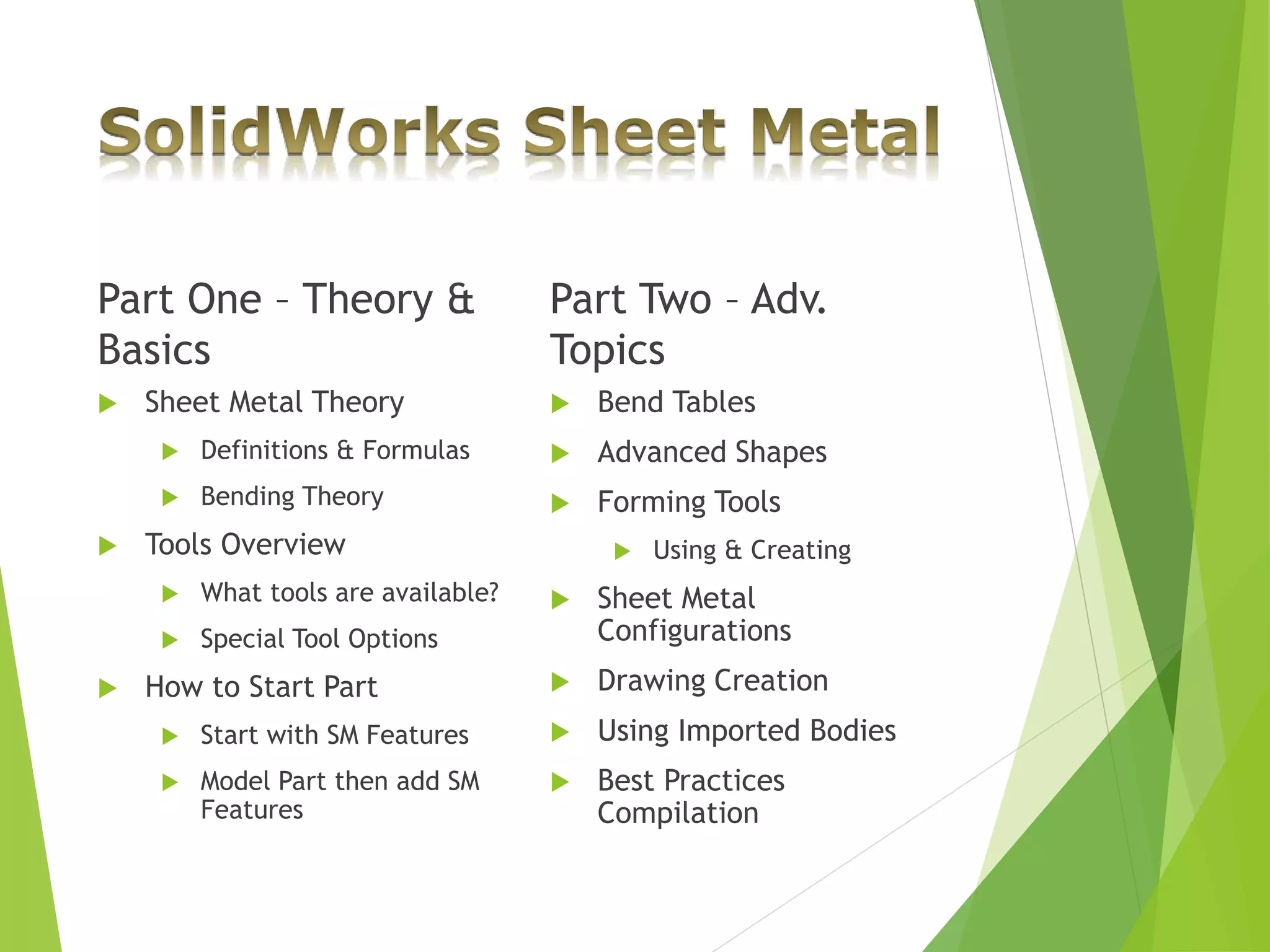
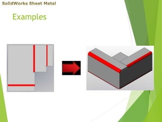
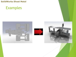
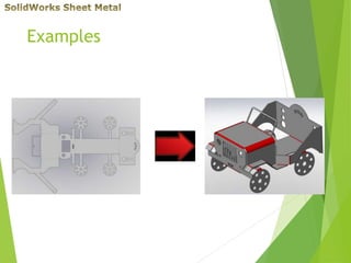
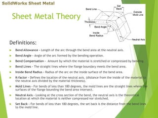
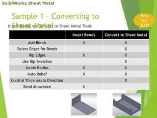
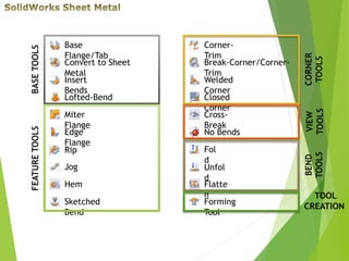
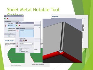
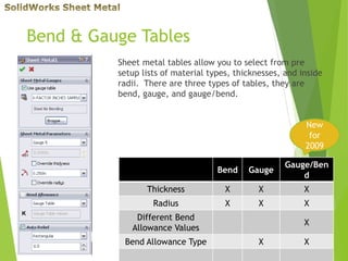
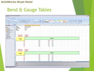
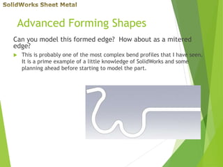
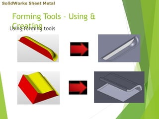
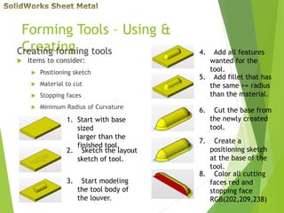
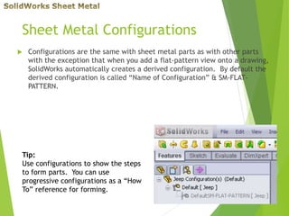
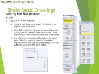
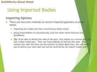

This document provides an overview of sheet metal modeling techniques in SolidWorks. It covers sheet metal theory, tools, bend and gauge tables, advanced forming shapes, creating forming tools, sheet metal configurations, drawings, and best practices for importing sheet metal parts. The document gives definitions and formulas for basic sheet metal features and walks through examples of modeling different sheet metal parts and features.


