Downloaded 2,221 times
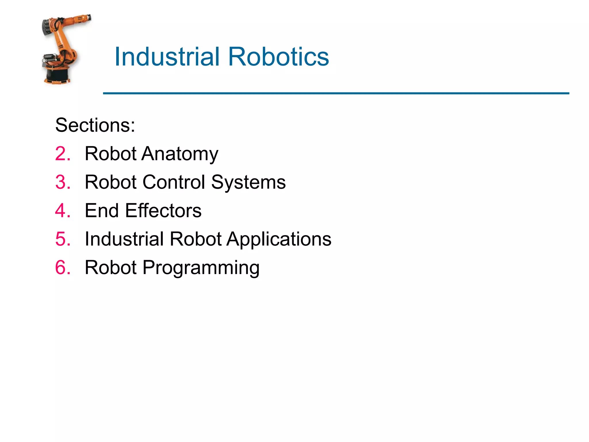


This document provides an overview of industrial robotics, including robot anatomy, control systems, end effectors, applications, and programming. It describes the typical components of a robot like links, joints, drives, and sensors. Common robot configurations and their joint notation are shown. The document also discusses robot programming methods including leadthrough and textual languages, as well as simulation for offline programming.
Overview of industrial robotics covering anatomy, control systems, end effectors, applications, and programming.
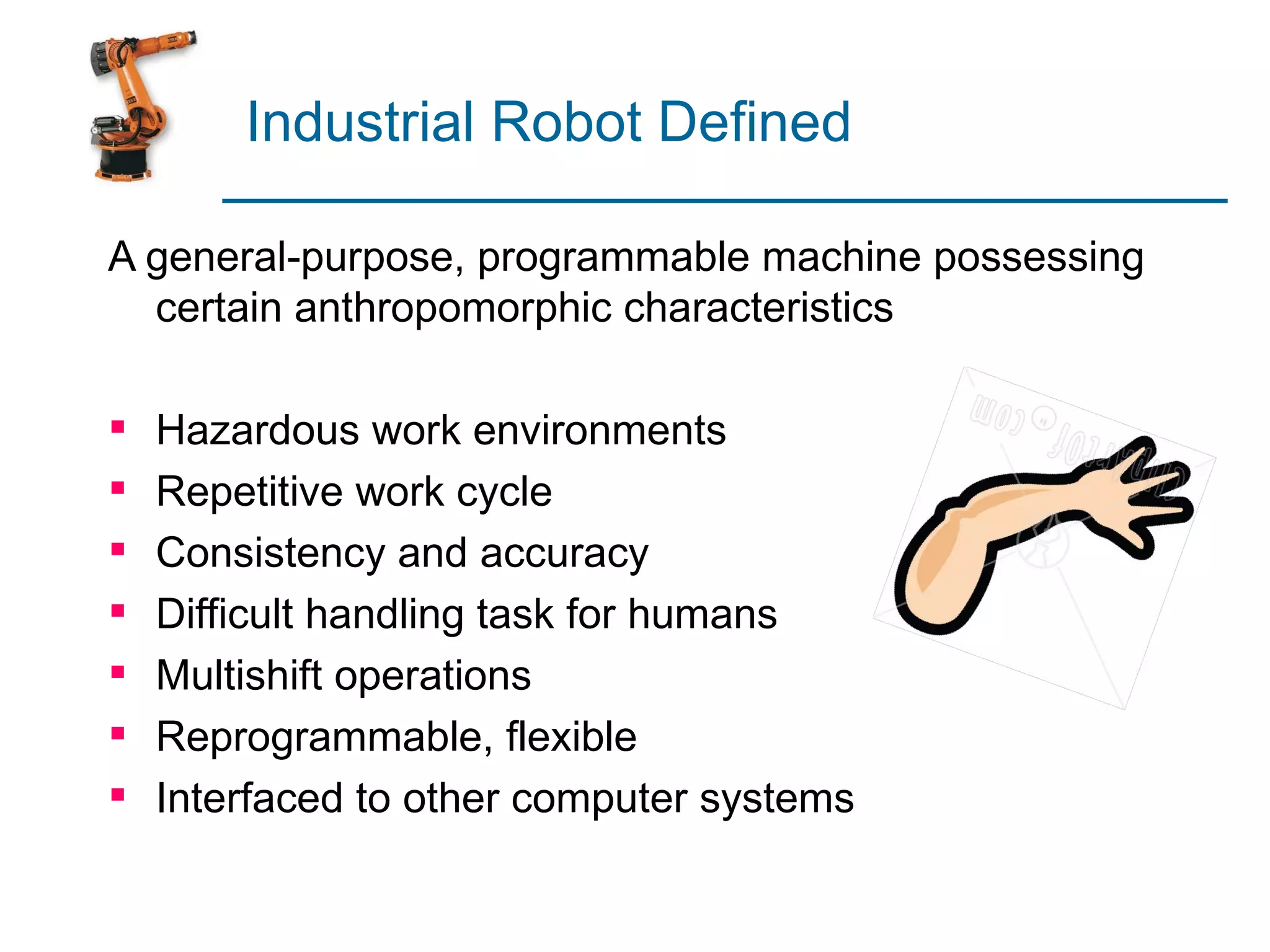
Definition highlighting features such as flexibility, accuracy, and suitability for hazardous environments.
Explains the manipulator structure, including joints and links, and the concept of degrees of freedom.
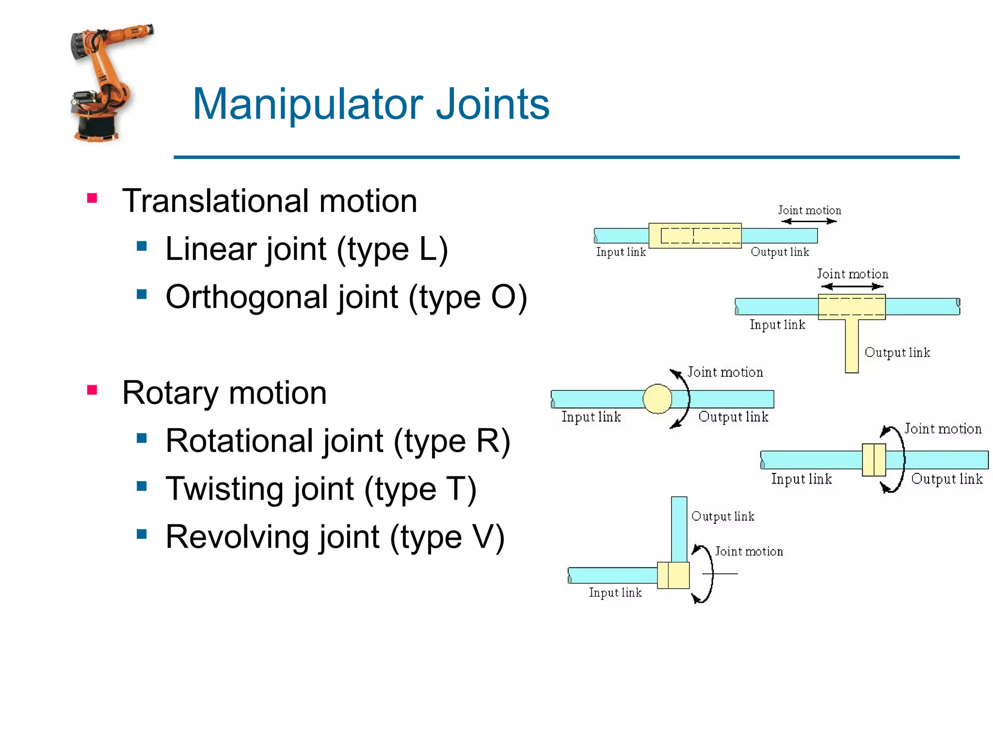
Details on joint motion types: translational and rotary, with various joint classifications.
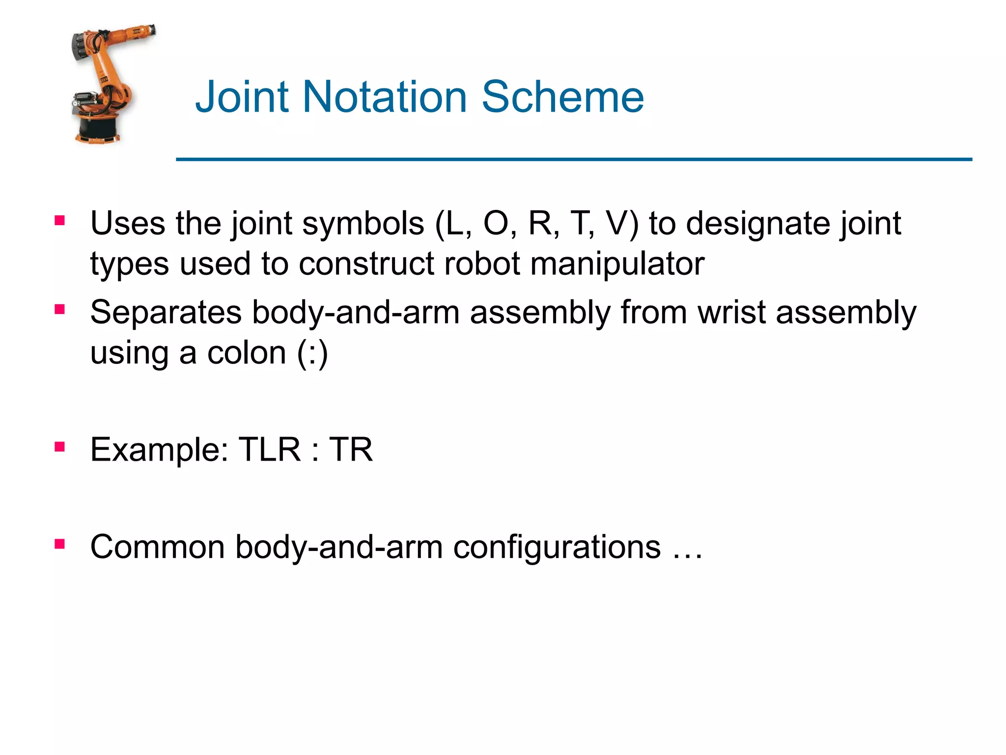
Discusses a notation system for specifying joint types in robotic manipulators.
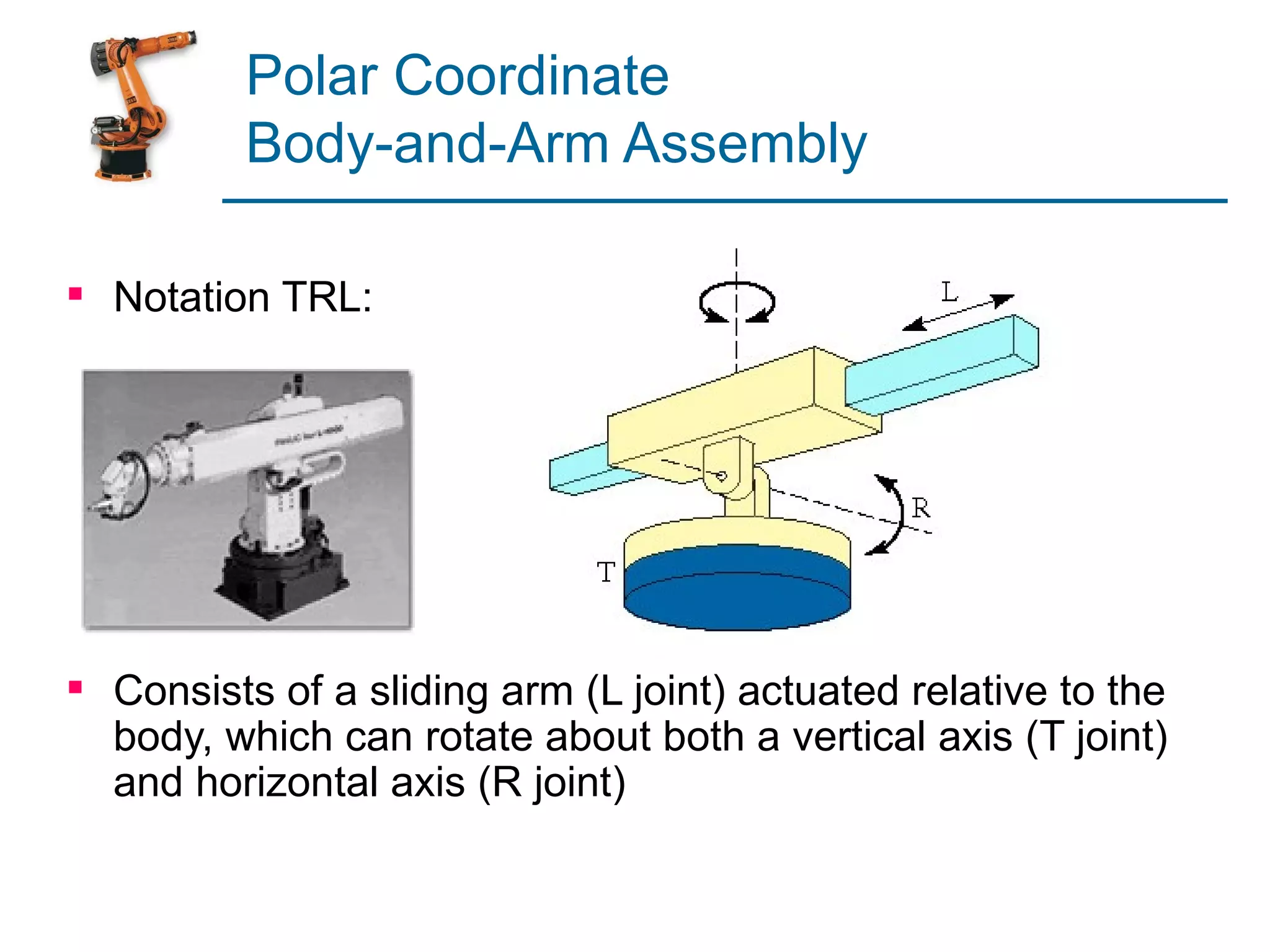
Description of polar coordinate assemblies and their structure using specific joint types.
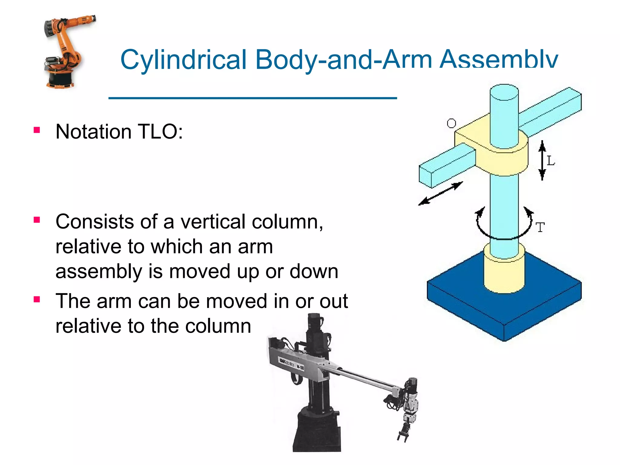
Outline of the cylindrical assembly design, detailing movement capabilities relative to a vertical column.
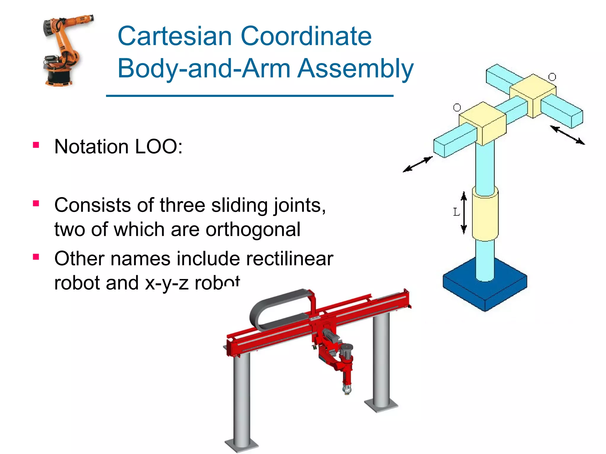
Explanation of Cartesian robot configurations with three sliding joints.
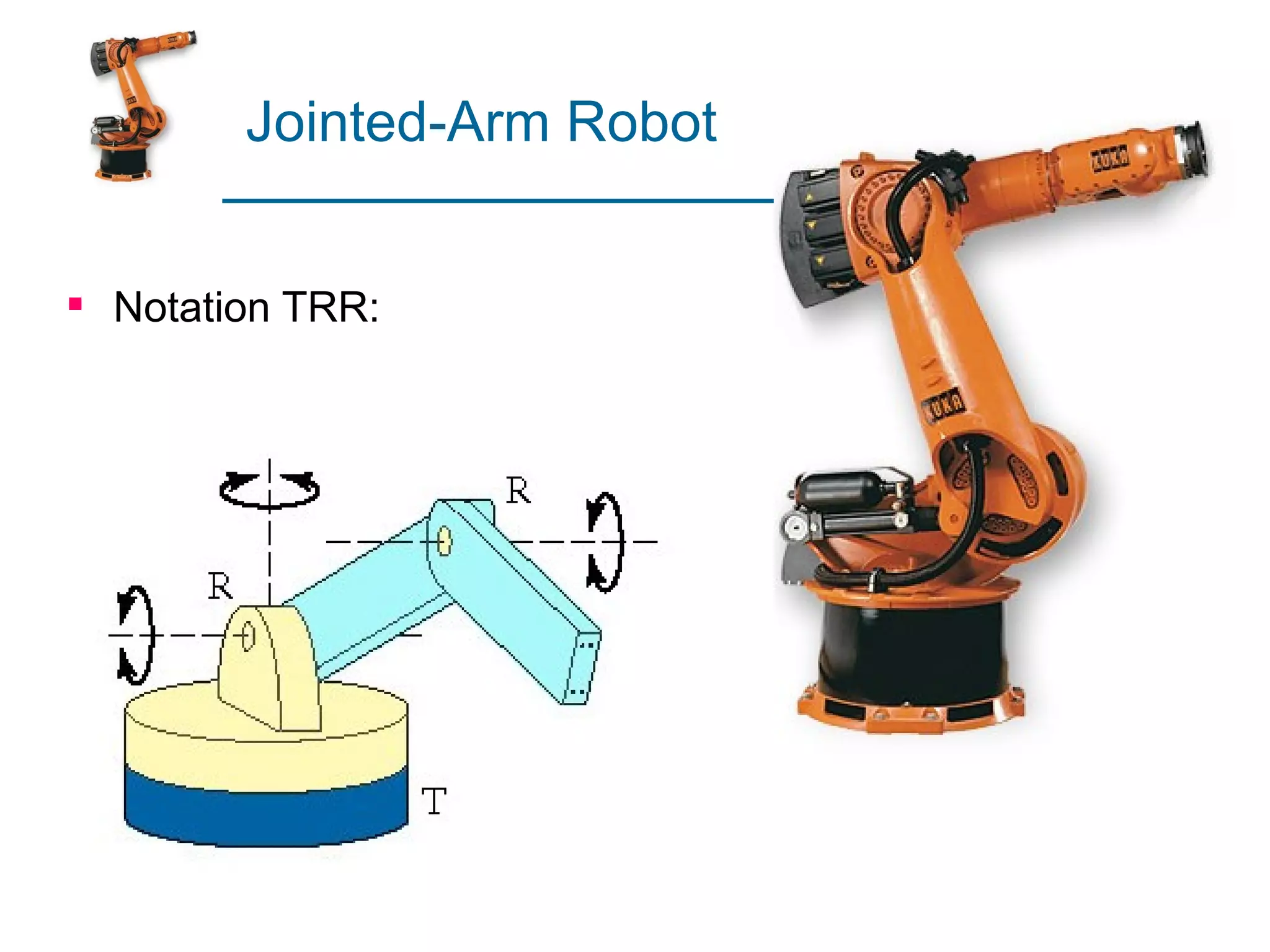
Notation describing the structure of a jointed-arm robot.
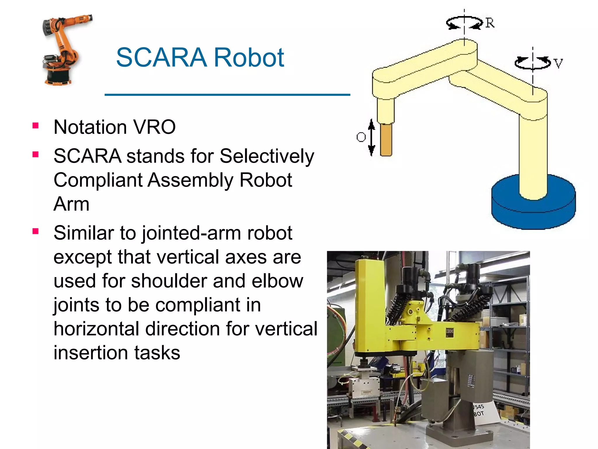
Overview of SCARA robots, designed for vertical insertion tasks with flexible joints.
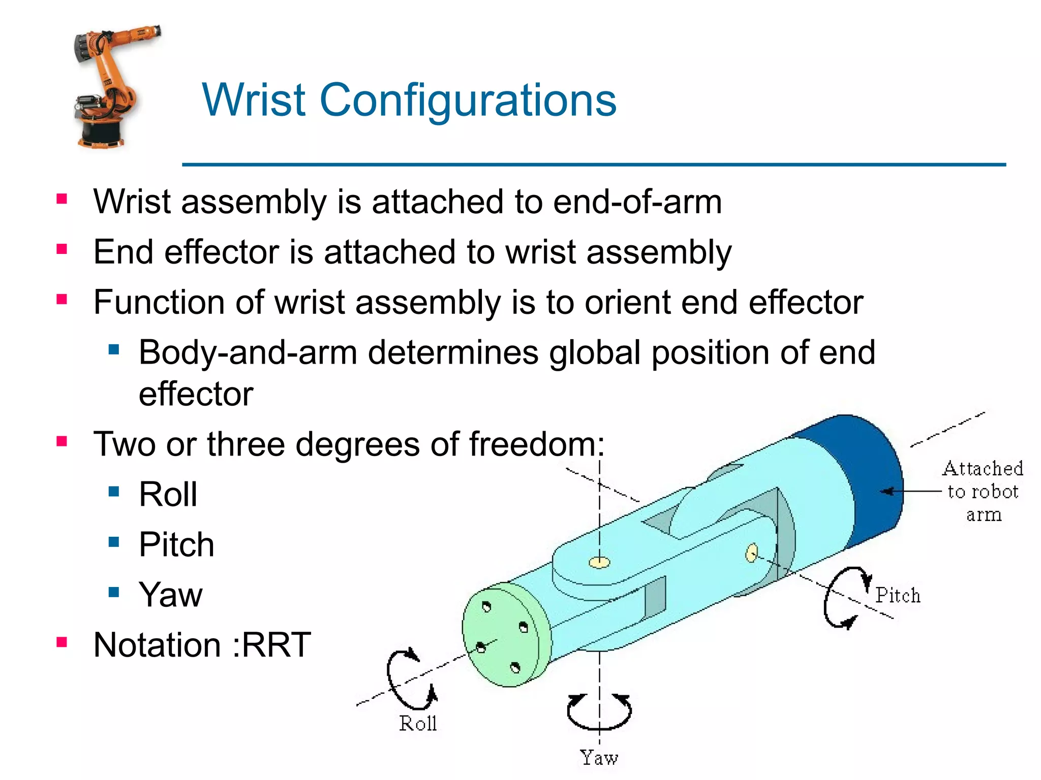
Describes how wrist assembly operates to orient end effectors with specific degrees of freedom.
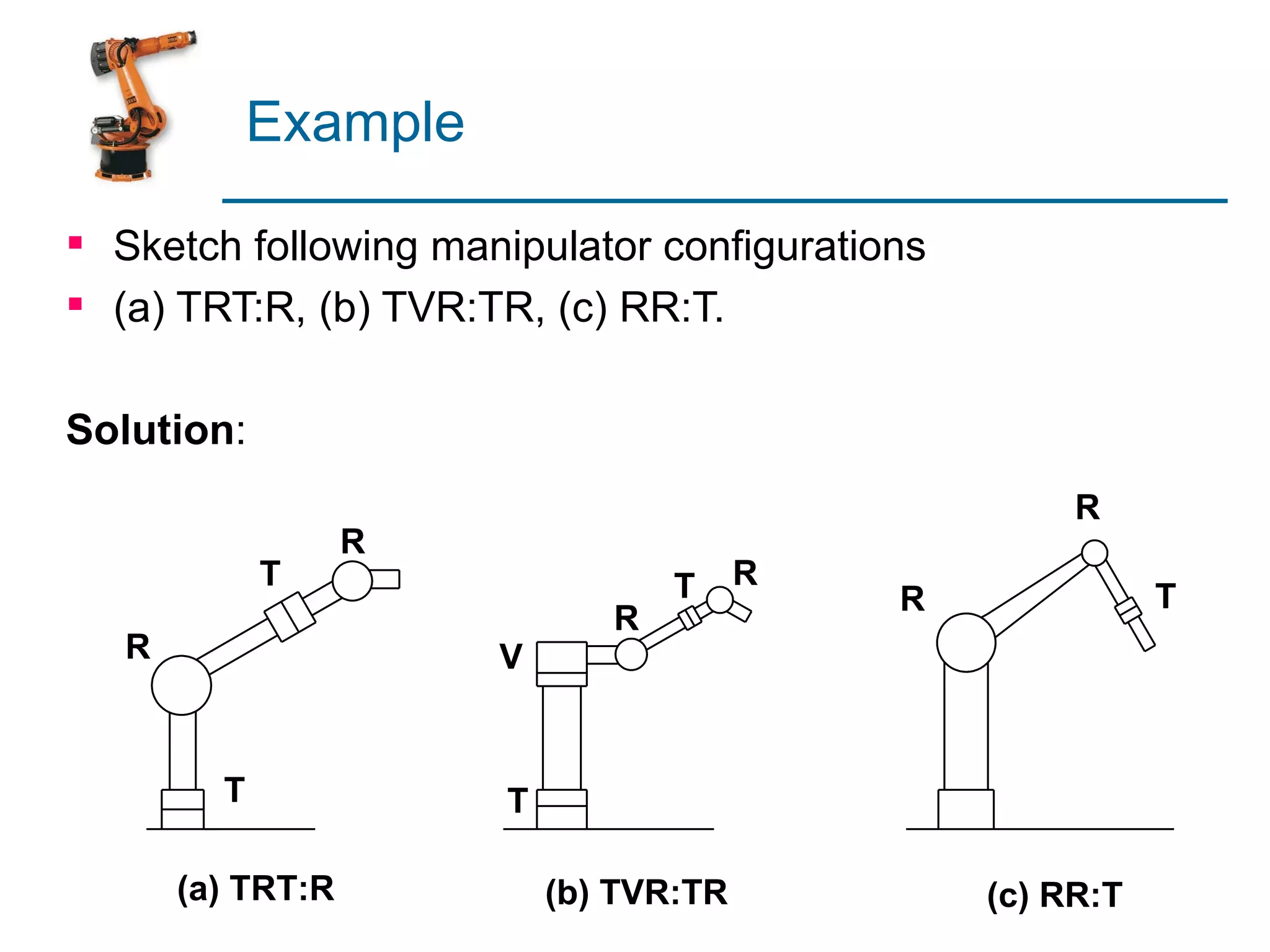
Visualization of various manipulator configurations based on joint notations.
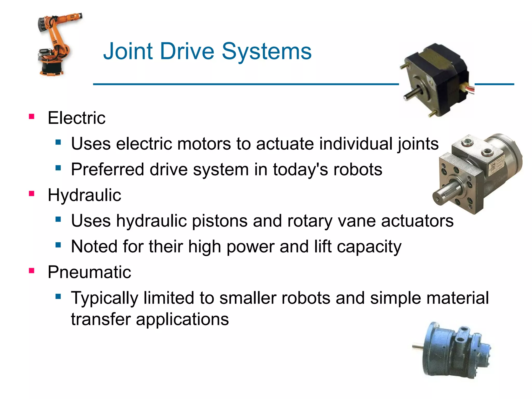
Highlights different joint drive systems: electric, hydraulic, and pneumatic.
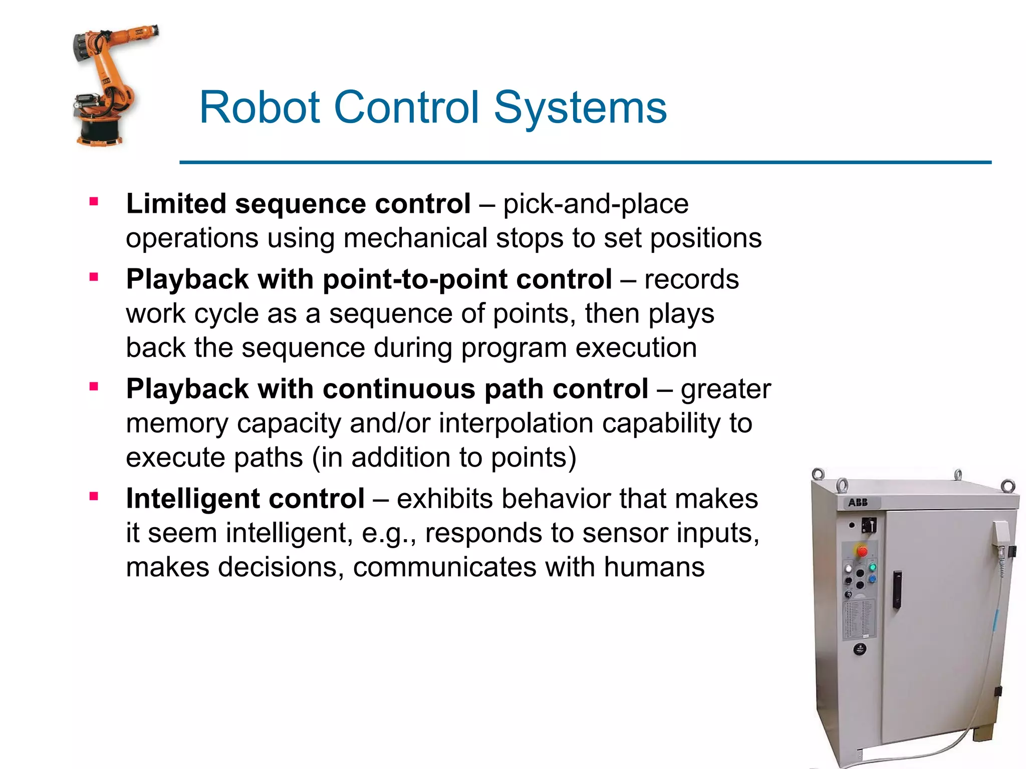
Various types of robot control including sequence control and intelligent control mechanisms.
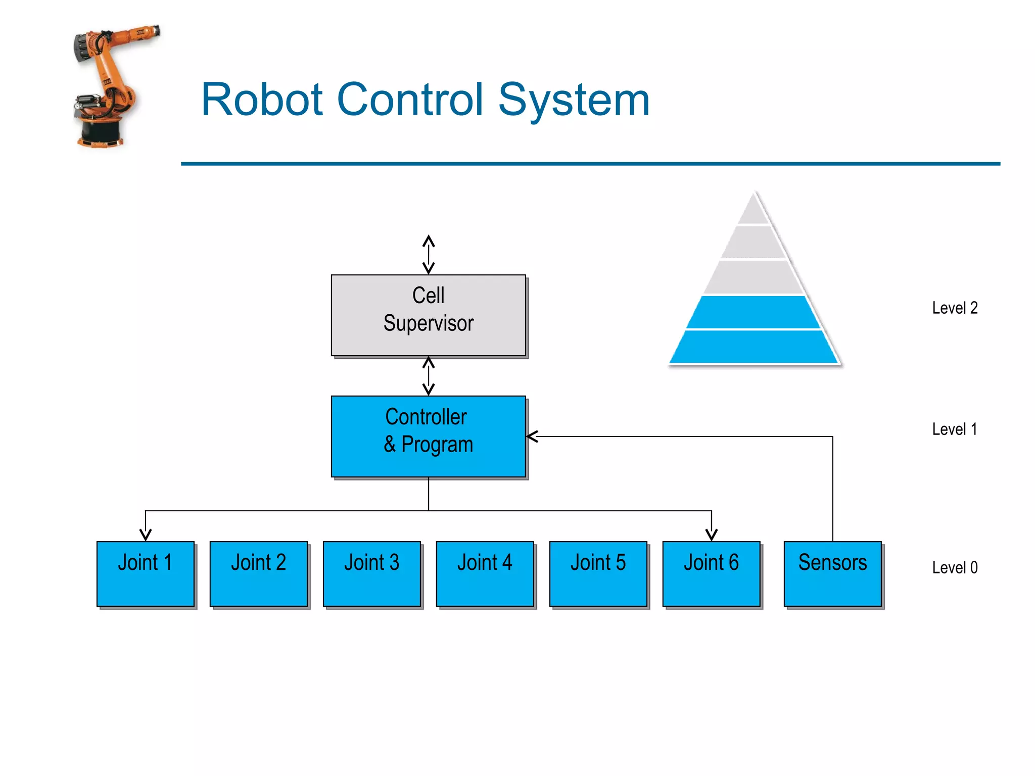
Illustration of a robotic control system structure with levels and sensors.
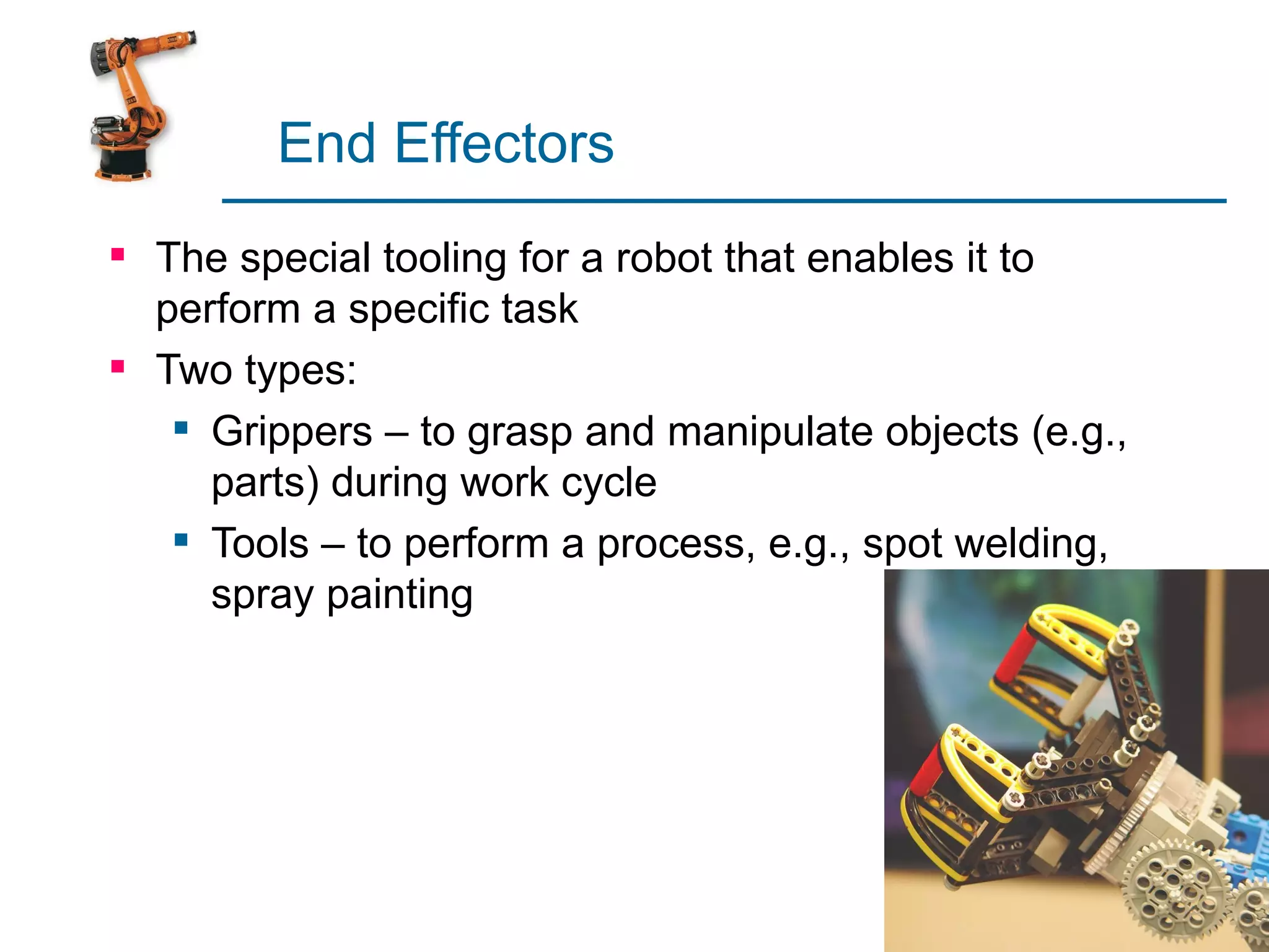
Describes special tooling (grippers and tools) that enables robots to perform specific tasks.
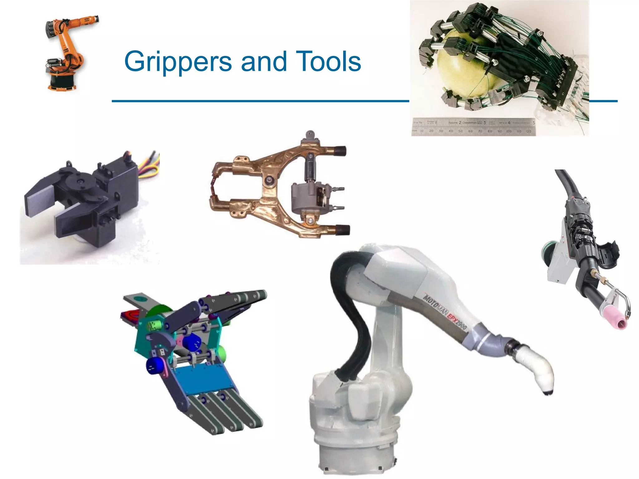
Details on various grippers and tools used in industrial robots.
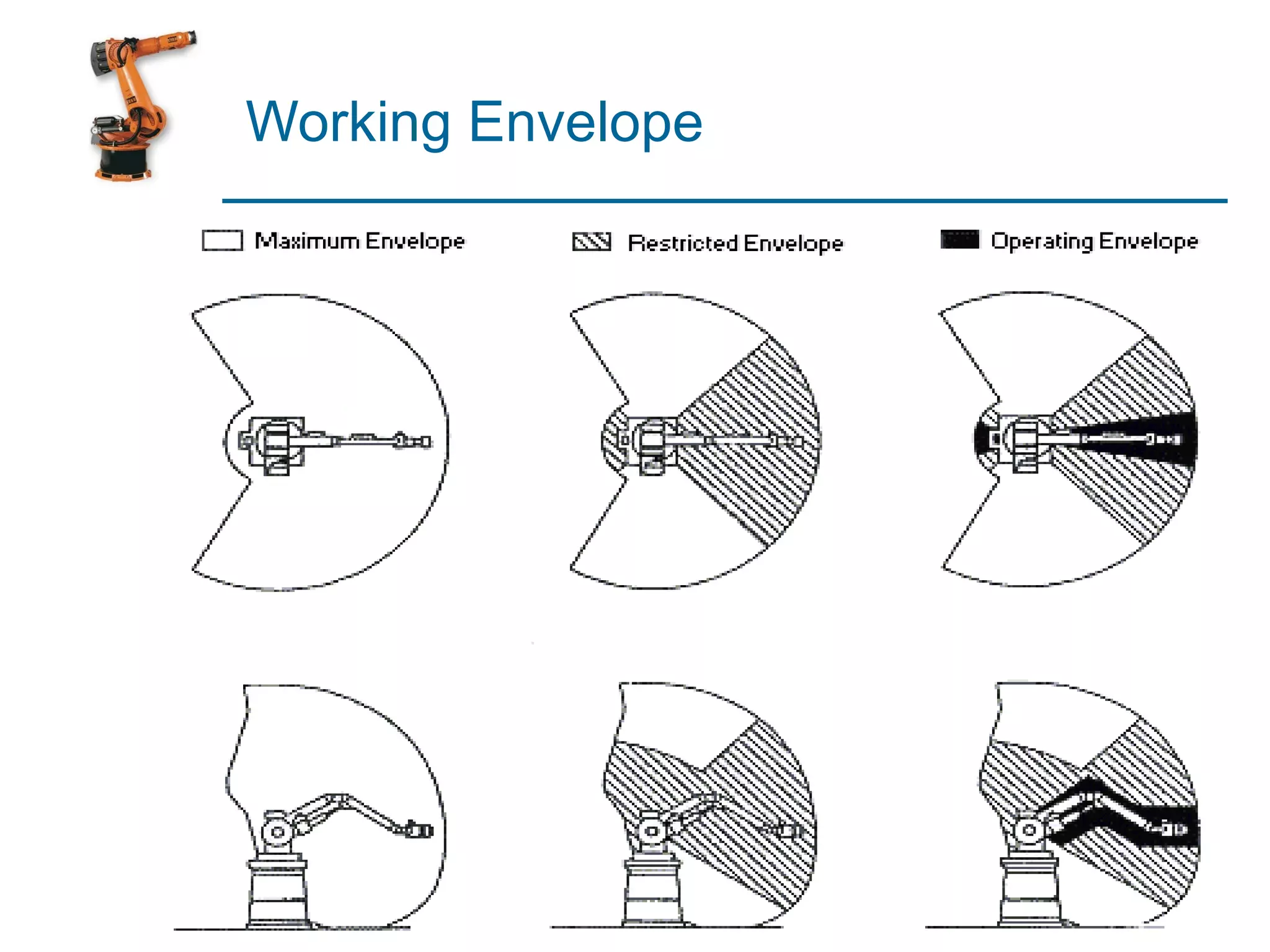
Concept of working envelope defining the operating range of a robot.
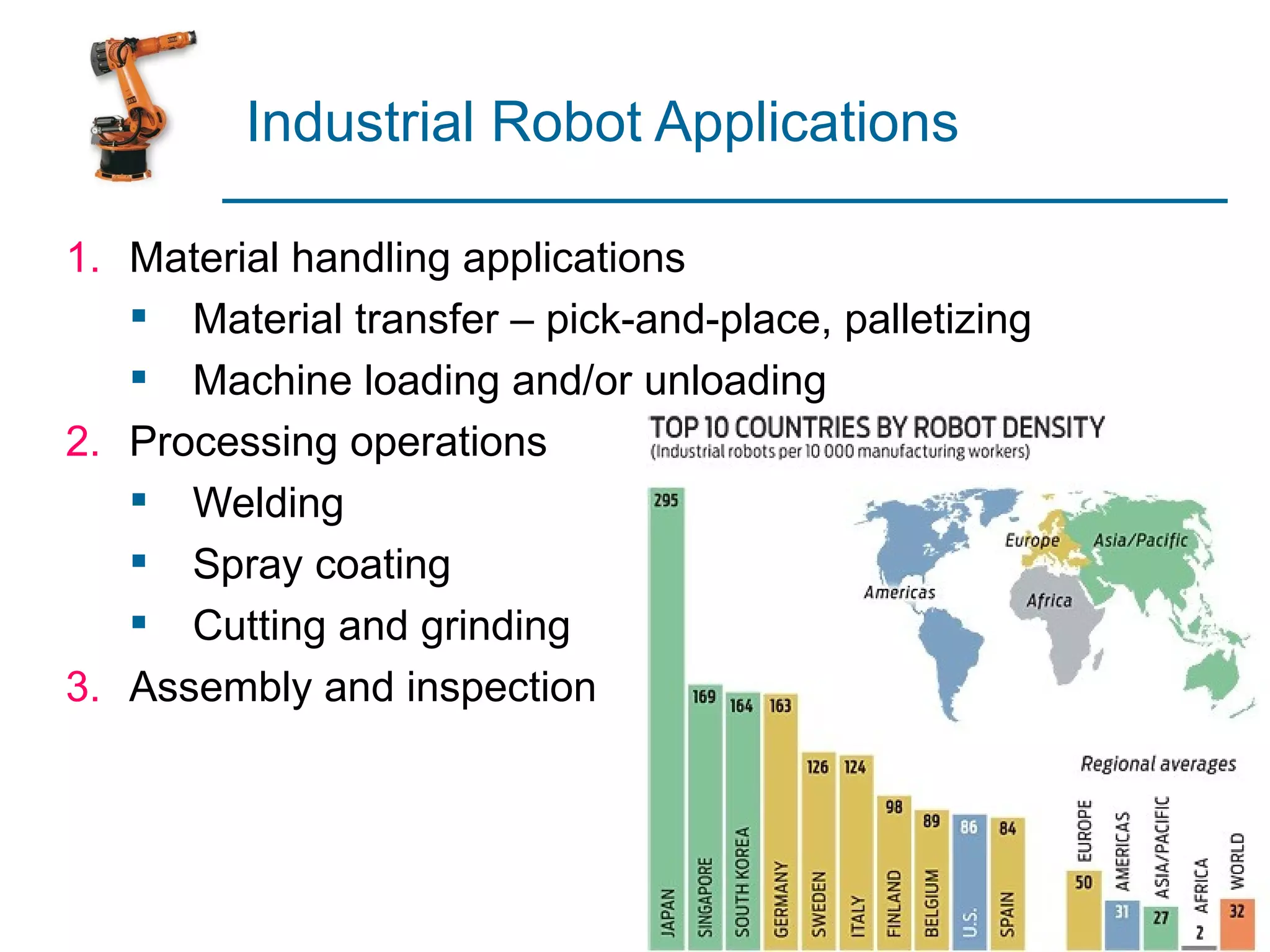
Diverse applications in material handling, processing, and assembly.
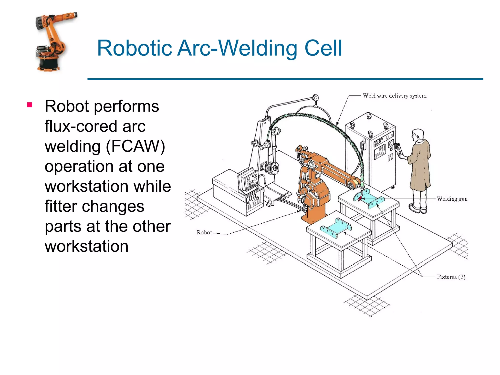
Illustrative example of a robotic arc-welding cell performing welding tasks.
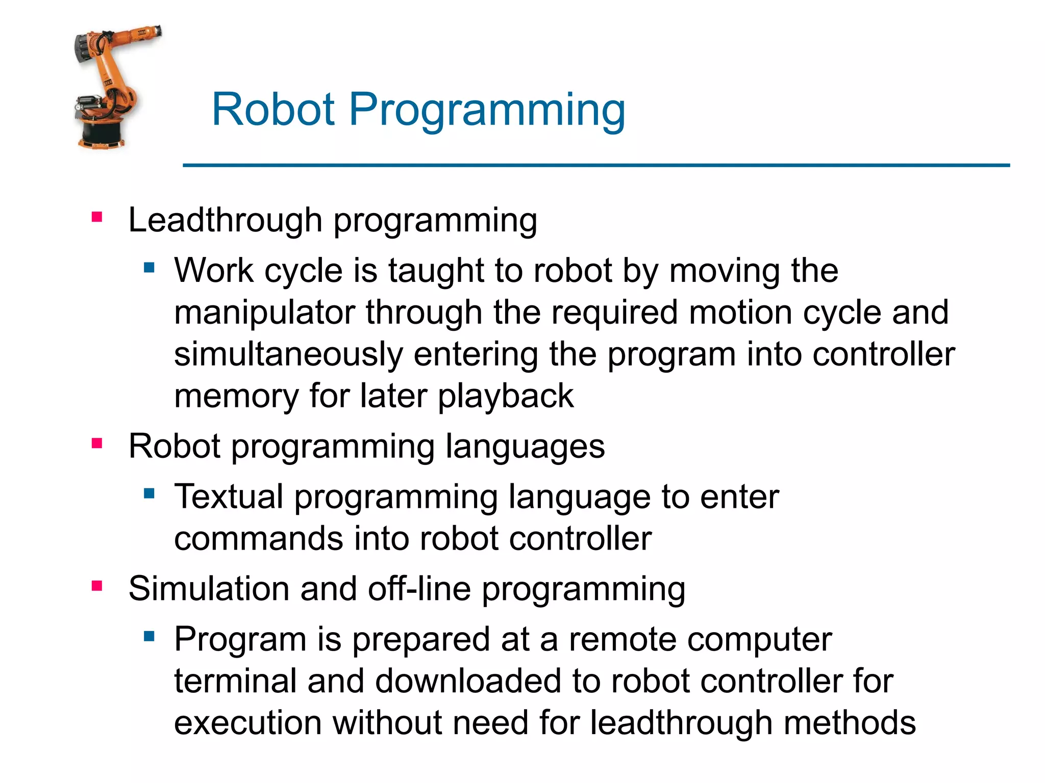
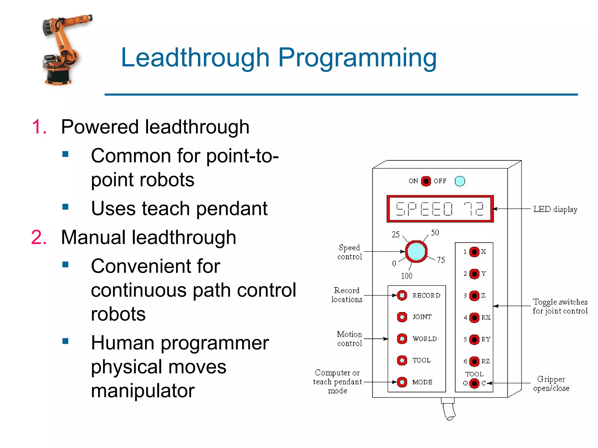
Overview of leadthrough programming and robot programming languages.
Different leadthrough methods including powered and manual programming.
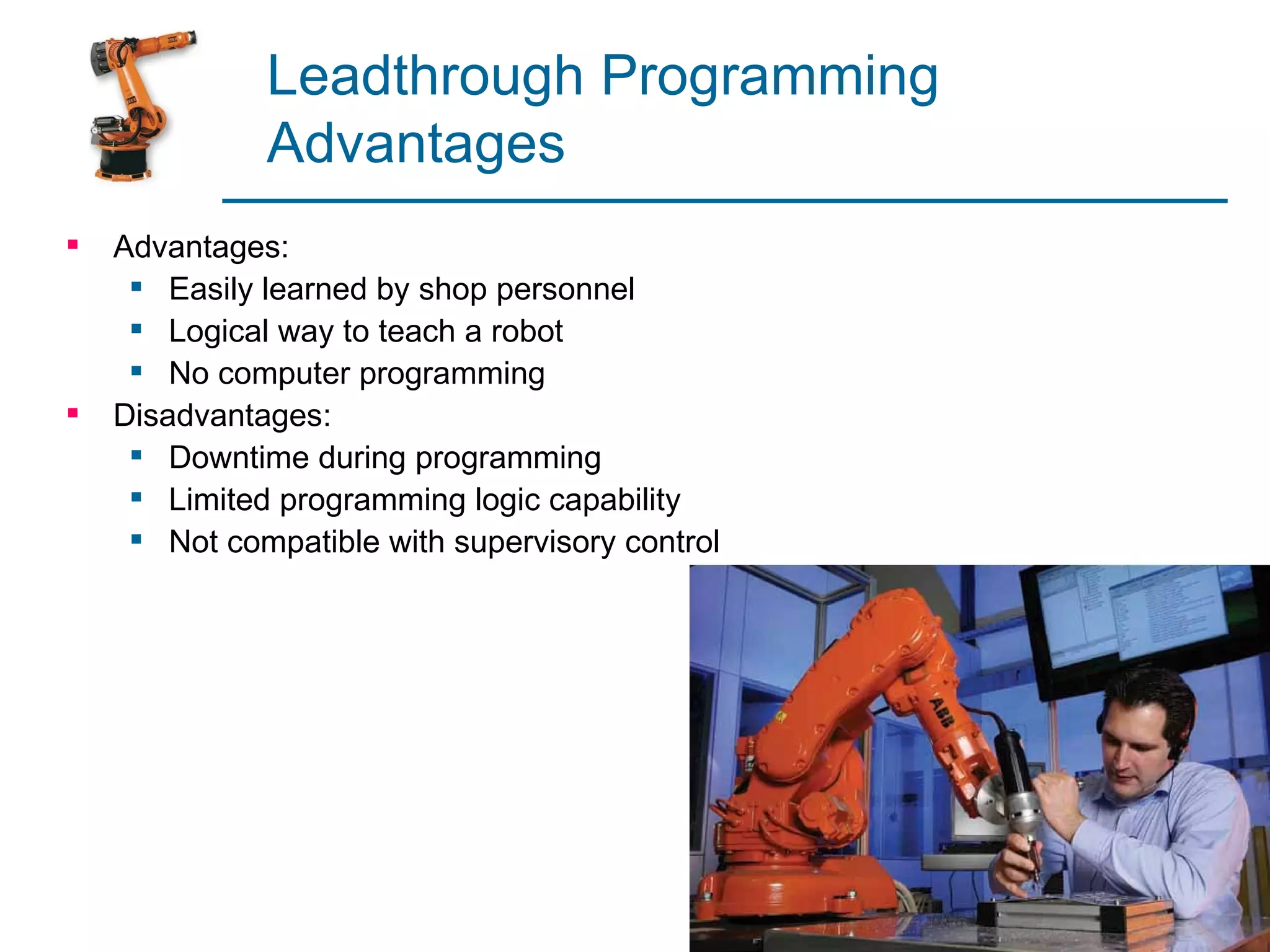
Pros and cons of leadthrough programming, including ease of use and downtime considerations.
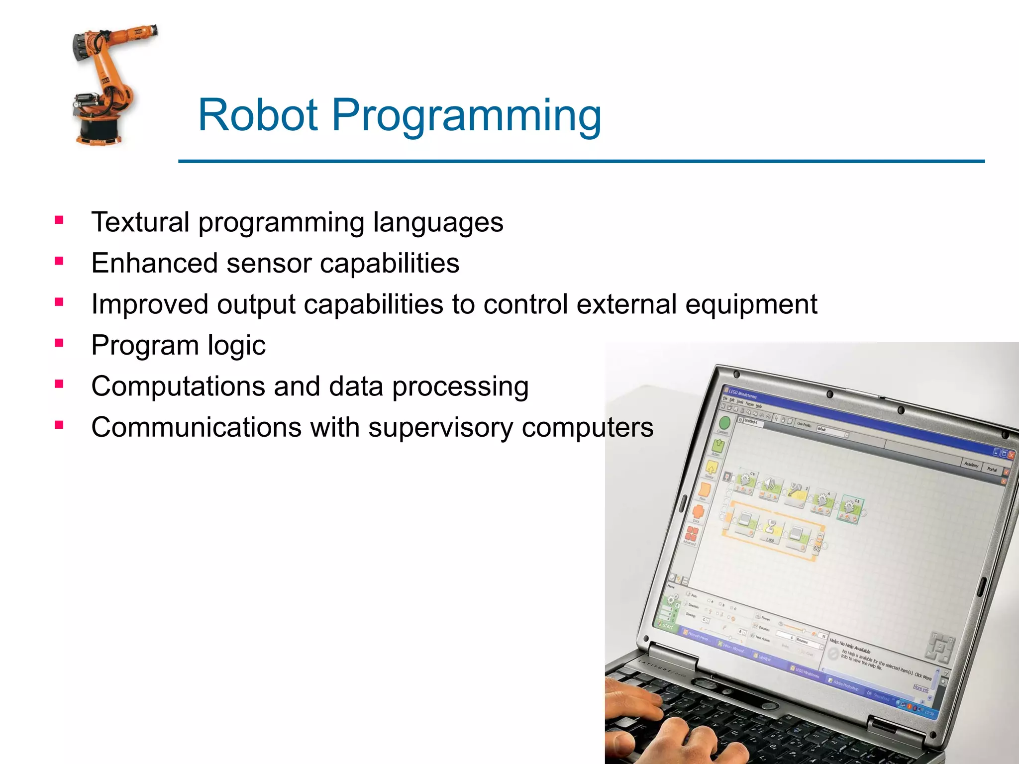
Overview of textural programming languages and enhanced robot capabilities.
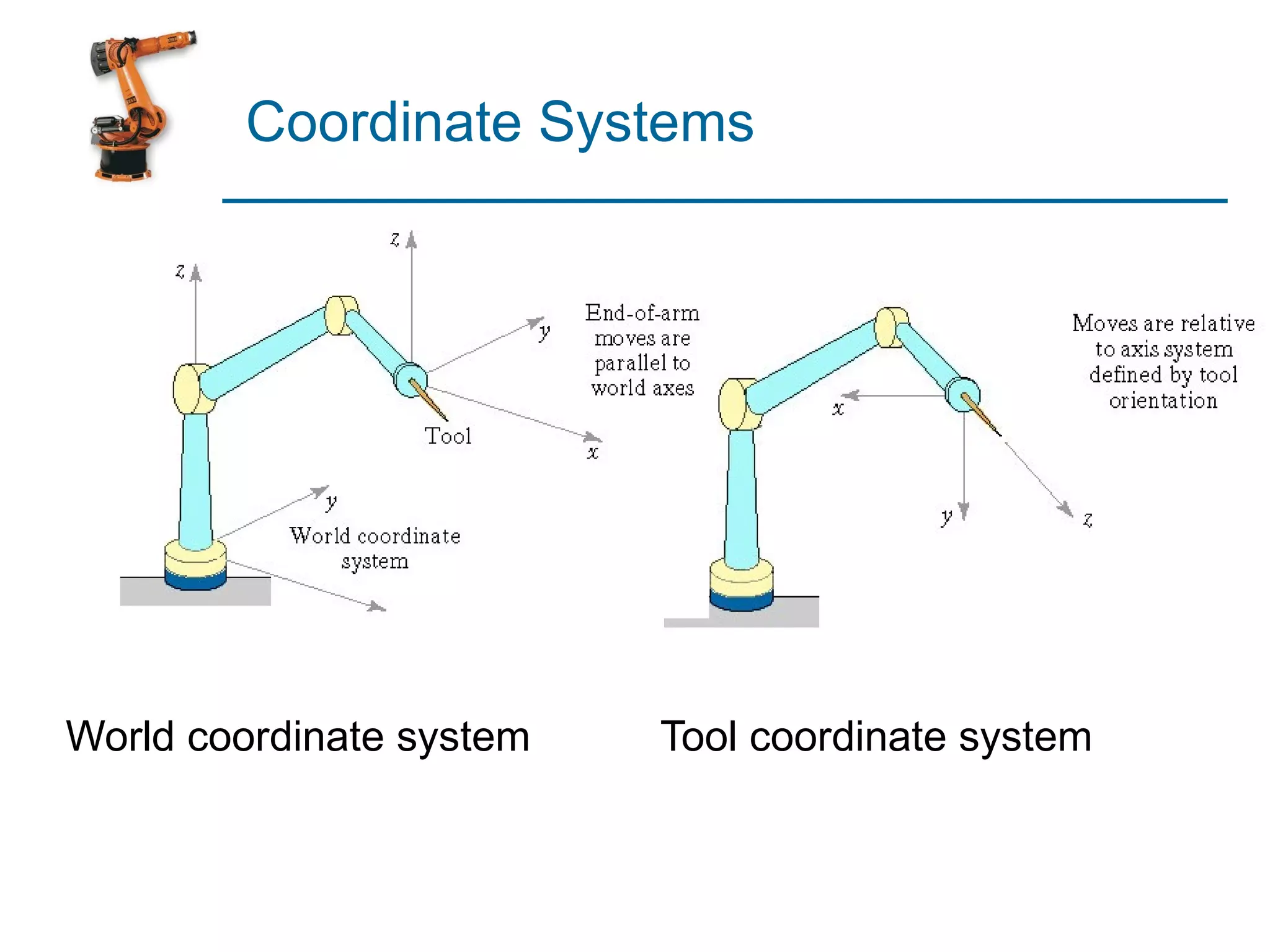
Introduction to world and tool coordinate systems in robotics.
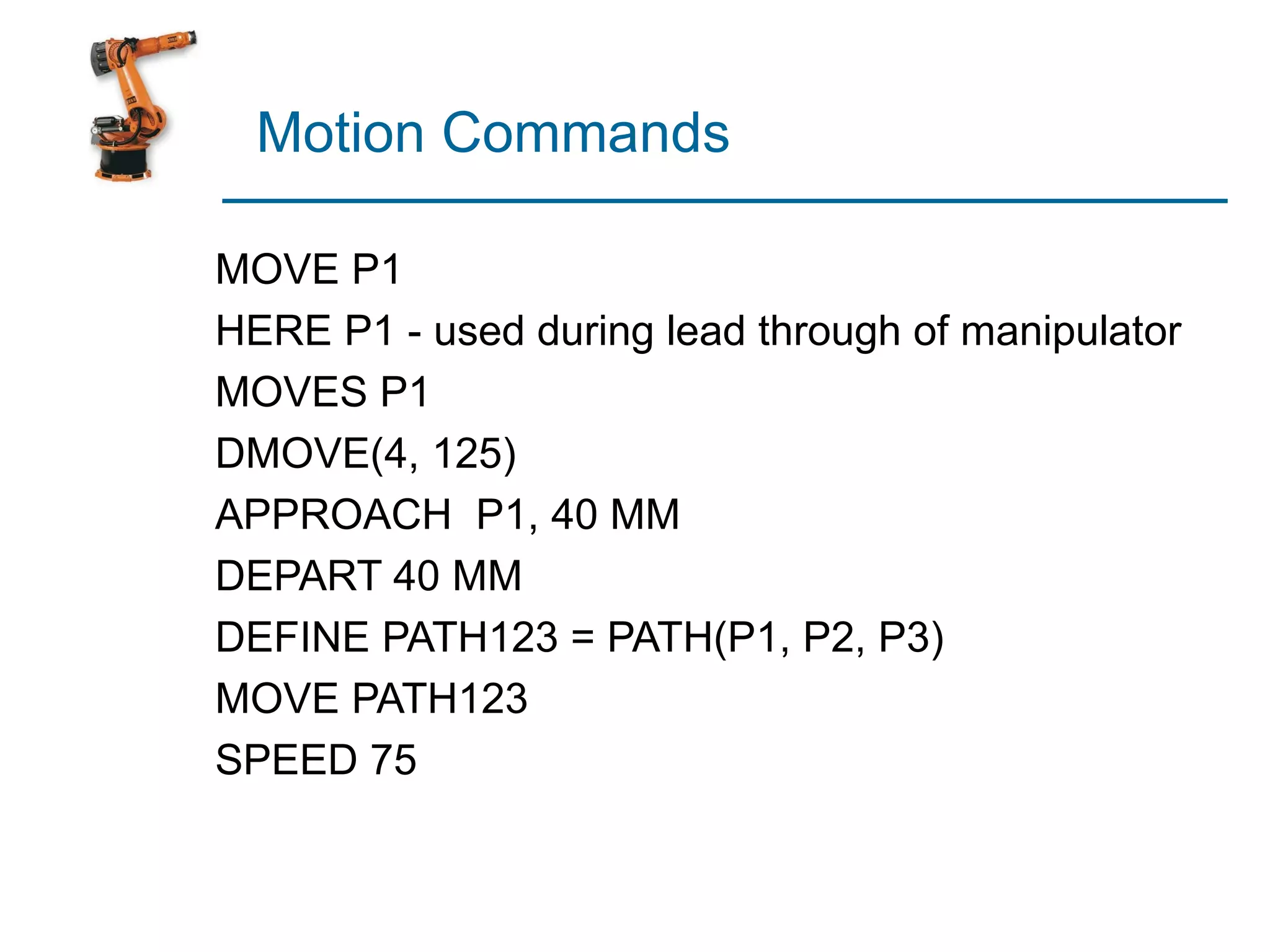
Examples of motion commands used in leadthrough programming contexts.
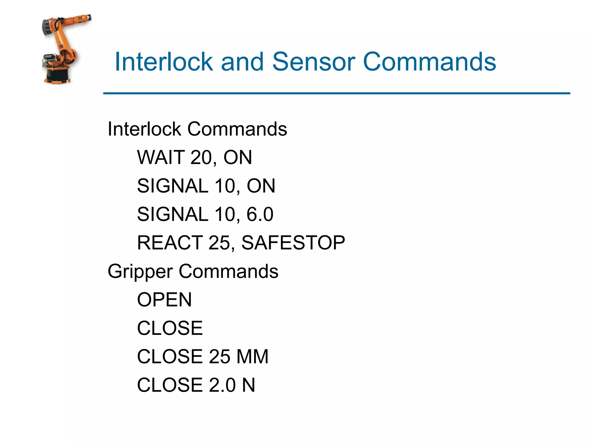
Examples of interlock and gripper commands used in robot operations.
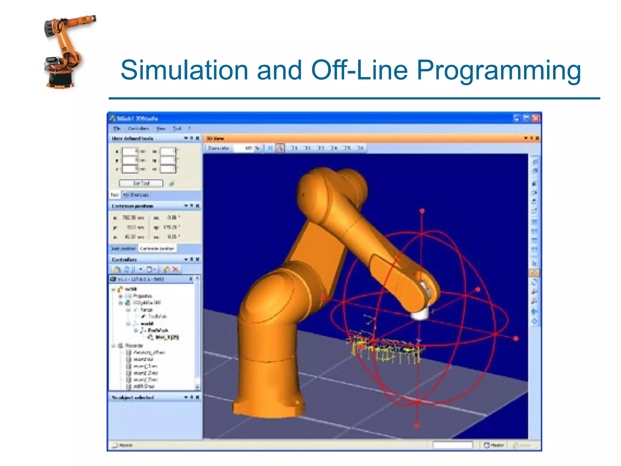
Introduction to simulation and offline programming methods.
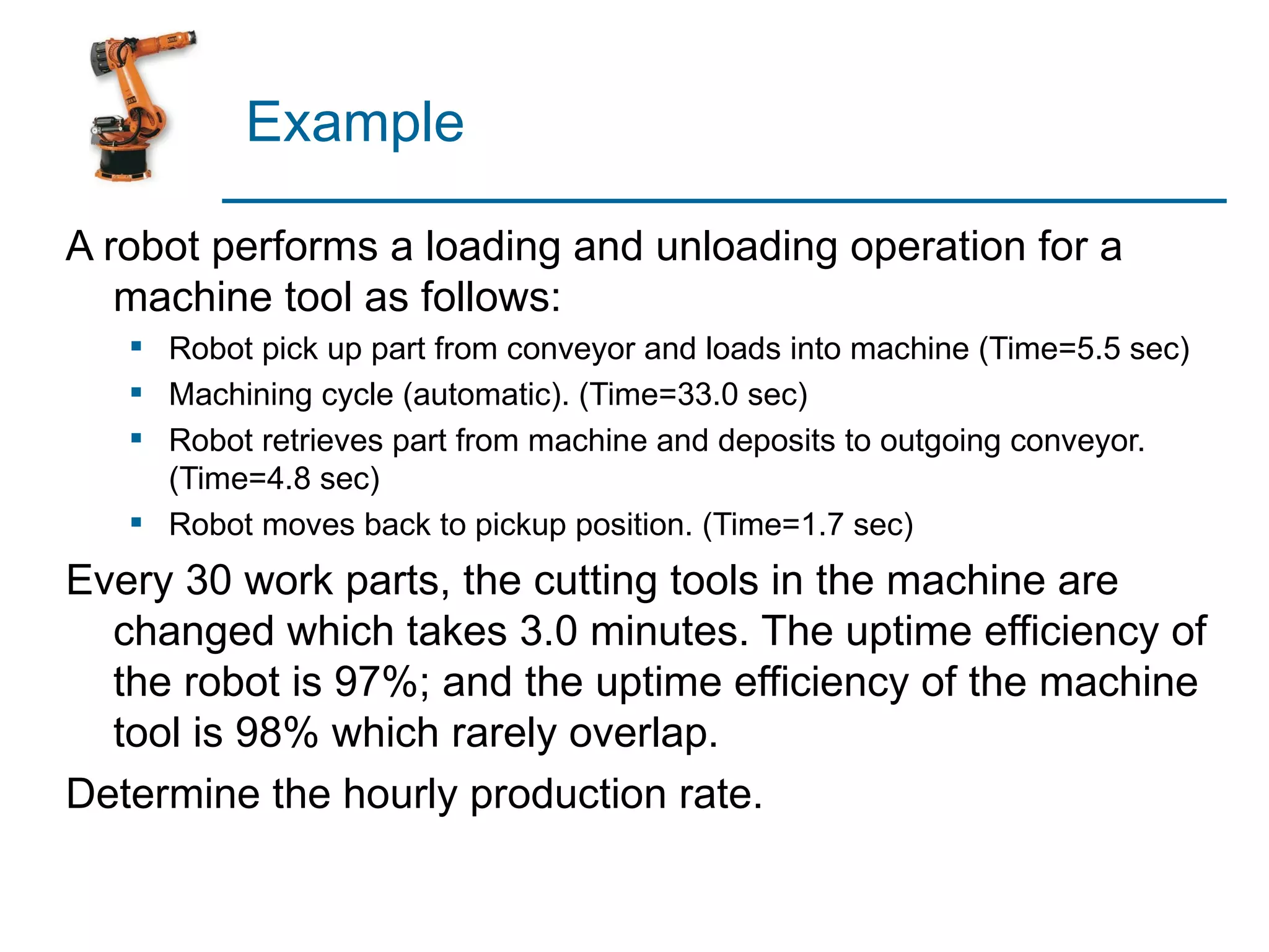
Detailed breakdown of a loading and unloading robotic operation with time calculations.
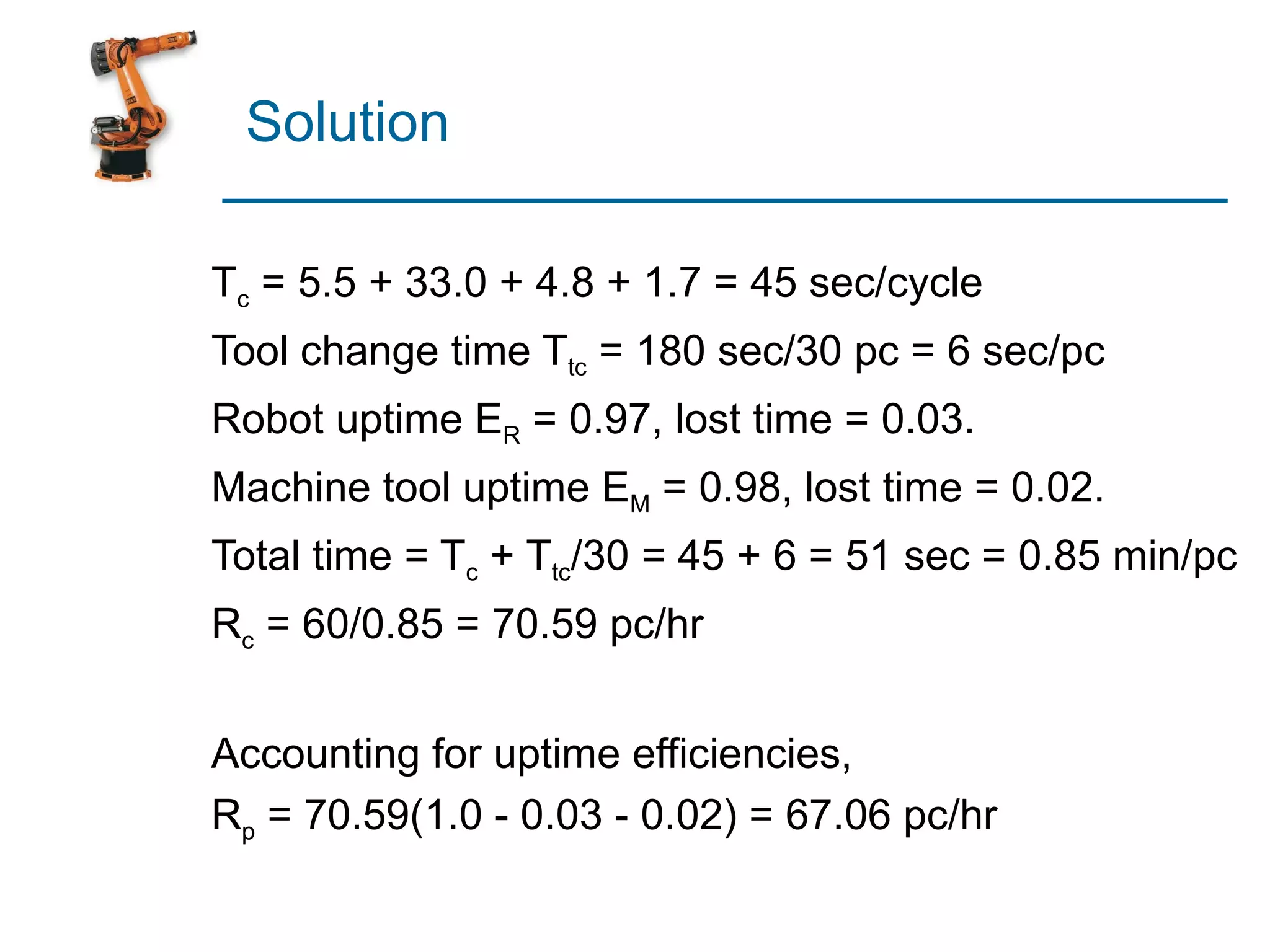
Calculation example to determine the production rate based on operational timing and efficiencies.