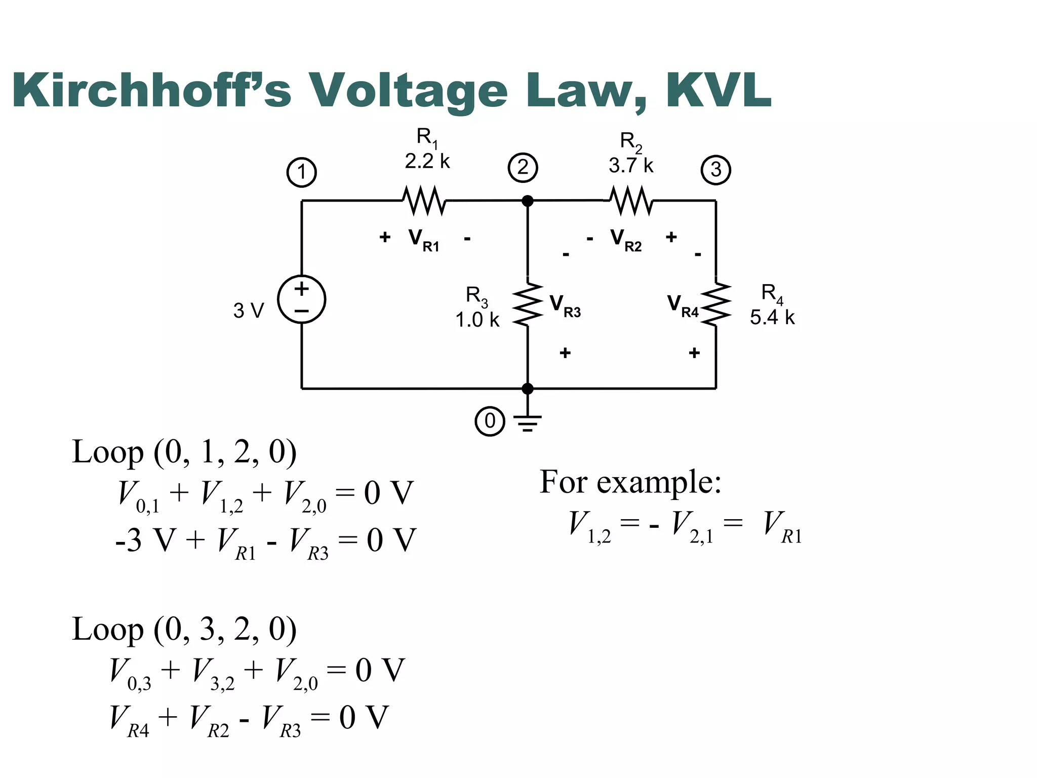
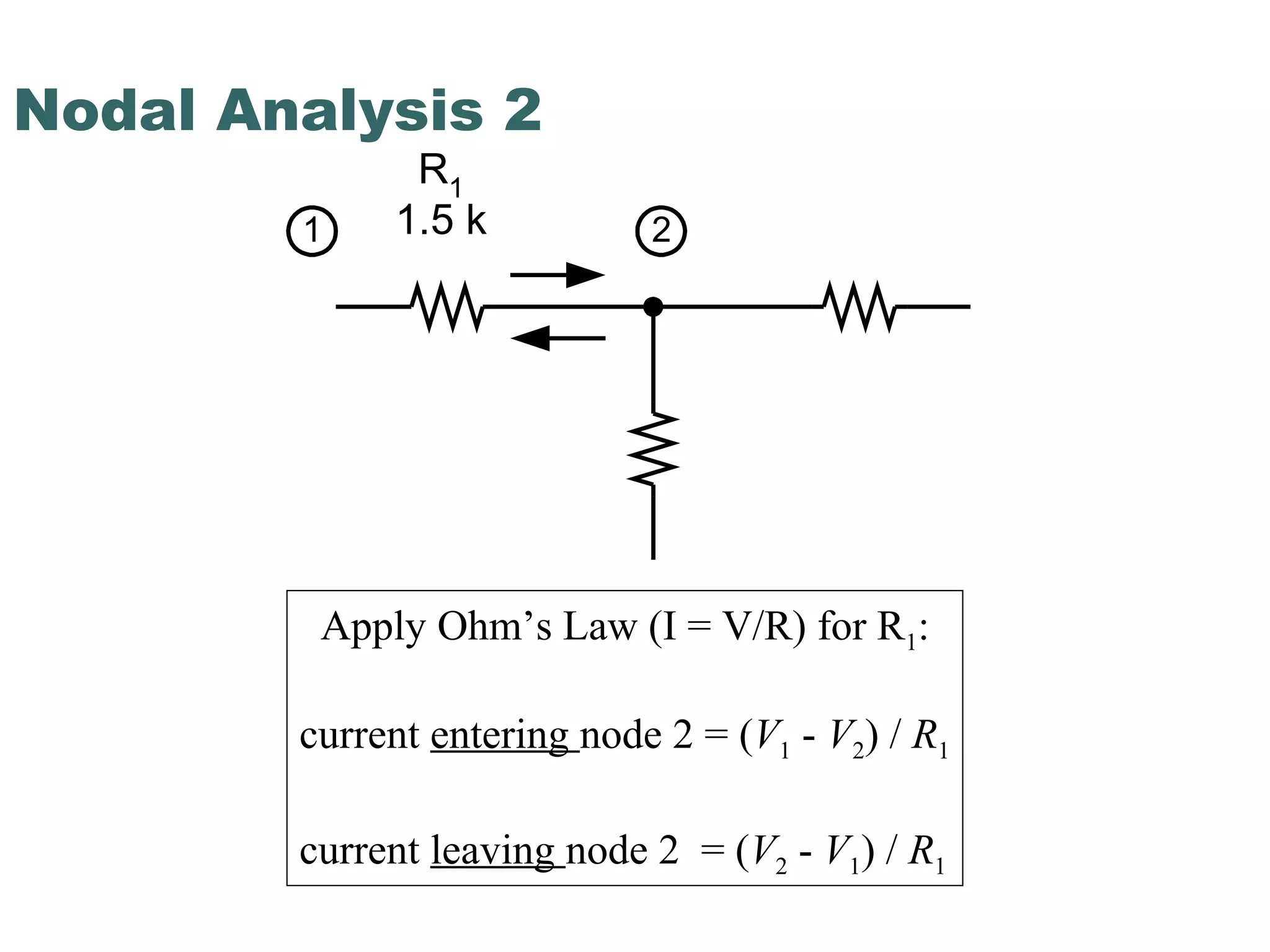
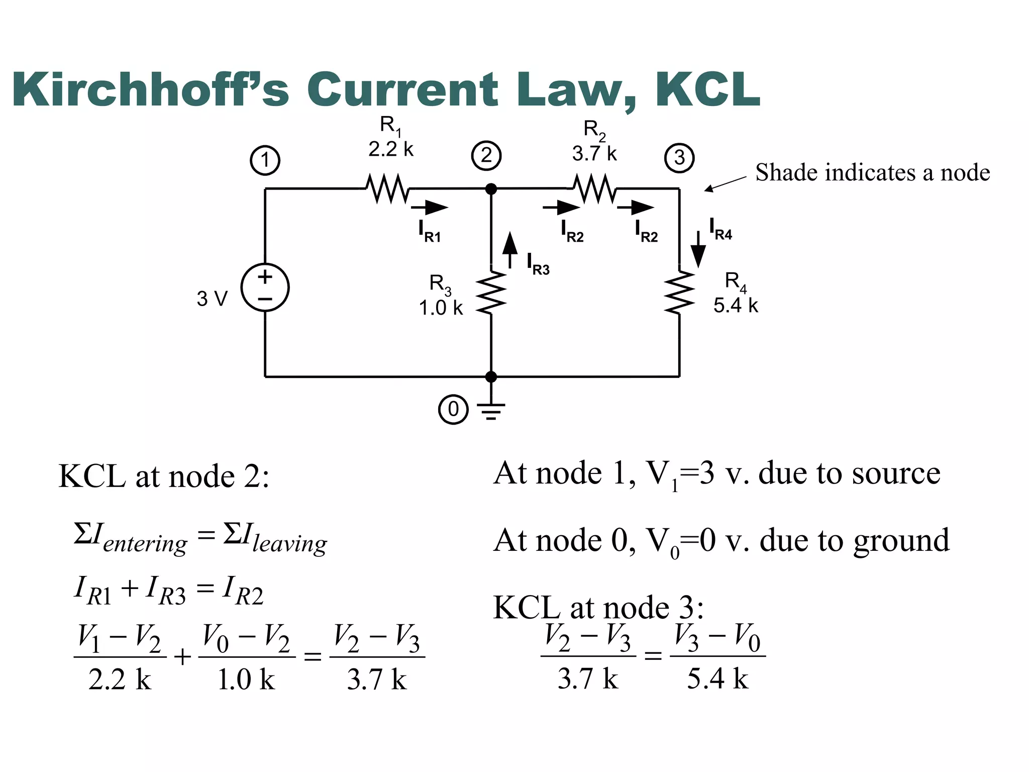
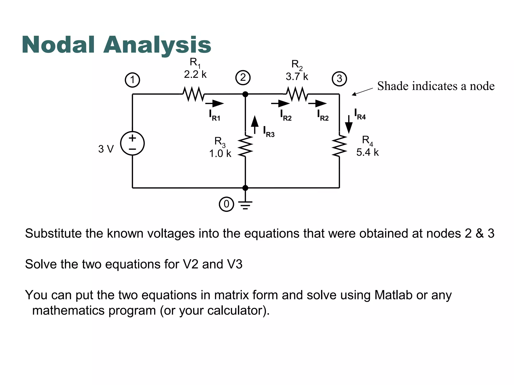
Nodal analysis
Multisim Window
R1
R2
R3
c a
b
c a
b
Rc
Ra
Rb
Delta or ∆ Wye or Y
R
R R
R R R
R
R R
R R R
R
R R
R R R
a
b
c
=
+ +
=
+ +
=
+ +
1 2
1 2 3
2 3
1 2 3
1 3
1 2 3
Wye-Delta Transformation
R
R R R R R R
R
R
R R R R R R
R
R
R R R R R R
R
a b b c a c
b
a b b c a c
c
a b b c a c
a
1
2
3
=
+ +
=
+ +
=
+ +
Y to Δ Equations Δ to Y
Kirchhoff’s Voltage Law, KVL
3 V
R1
2.2 k
R2
3.7 k
R4
5.4 k
R3
1.0 k
1 2 3
0
+ VR1
- - VR2
+
-
VR4
+
-
VR3
+
Loop (0, 1, 2, 0)
V0,1 + V1,2 + V2,0 = 0 V
-3 V + VR1 - VR3 = 0 V
Loop (0, 3, 2, 0)
V0,3 + V3,2 + V2,0 = 0 V
VR4 + VR2 - VR3 = 0 V
For example:
V1,2 = - V2,1 = VR1
Nodal Analysis 1
entering
leaving
A current is entering the node if the current is leaving the device.
A current is leaving the node if the current is entering the device.
Nodal Analysis 2
Apply Ohm’s Law (I = V/R) for R1:
current entering node 2 = (V1 - V2) / R1
current leaving node 2 = (V2 - V1) / R1
R1
1.5 k1 2
Kirchhoff’s Current Law, KCL
KCL at node 2:
Σ ΣI I
I I I
V V V V V V
entering leaving
R R R
=
+ =
−
+
−
=
−
1 3 2
1 2 0 2 2 3
2 2 1 3. k .0 k .7 k
Shade indicates a node
At node 1, V1=3 v. due to source
At node 0, V0=0 v. due to ground
KCL at node 3:
V V V V2 3 3 0
3 7
−
=
−
. k 5.4 k
3 V
R1
2.2 k
R2
3.7 k
R4
5.4 k
R3
1.0 k
1 2 3
0
IR1
IR2
IR3
IR2
IR4
Nodal Analysis
Shade indicates a node
3 V
R1
2.2 k
R2
3.7 k
R4
5.4 k
R3
1.0 k
1 2 3
0
IR1
IR2
IR3
IR2
IR4
Substitute the known voltages into the equations that were obtained at nodes 2 & 3
Solve the two equations for V2 and V3
You can put the two equations in matrix form and solve using Matlab or any
mathematics program (or your calculator).

kvl kcl- nodal analysis

  • 1.
  • 2.
  • 3.
    R1 R2 R3 c a b c a b Rc Ra Rb Deltaor ∆ Wye or Y R R R R R R R R R R R R R R R R R R a b c = + + = + + = + + 1 2 1 2 3 2 3 1 2 3 1 3 1 2 3 Wye-Delta Transformation R R R R R R R R R R R R R R R R R R R R R R R R a b b c a c b a b b c a c c a b b c a c a 1 2 3 = + + = + + = + + Y to Δ Equations Δ to Y
  • 4.
    Kirchhoff’s Voltage Law,KVL 3 V R1 2.2 k R2 3.7 k R4 5.4 k R3 1.0 k 1 2 3 0 + VR1 - - VR2 + - VR4 + - VR3 + Loop (0, 1, 2, 0) V0,1 + V1,2 + V2,0 = 0 V -3 V + VR1 - VR3 = 0 V Loop (0, 3, 2, 0) V0,3 + V3,2 + V2,0 = 0 V VR4 + VR2 - VR3 = 0 V For example: V1,2 = - V2,1 = VR1
  • 5.
    Nodal Analysis 1 entering leaving Acurrent is entering the node if the current is leaving the device. A current is leaving the node if the current is entering the device.
  • 6.
    Nodal Analysis 2 ApplyOhm’s Law (I = V/R) for R1: current entering node 2 = (V1 - V2) / R1 current leaving node 2 = (V2 - V1) / R1 R1 1.5 k1 2
  • 7.
    Kirchhoff’s Current Law,KCL KCL at node 2: Σ ΣI I I I I V V V V V V entering leaving R R R = + = − + − = − 1 3 2 1 2 0 2 2 3 2 2 1 3. k .0 k .7 k Shade indicates a node At node 1, V1=3 v. due to source At node 0, V0=0 v. due to ground KCL at node 3: V V V V2 3 3 0 3 7 − = − . k 5.4 k 3 V R1 2.2 k R2 3.7 k R4 5.4 k R3 1.0 k 1 2 3 0 IR1 IR2 IR3 IR2 IR4
  • 8.
    Nodal Analysis Shade indicatesa node 3 V R1 2.2 k R2 3.7 k R4 5.4 k R3 1.0 k 1 2 3 0 IR1 IR2 IR3 IR2 IR4 Substitute the known voltages into the equations that were obtained at nodes 2 & 3 Solve the two equations for V2 and V3 You can put the two equations in matrix form and solve using Matlab or any mathematics program (or your calculator).