
Download as PDF, PPTX
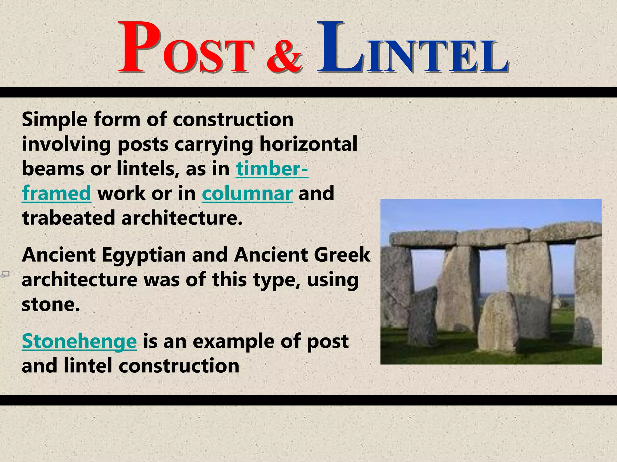


This document provides information on post-lintel structures. It describes post-lintel structures as a simple form of construction using posts carrying horizontal beams or lintels. Ancient Egyptian and Greek architecture commonly used this type of construction with stone. It then discusses the different structural elements of post-lintel structures including columns, column footings, beams, slabs, and stairs. It provides details on sizing and reinforcement of these elements. The document also outlines some advantages of post-lintel structures such as aesthetics, span and space, cost, and sustainability. It describes limitations related to solid to void ratios and placement of openings and stairs.
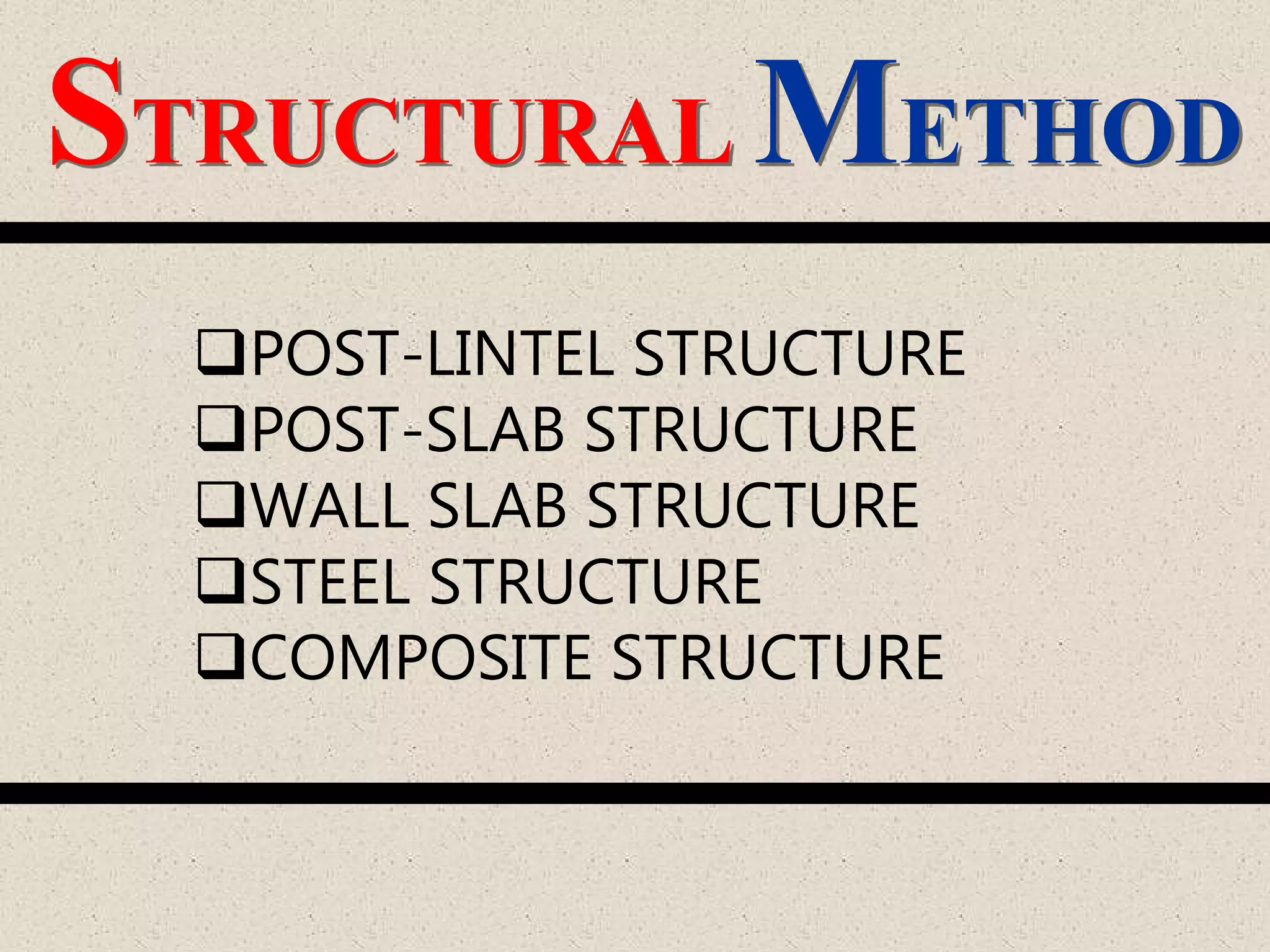
Introduction to post-lintel as a structural method, encompassing types such as wall slab, steel, and composite structures.
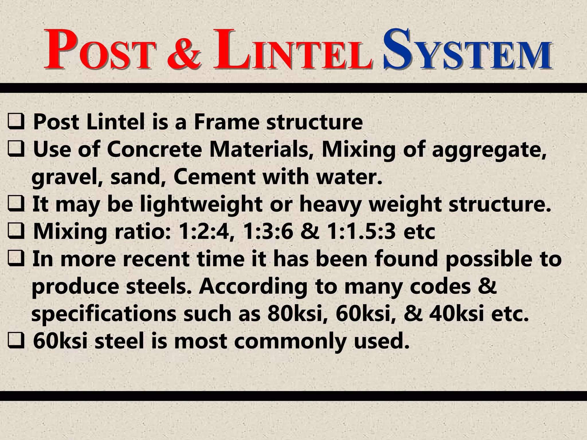
Description of post & lintel as a construction method, example of Stonehenge, concrete mixing ratios, and standard steel specifications.
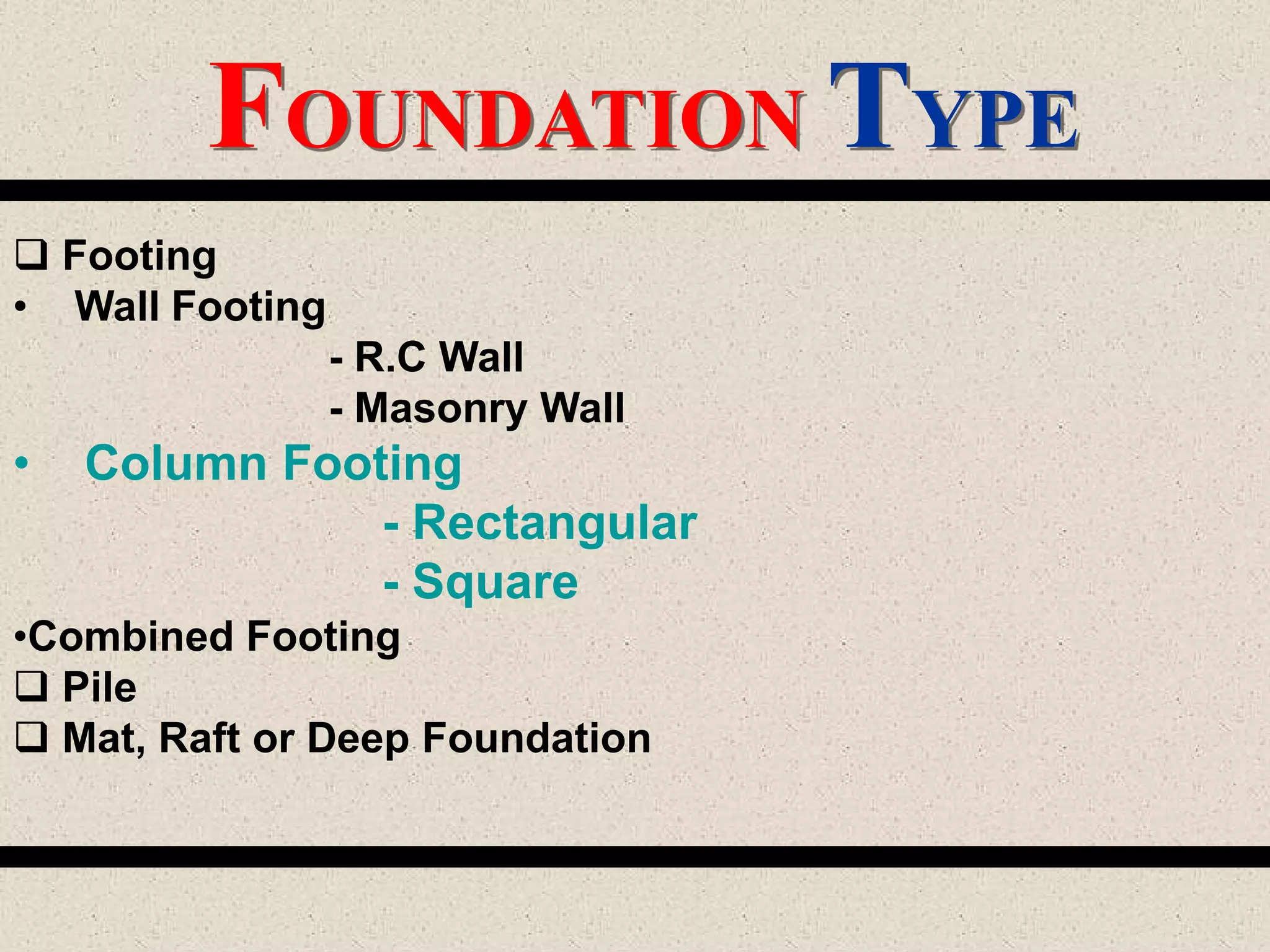
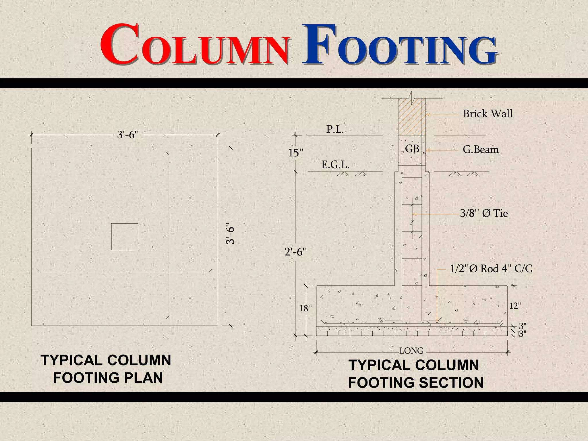
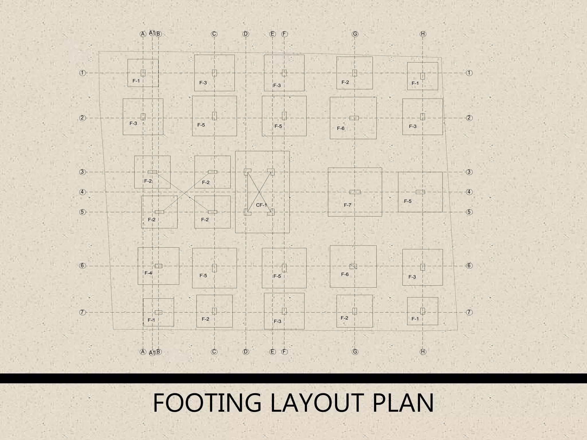
Discussion of foundation types including wall footing, column footing, and typical designs for column footings.
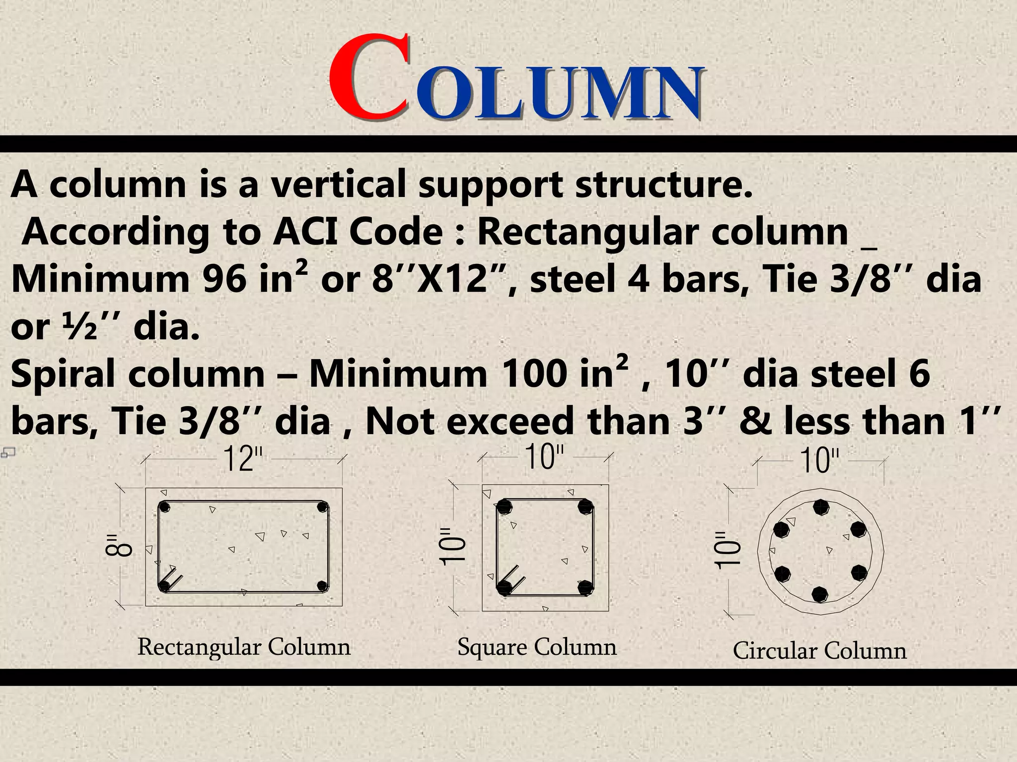
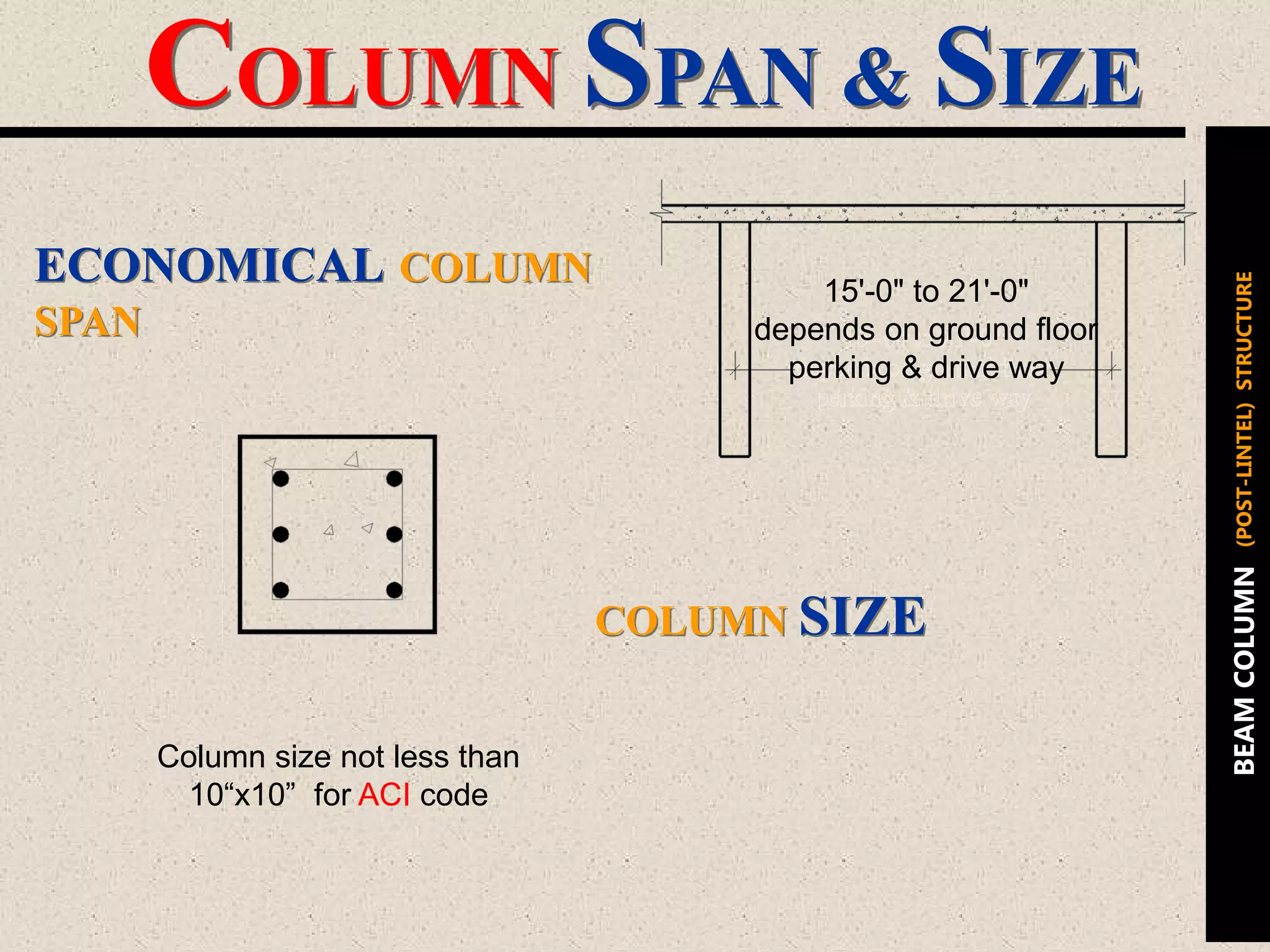
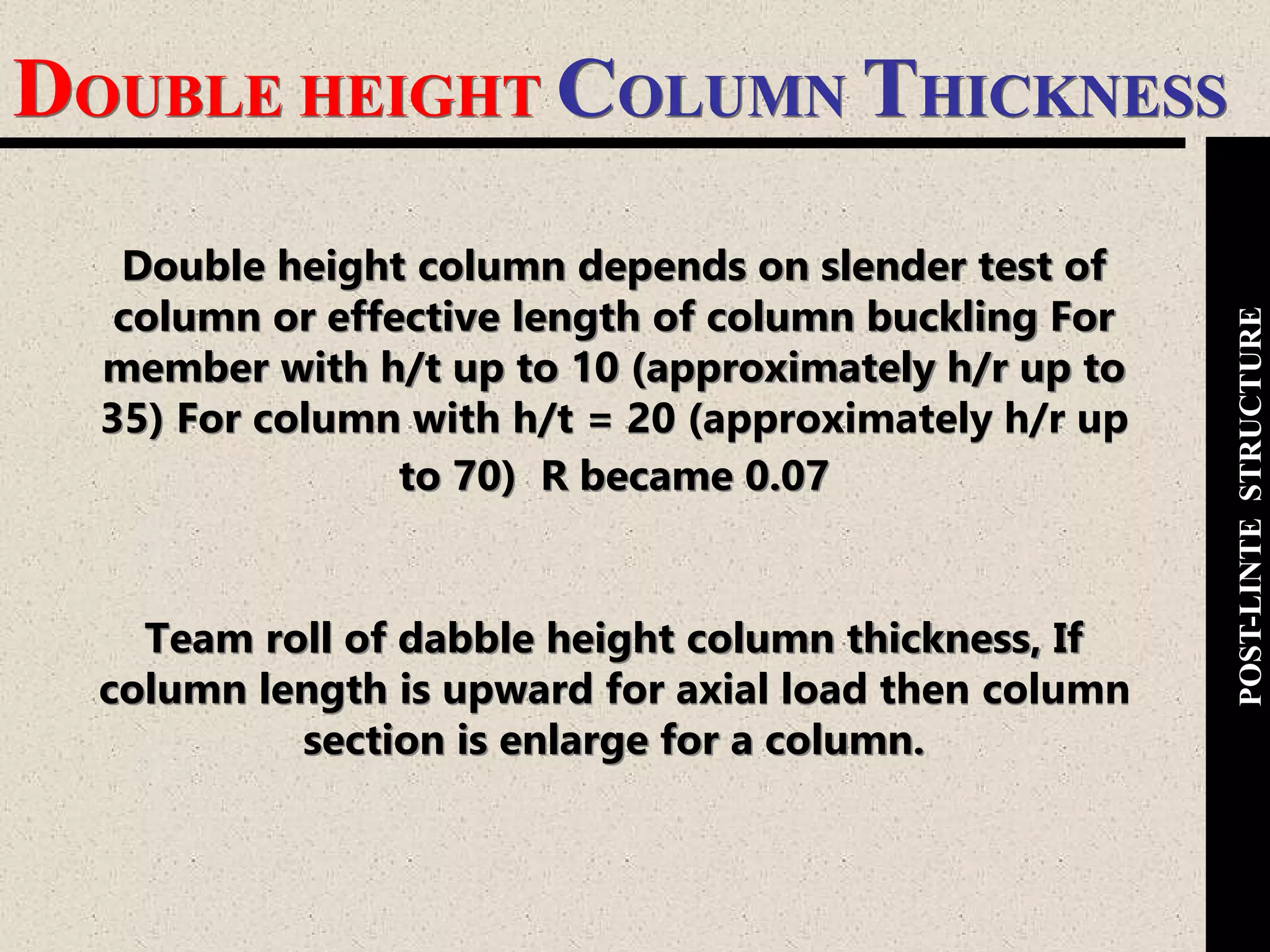
Details various column types and their specifications as per ACI codes, including dimensions and reinforcement standards.
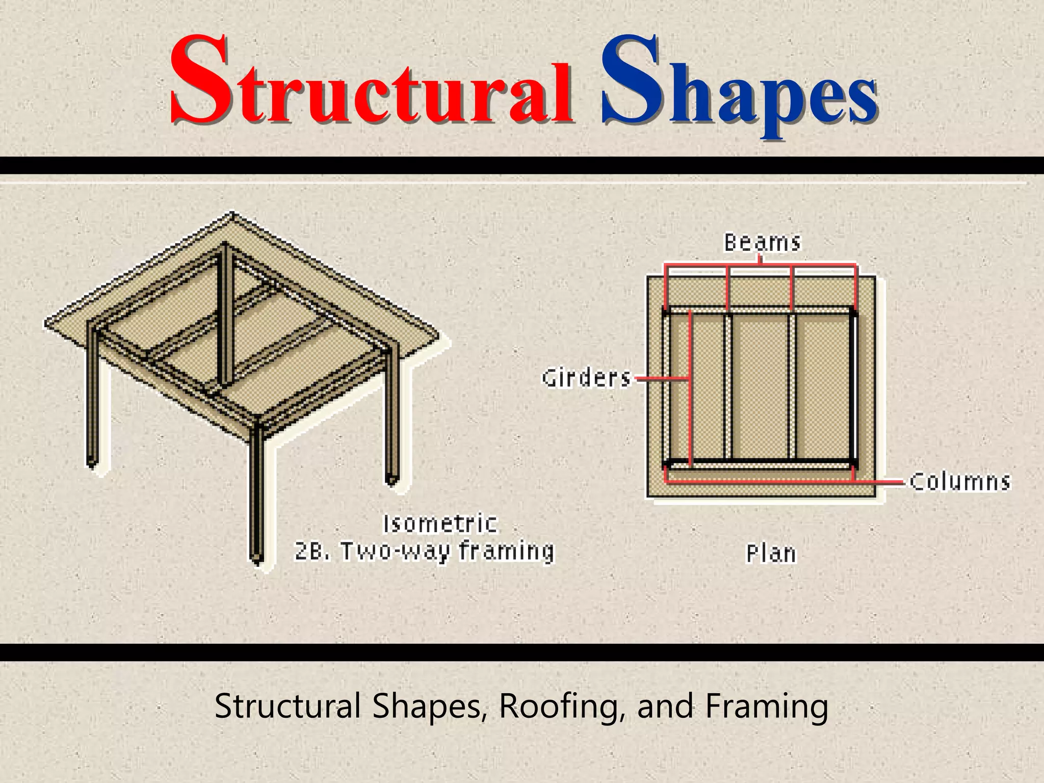
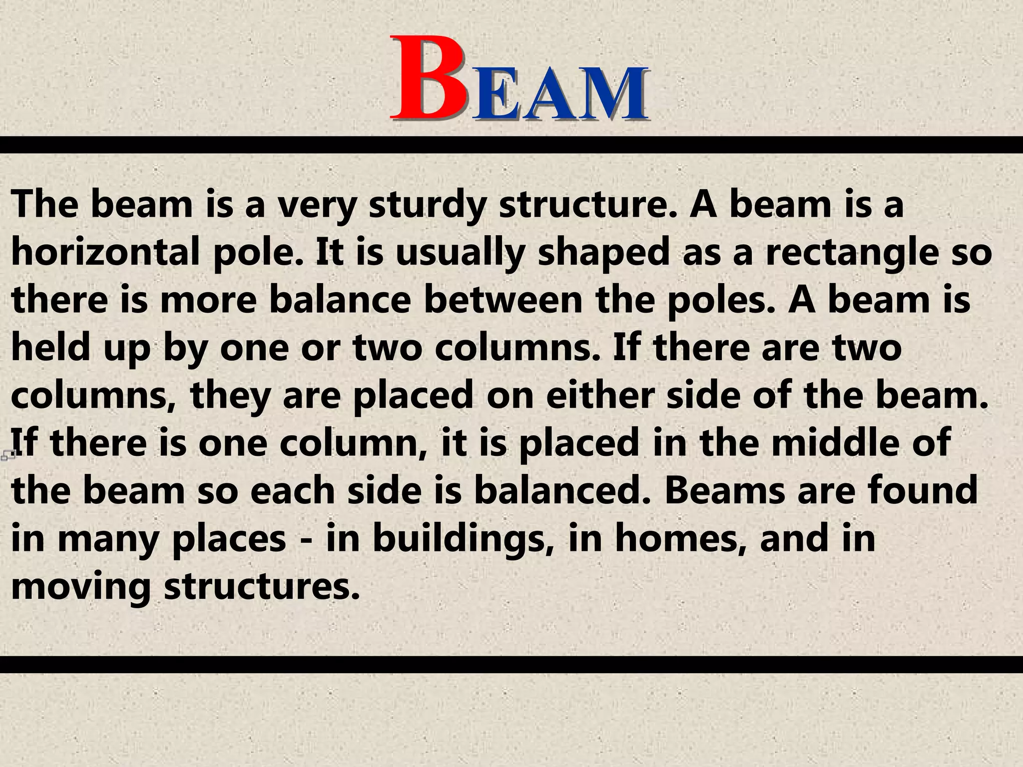
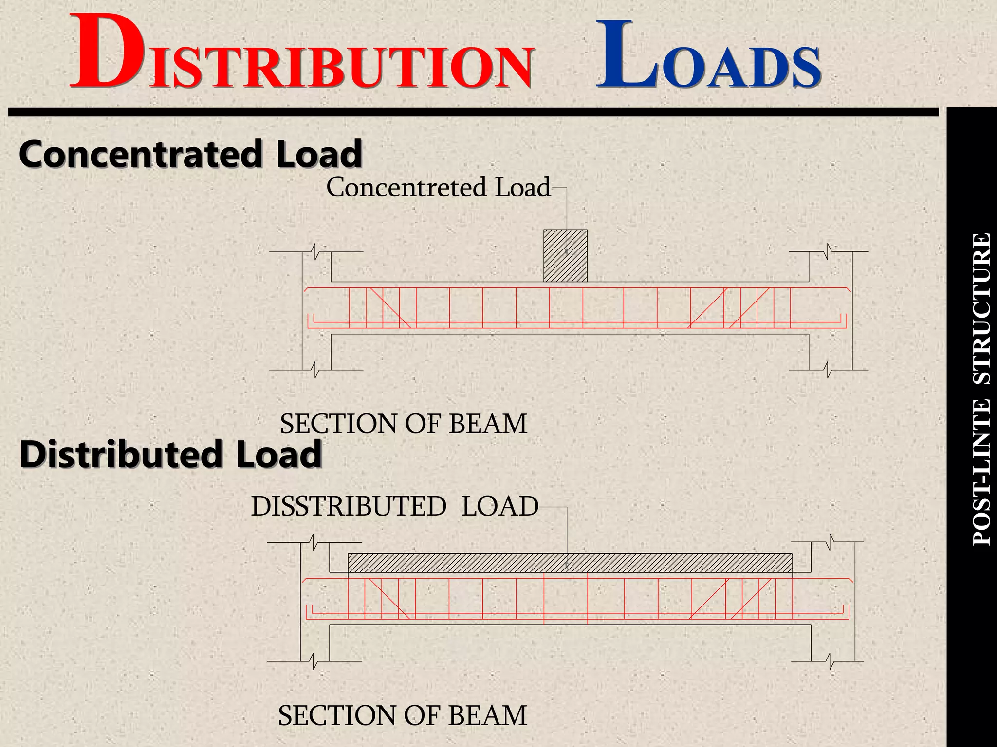
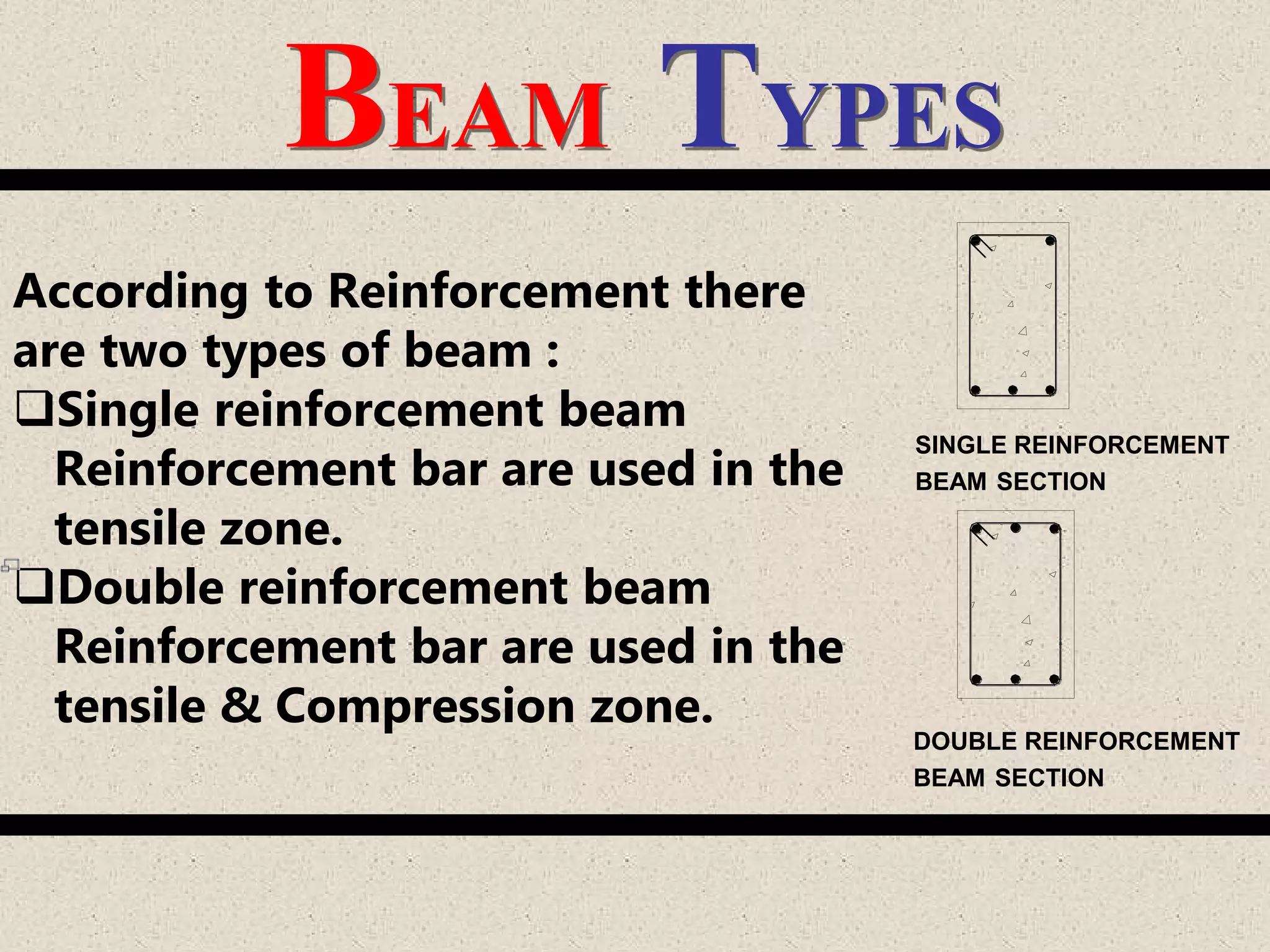
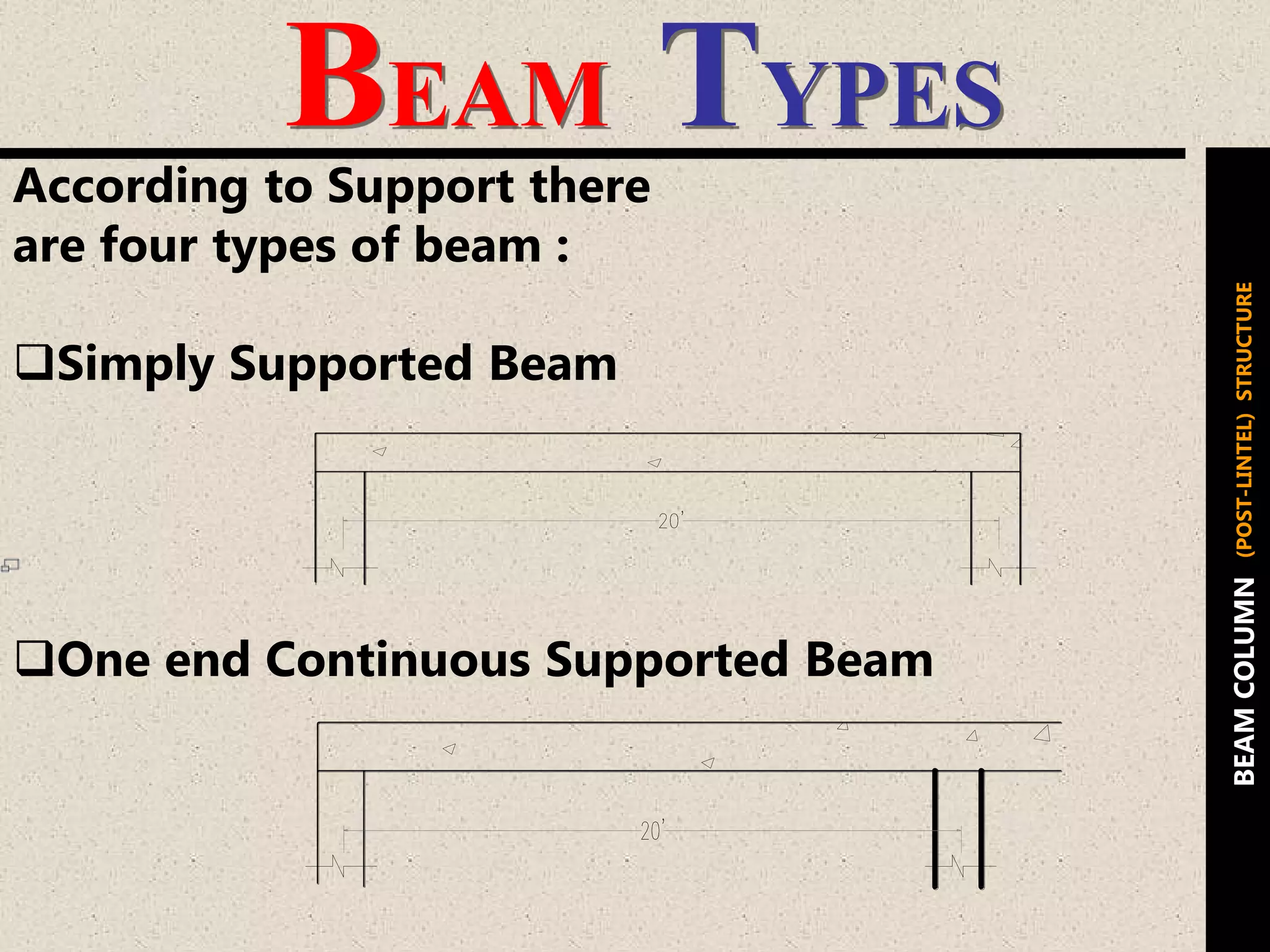
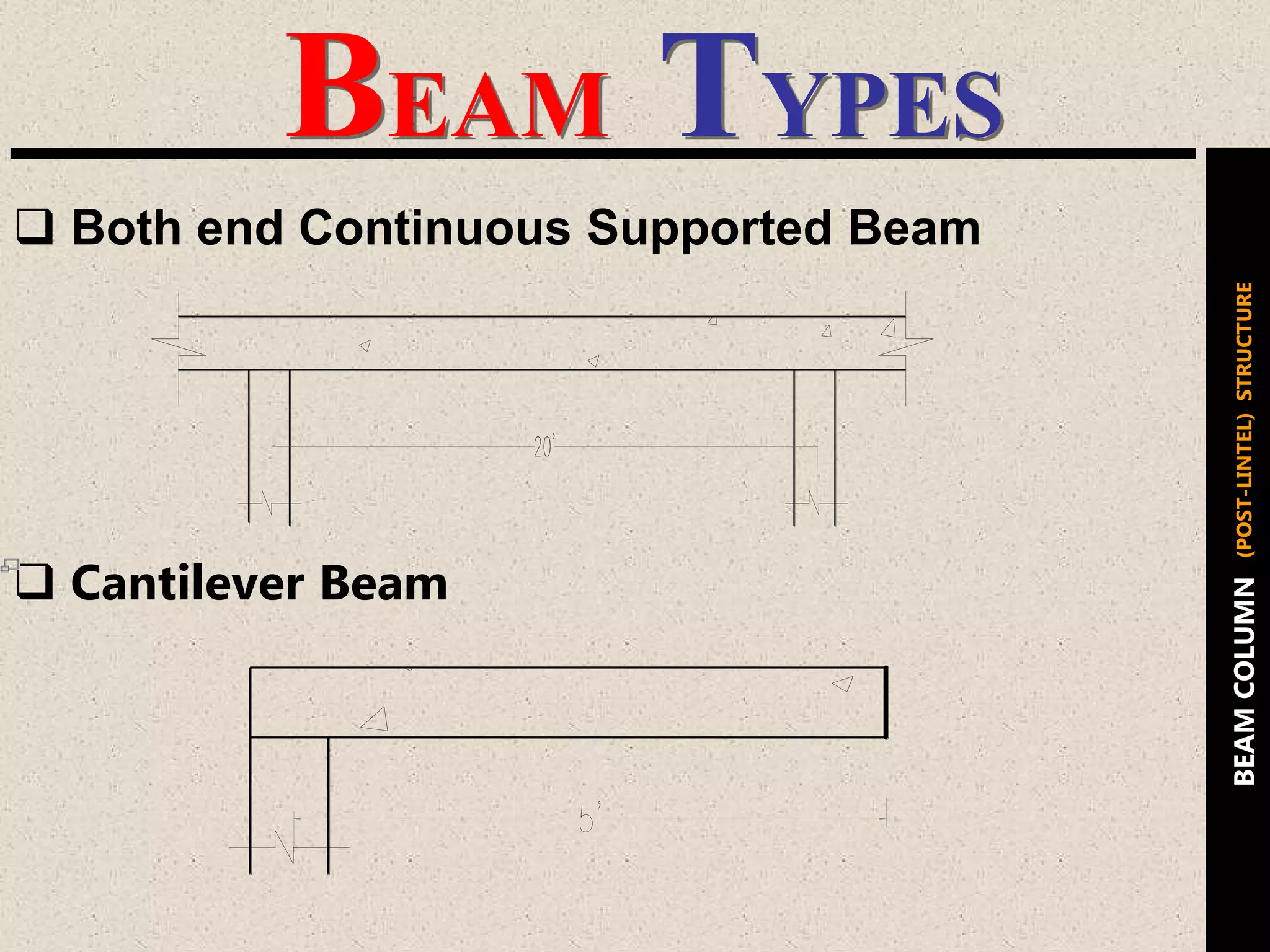
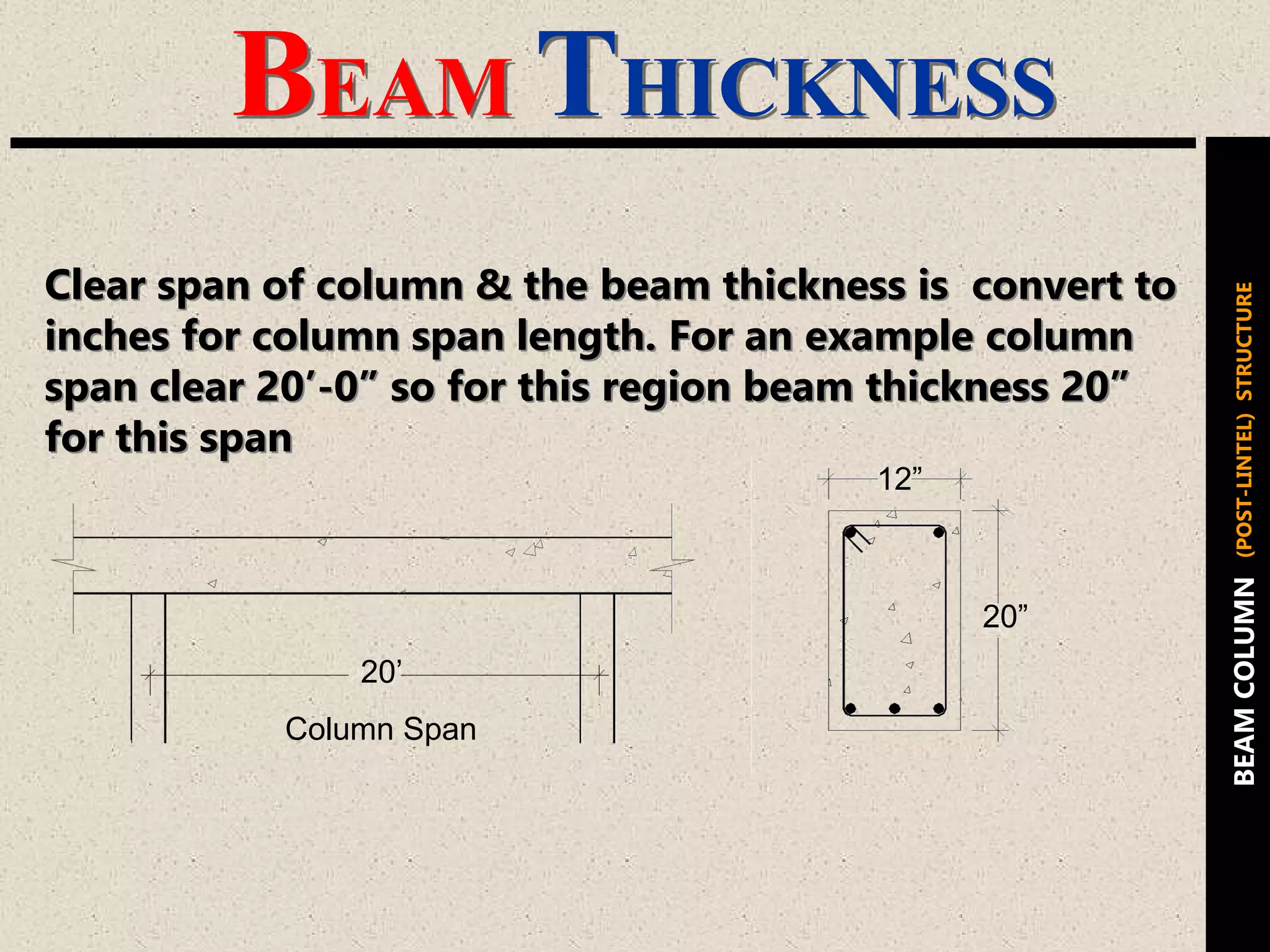
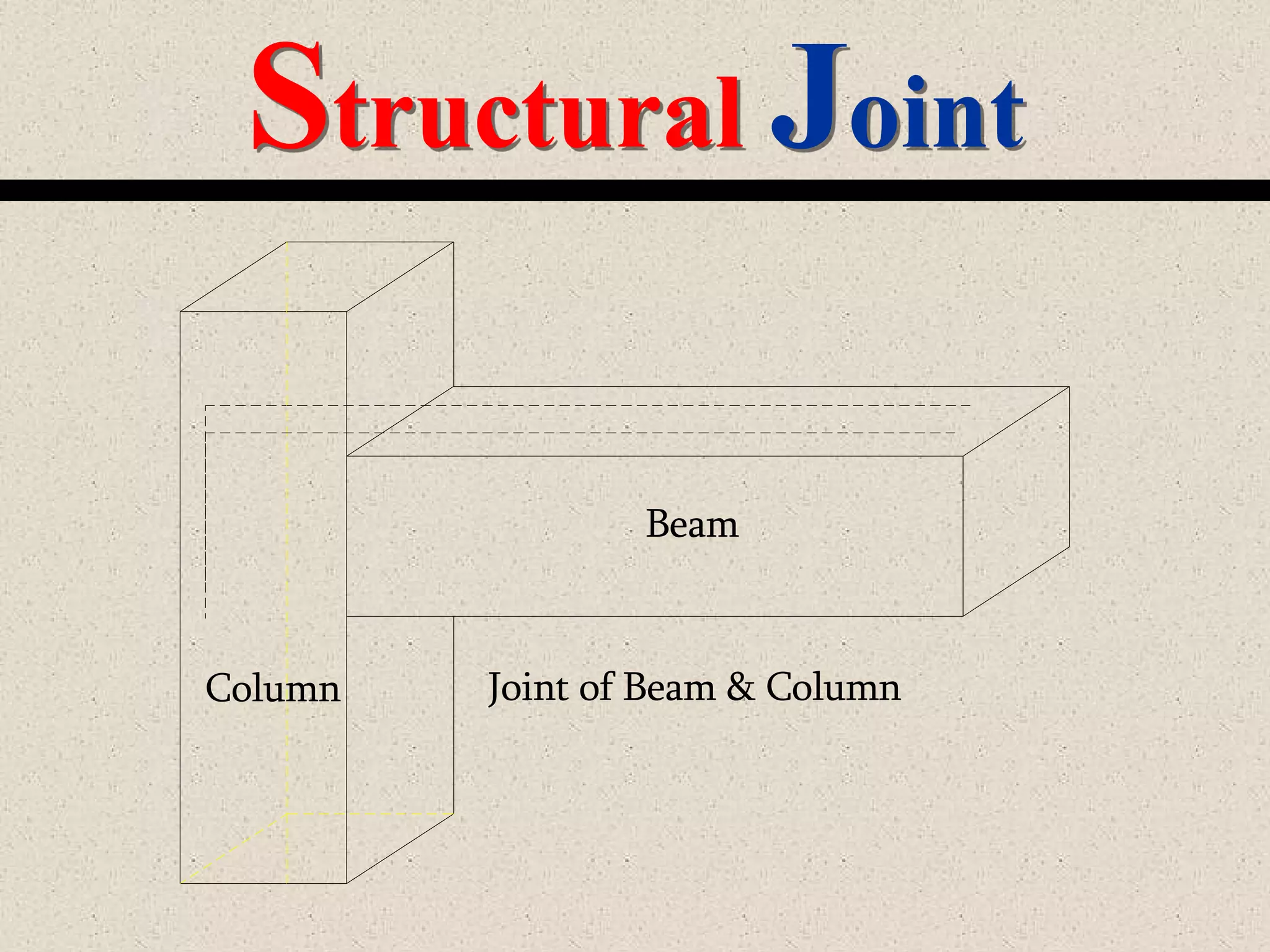
Description of beam functionality, types of loads, types of beams based on support, and structural joints.
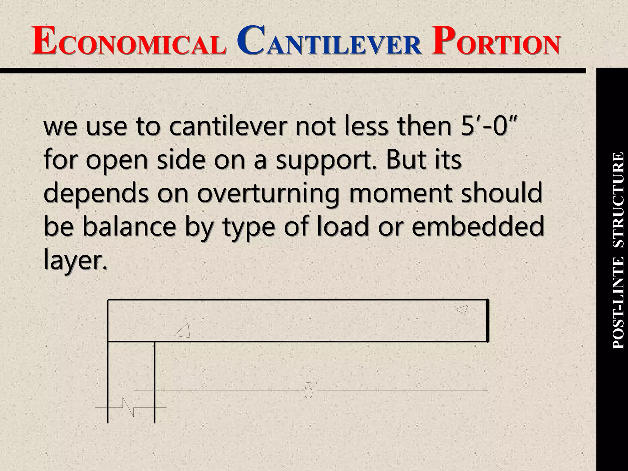
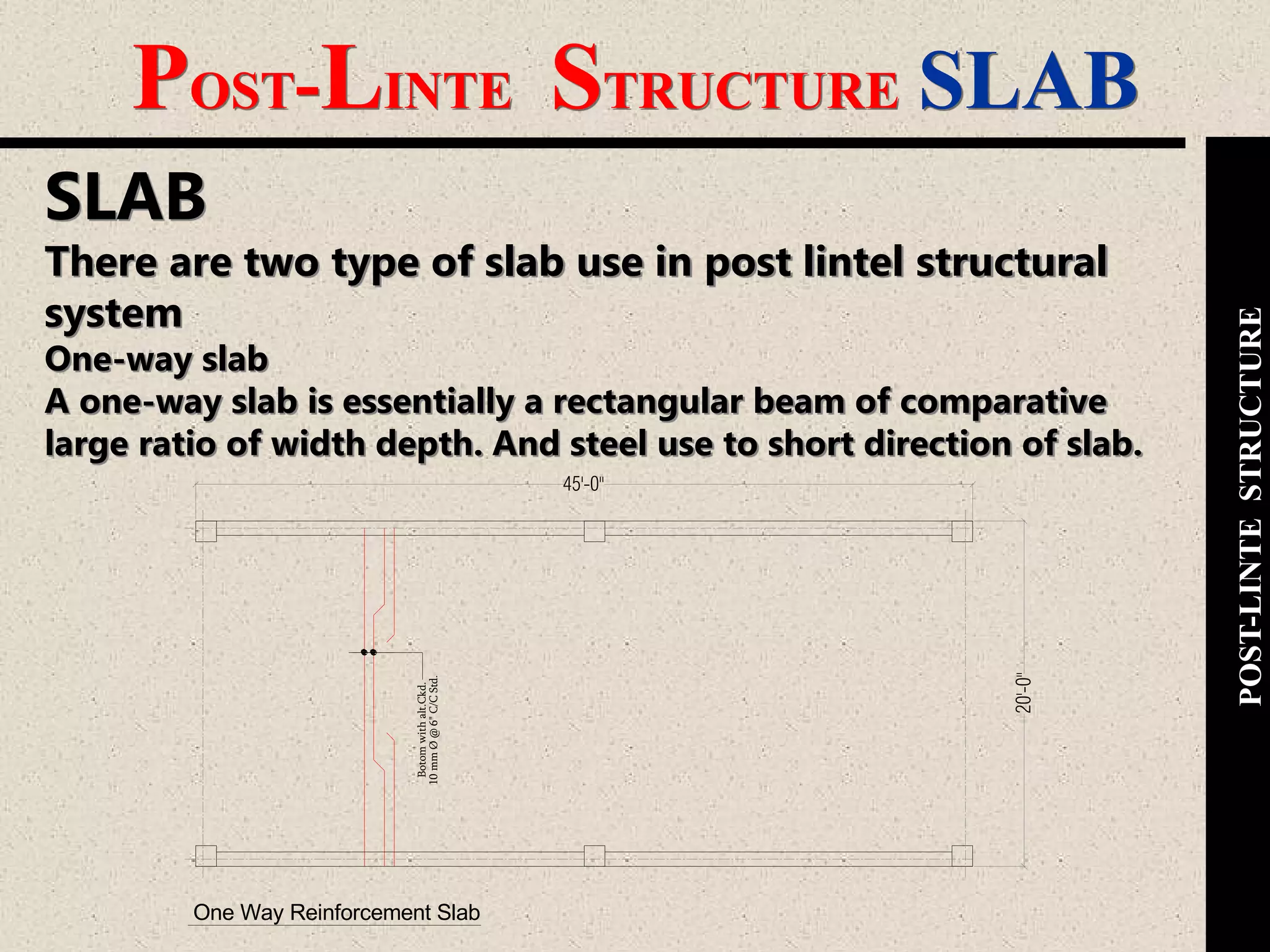
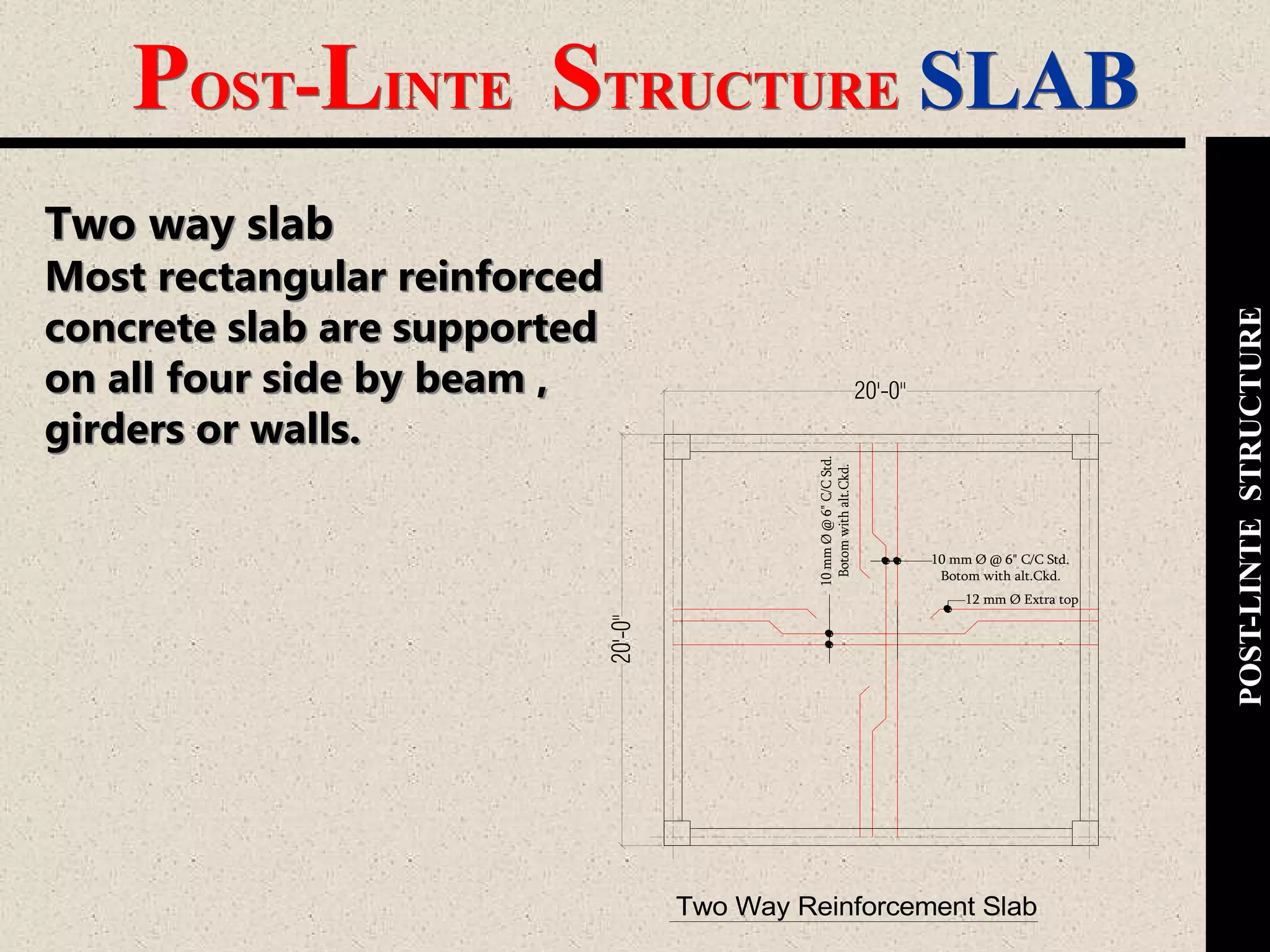
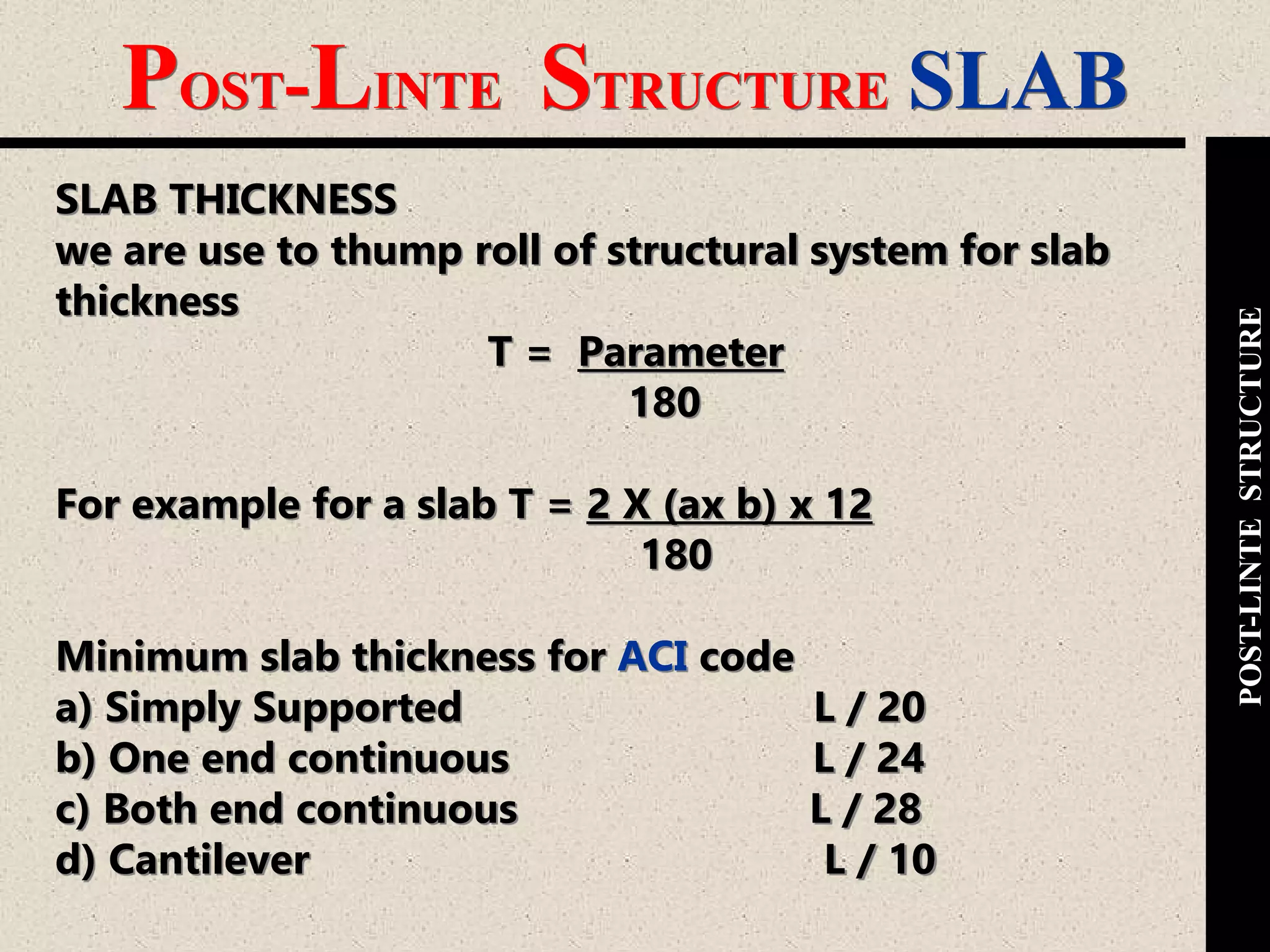
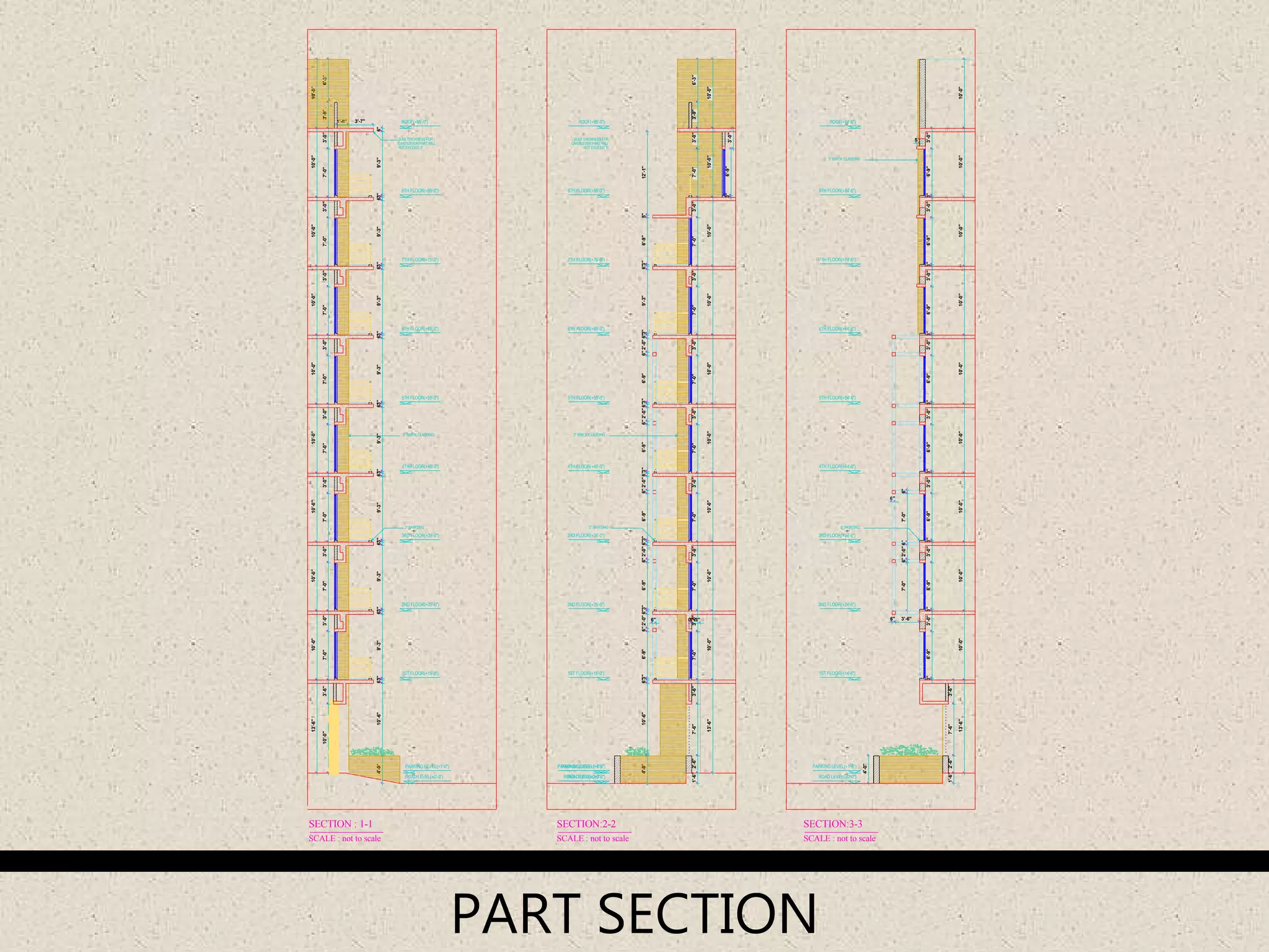
Explains cantilever requirements and slab types, including one-way and two-way slabs with reinforcement specifications.
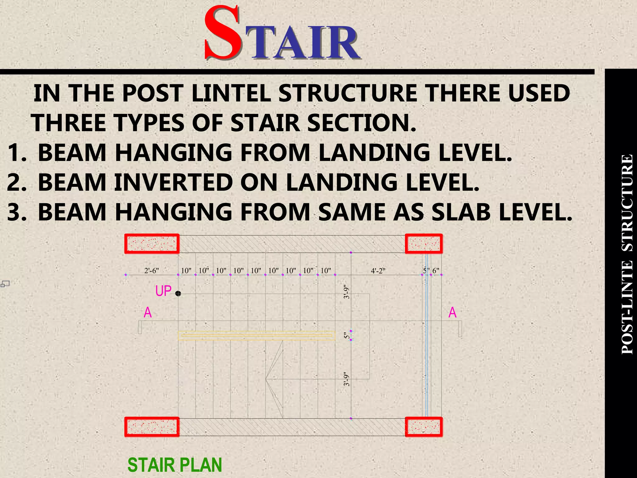
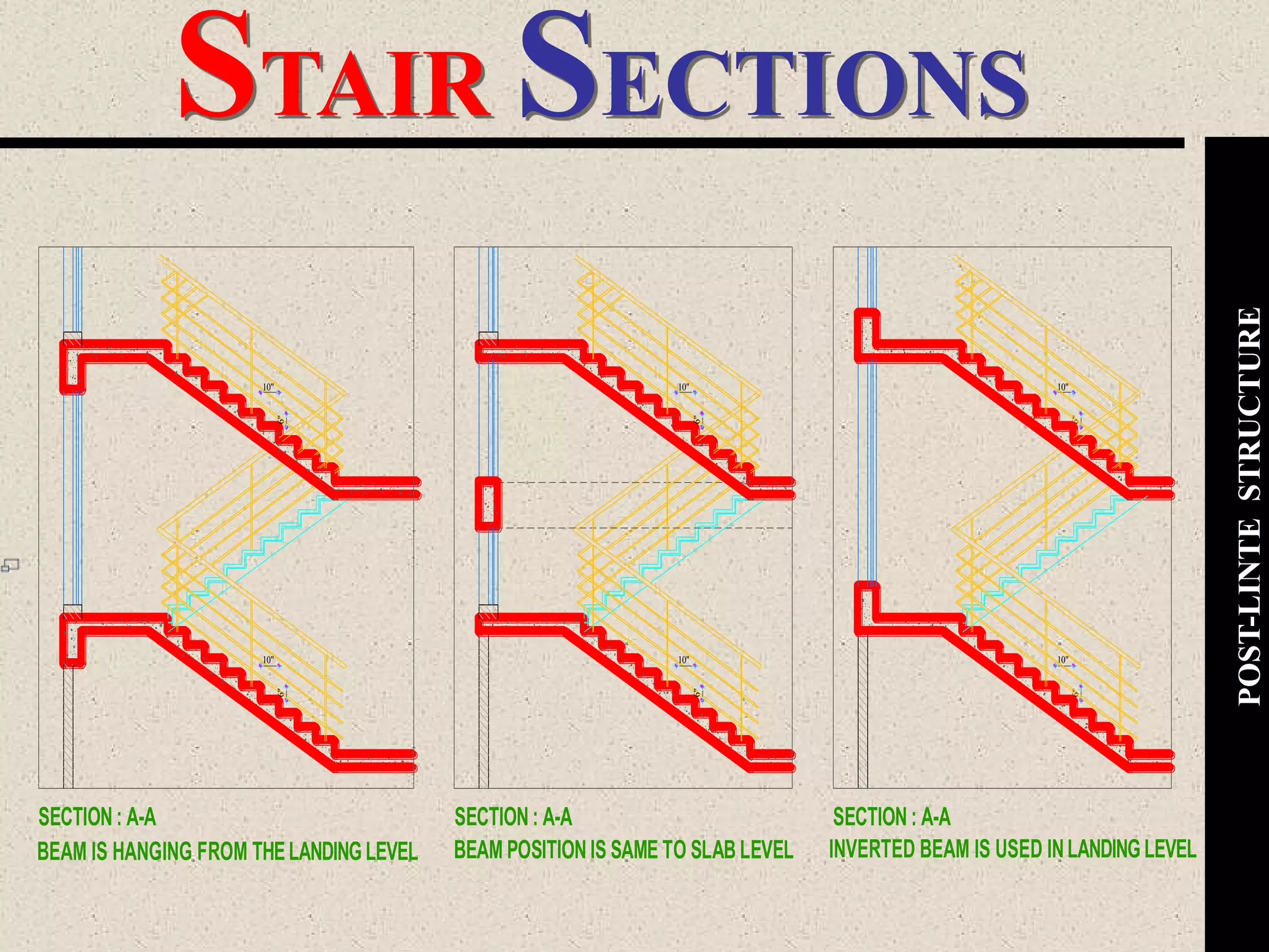
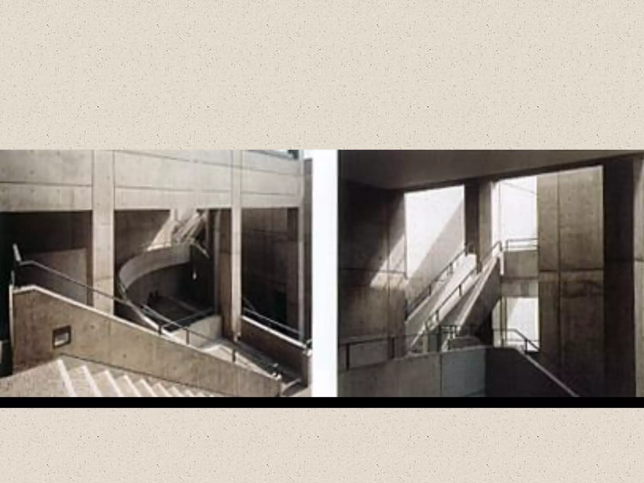
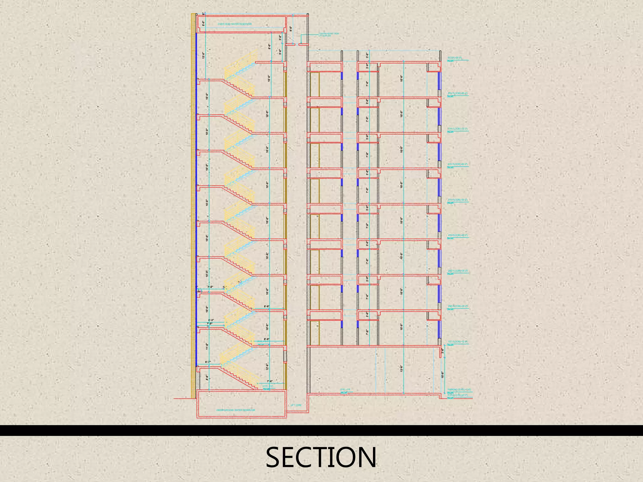
Three types of stair section designs within post-lintel structures and their arrangements.
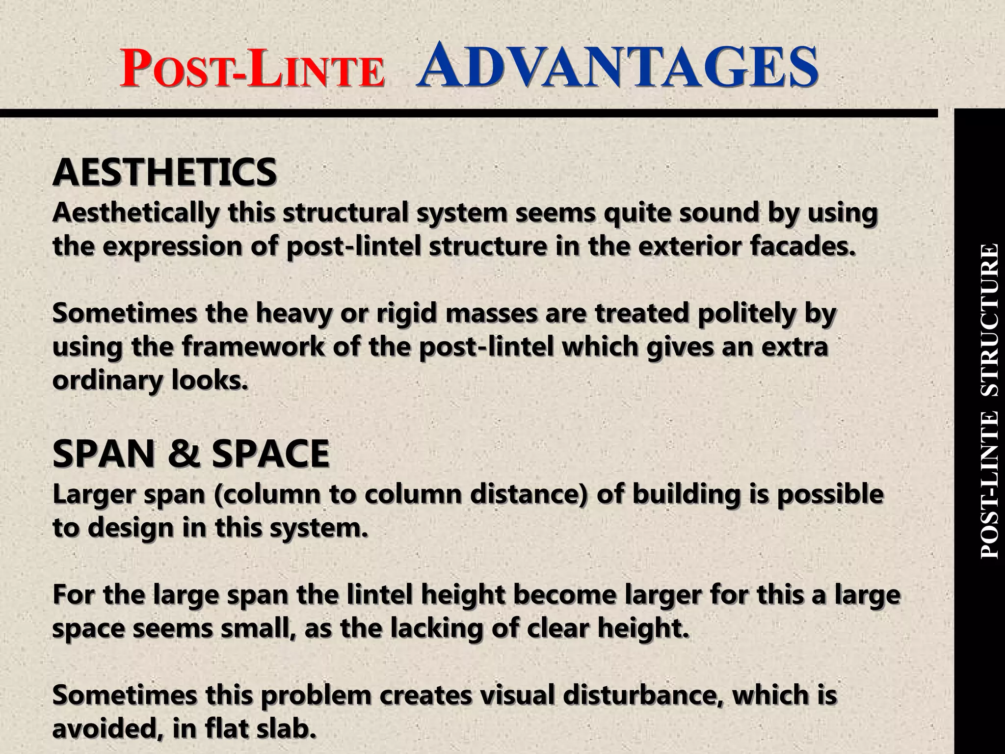
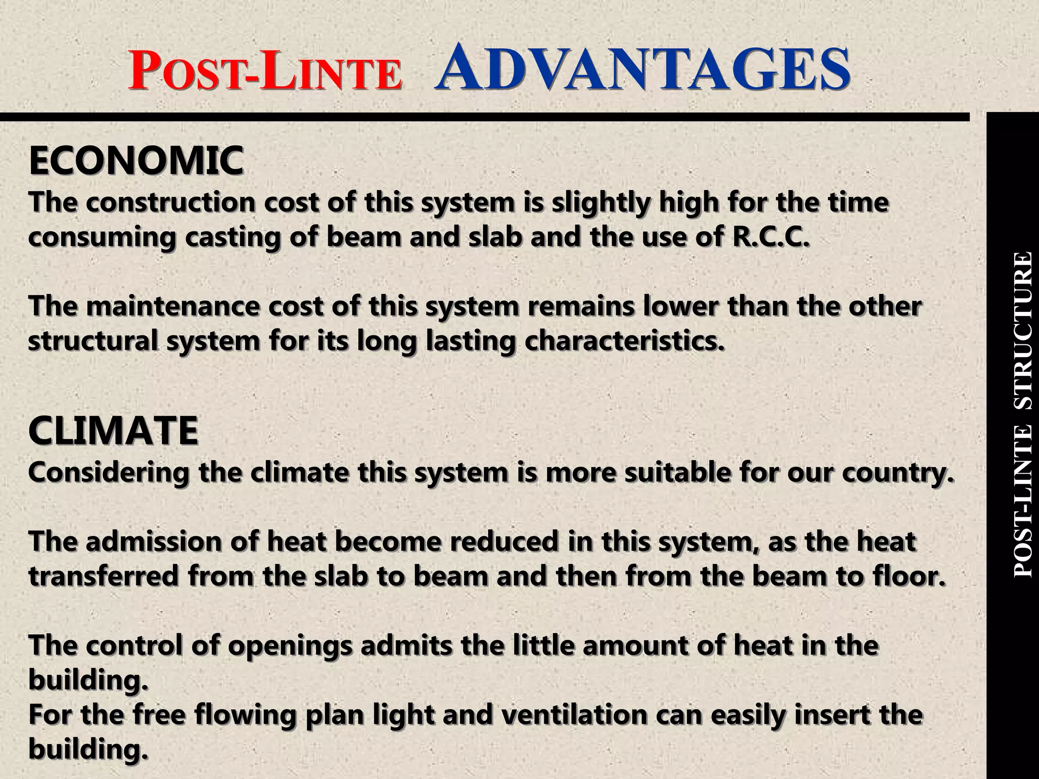
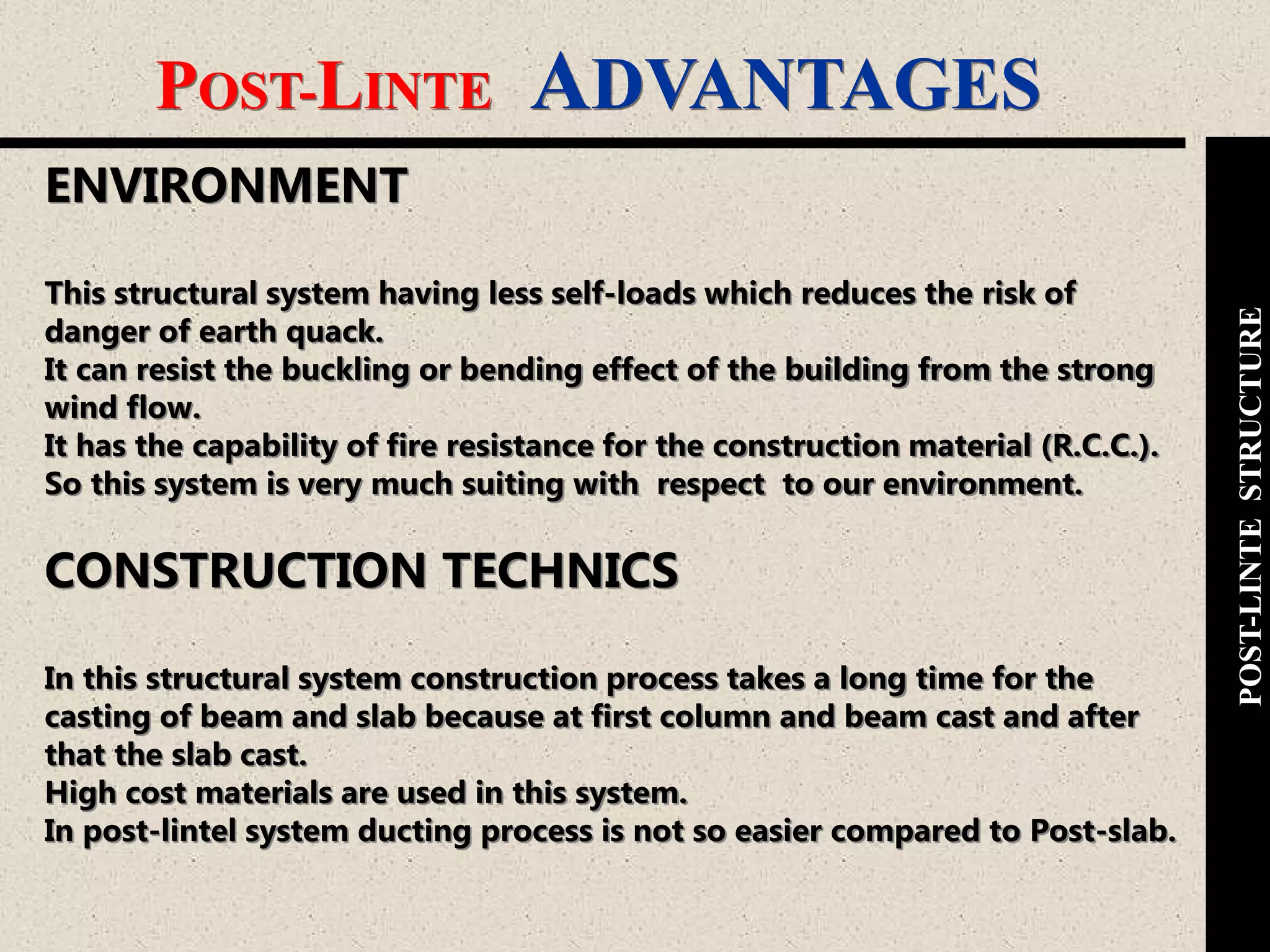
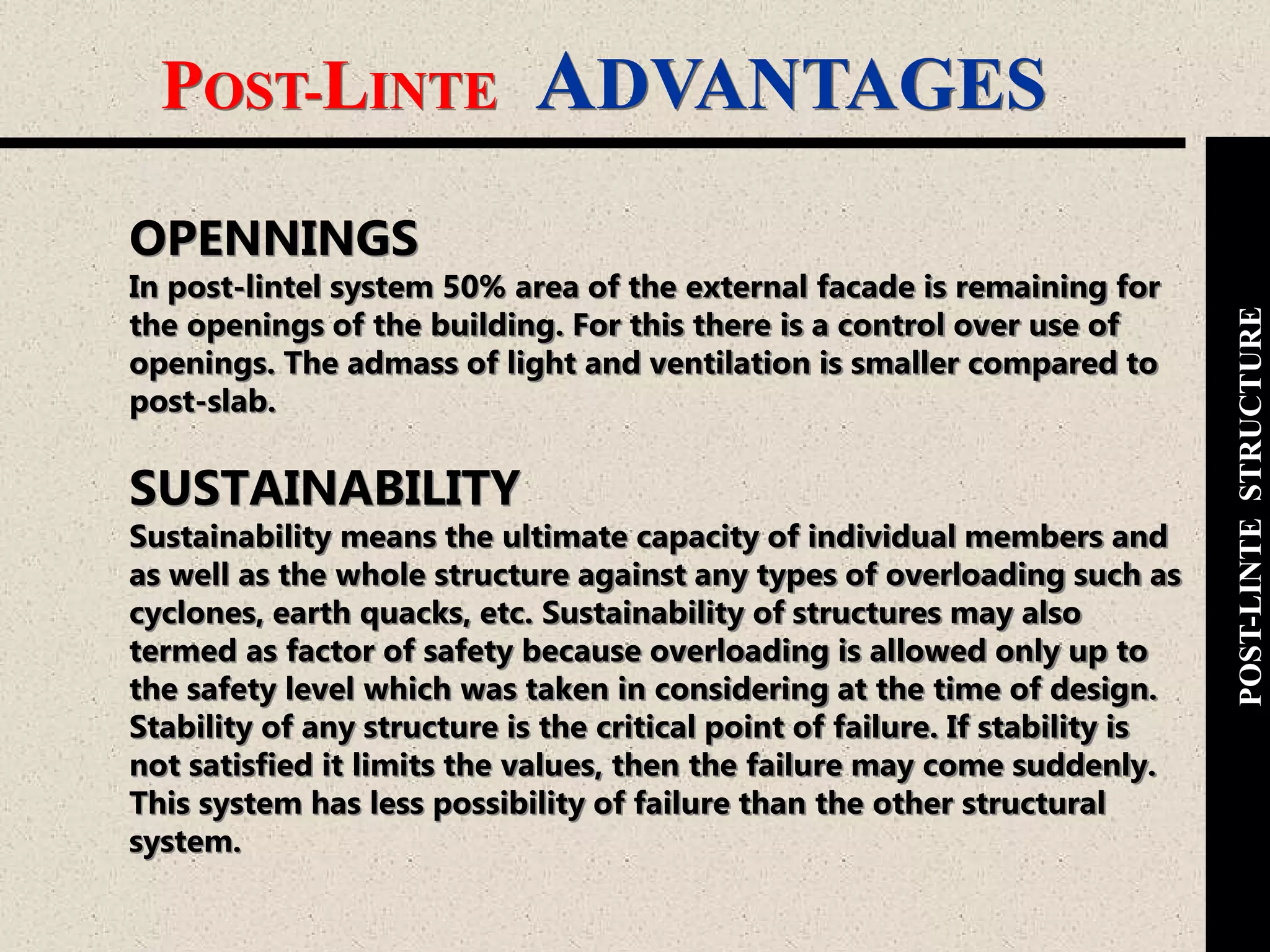
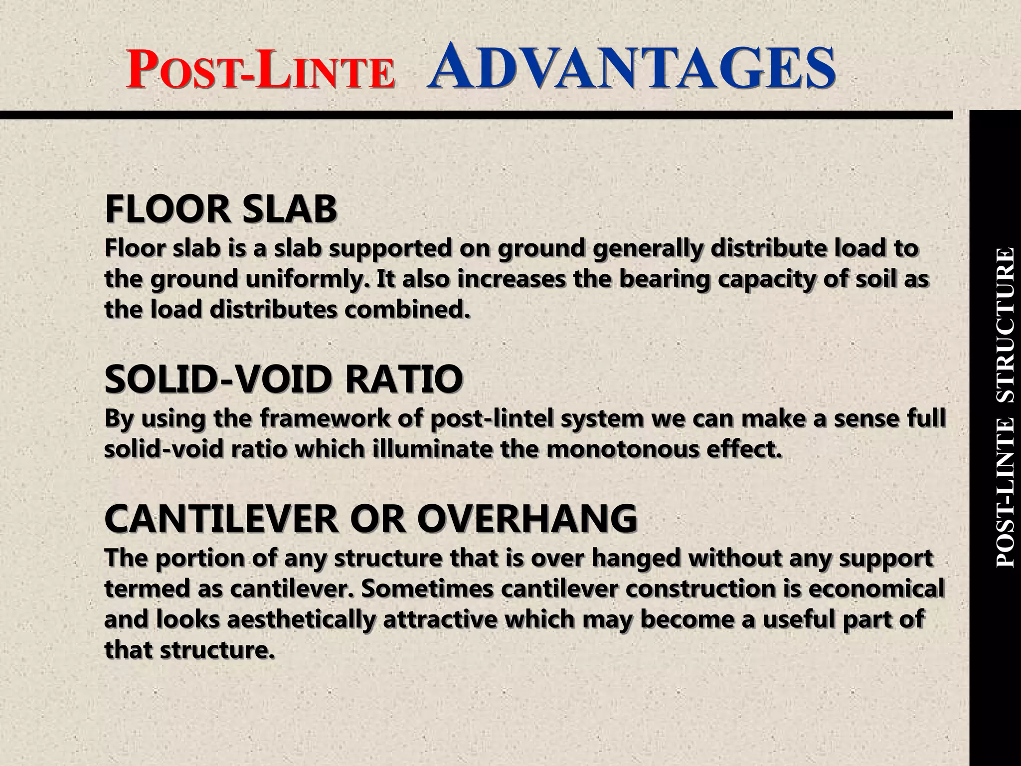
Highlights aesthetic appeal, economic benefits, environmental impact, sustainability, and structural advantages of the post-lintel system.
Highlights aesthetic appeal, economic benefits, environmental impact, sustainability, and structural advantages of the post-lintel system.
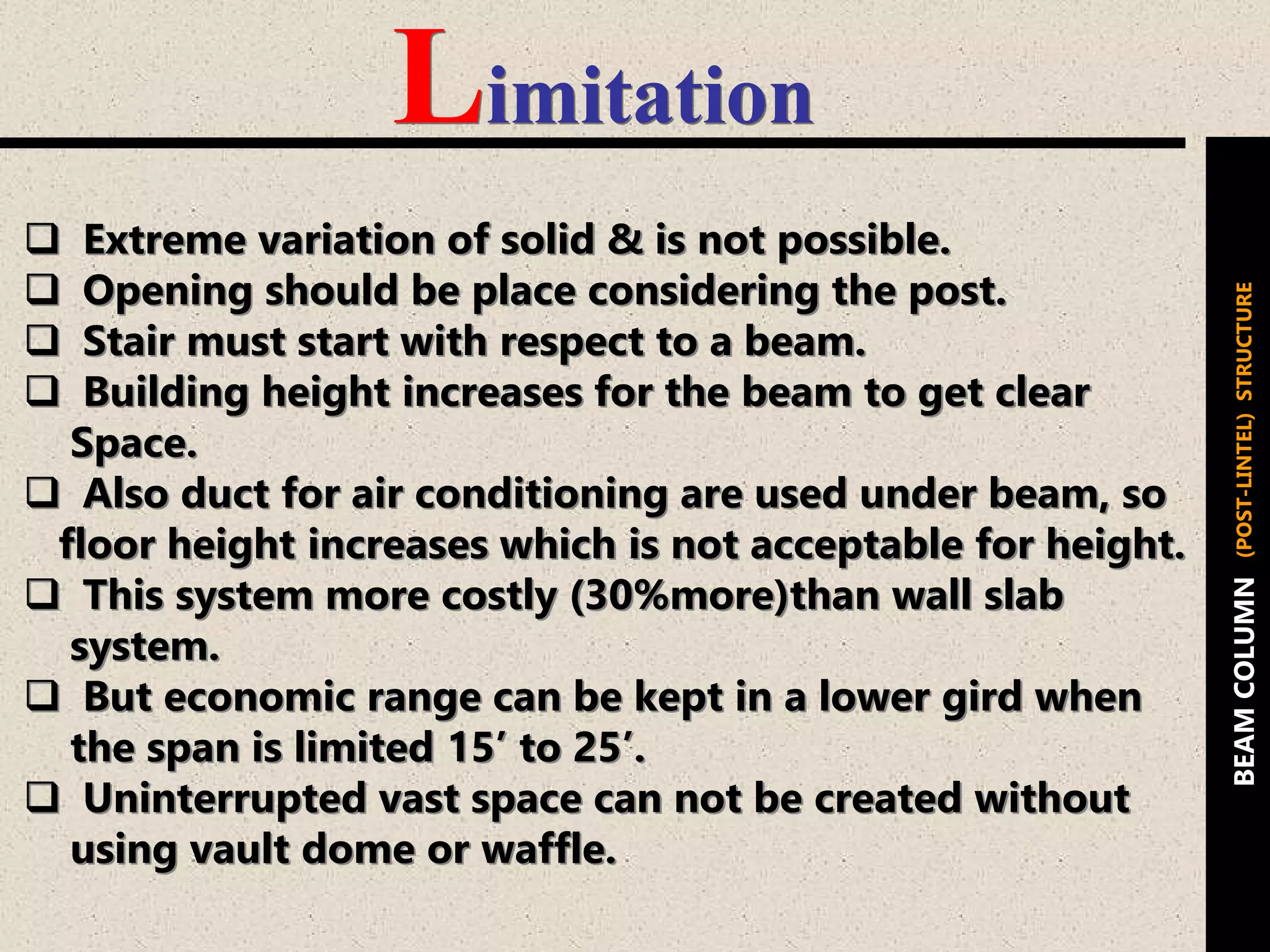
Discusses the limitations of post-lintel structures concerning height, openings, and cost compared to other systems.
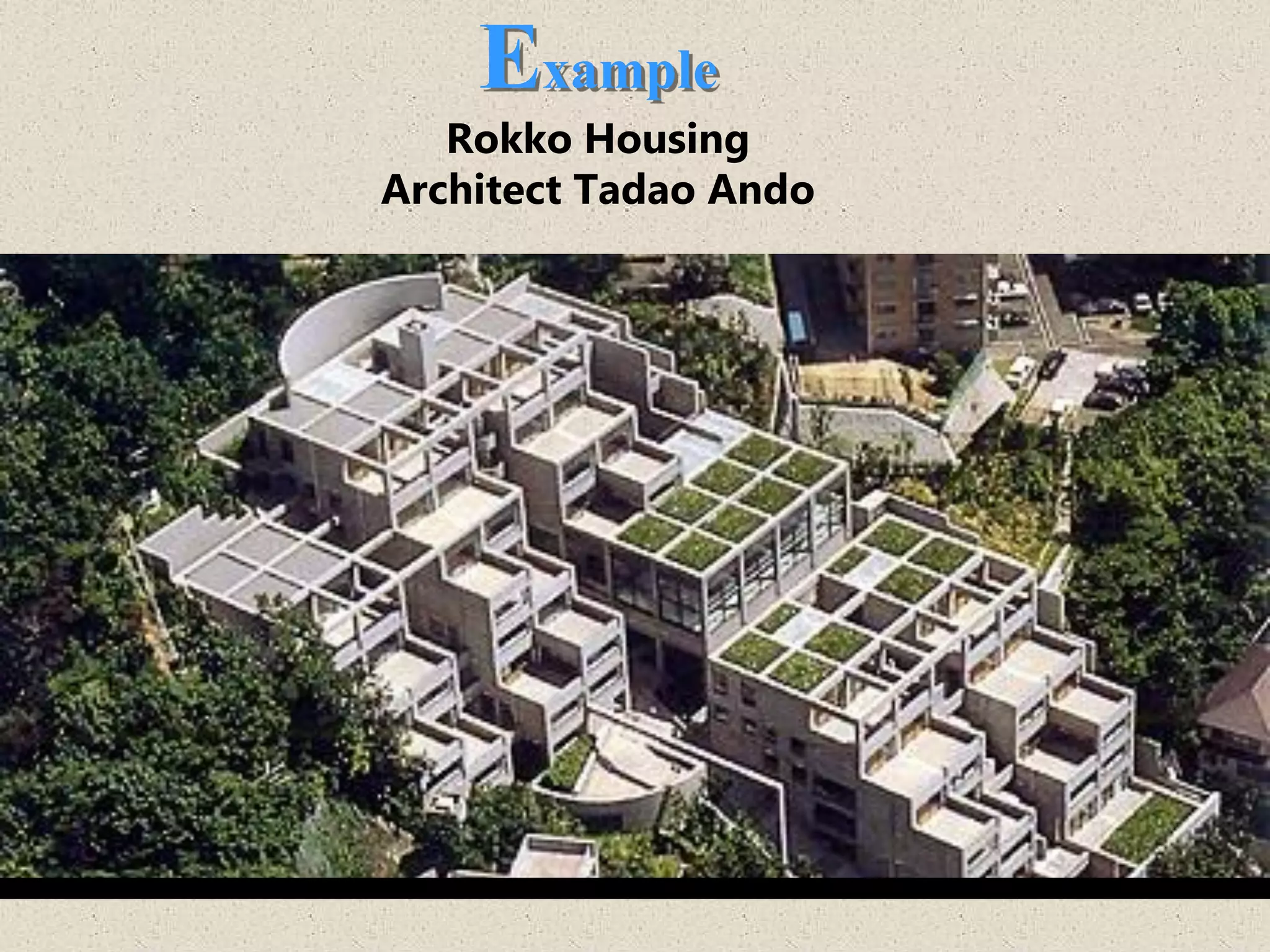
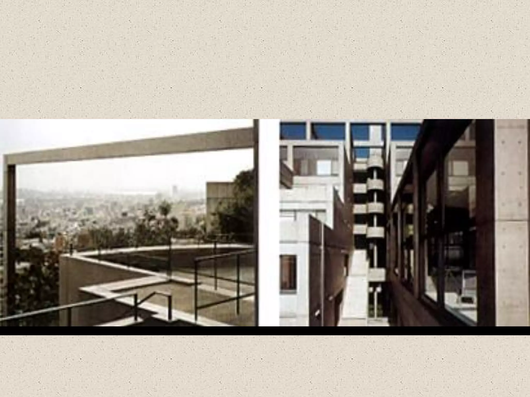
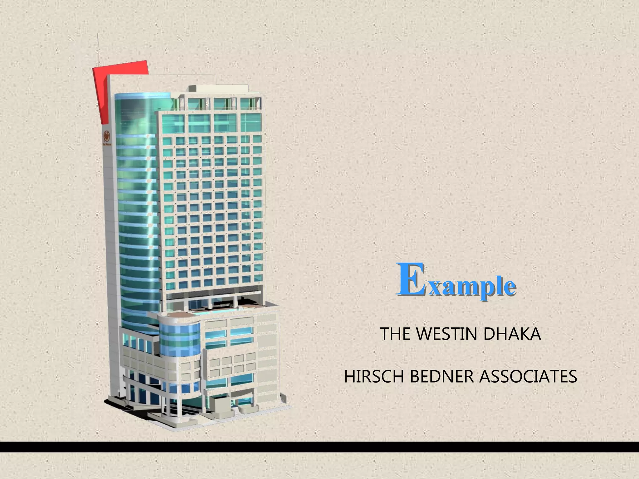
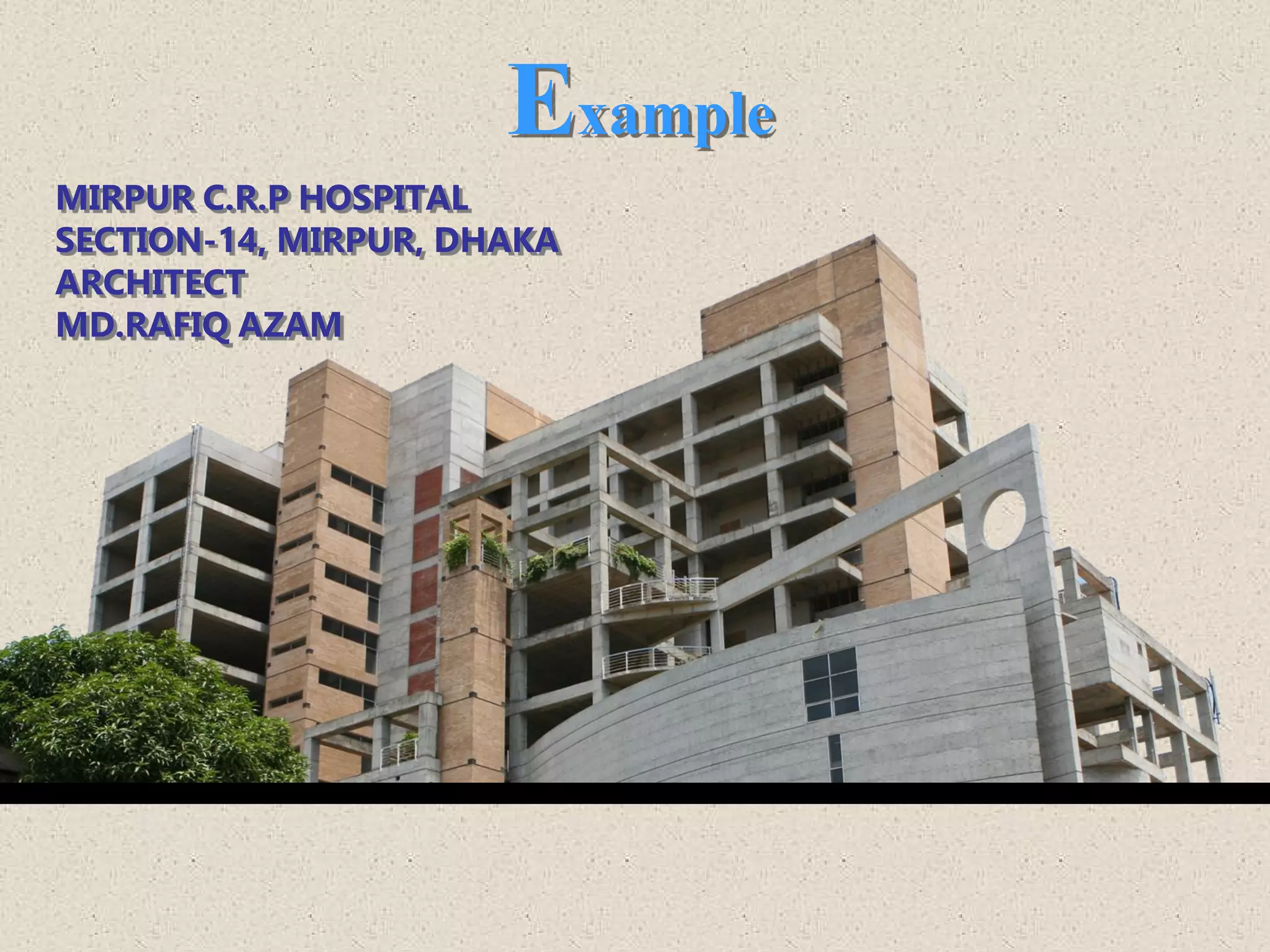
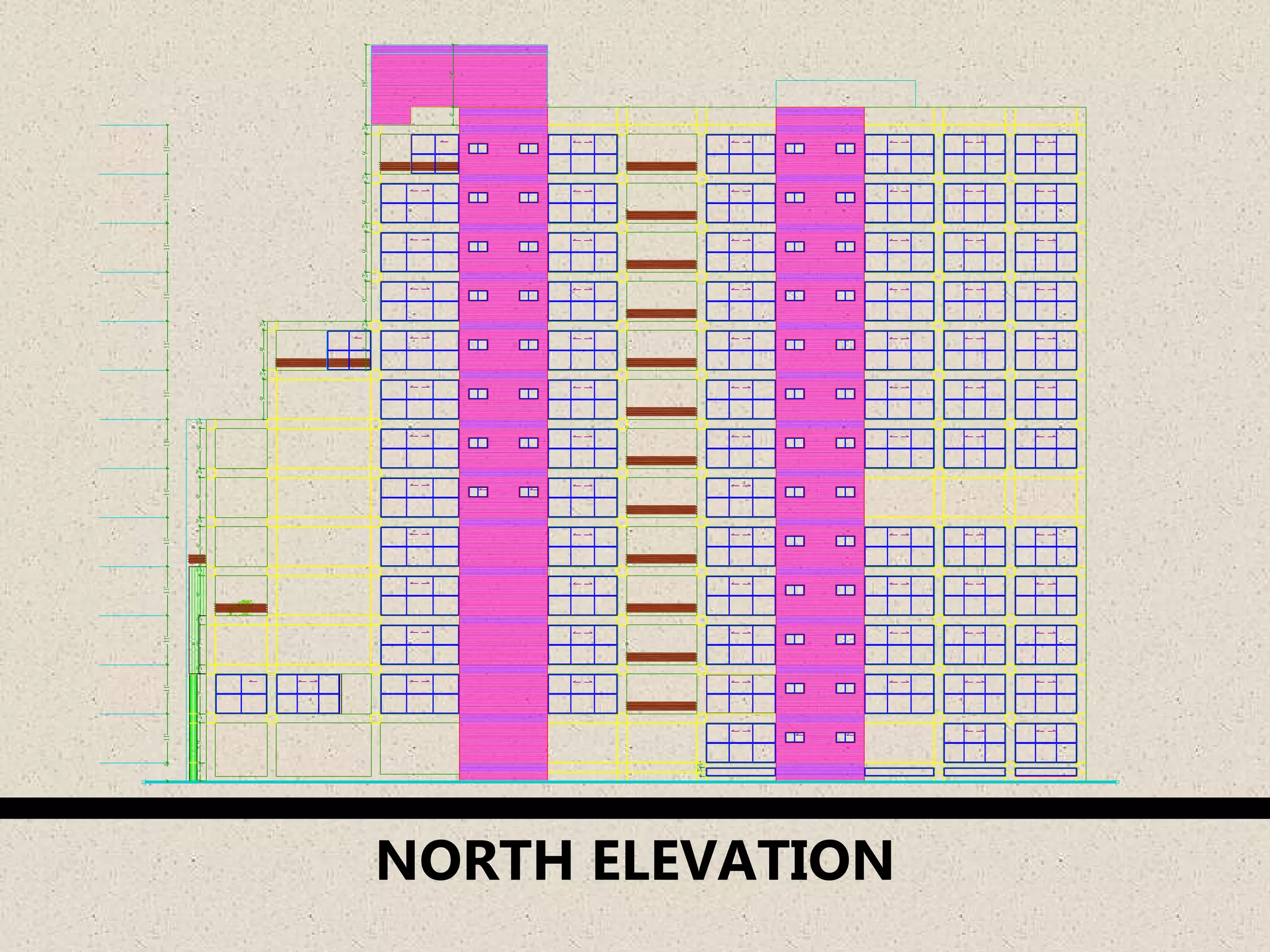
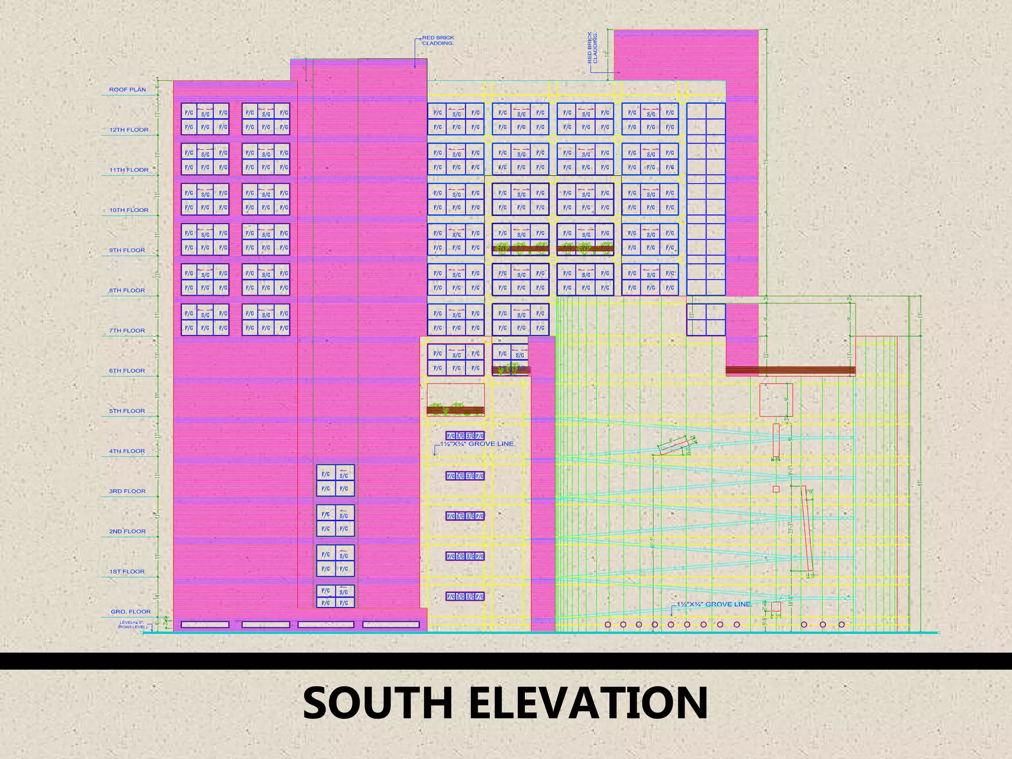
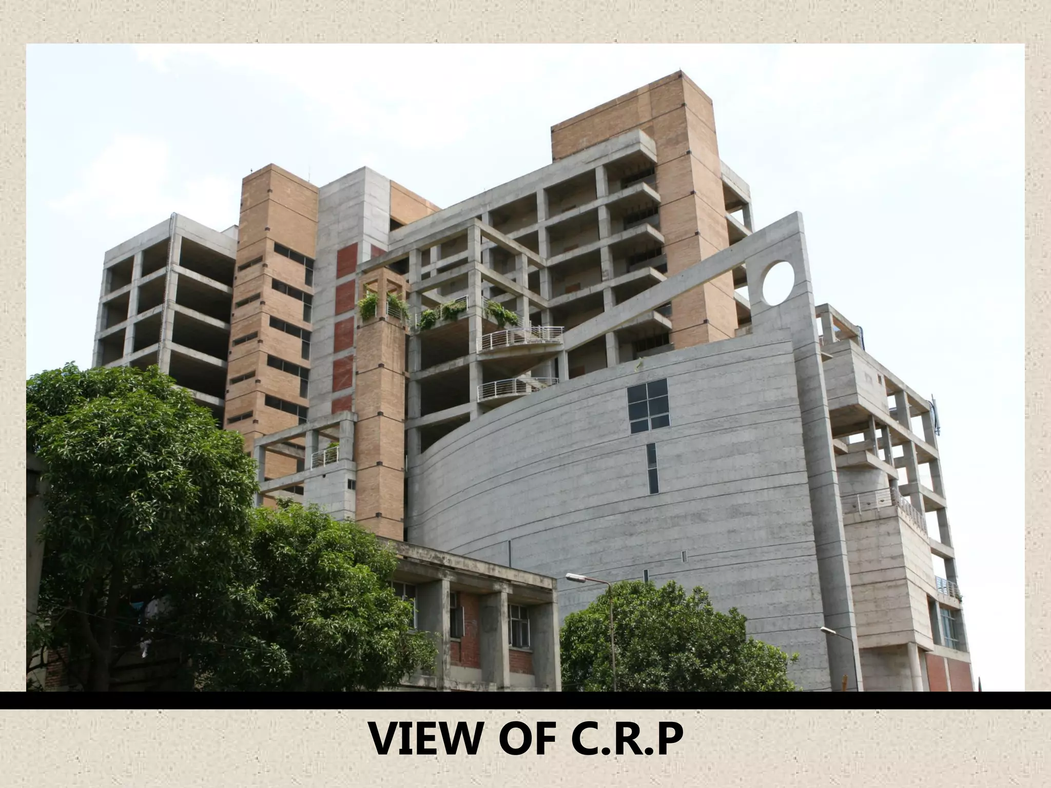
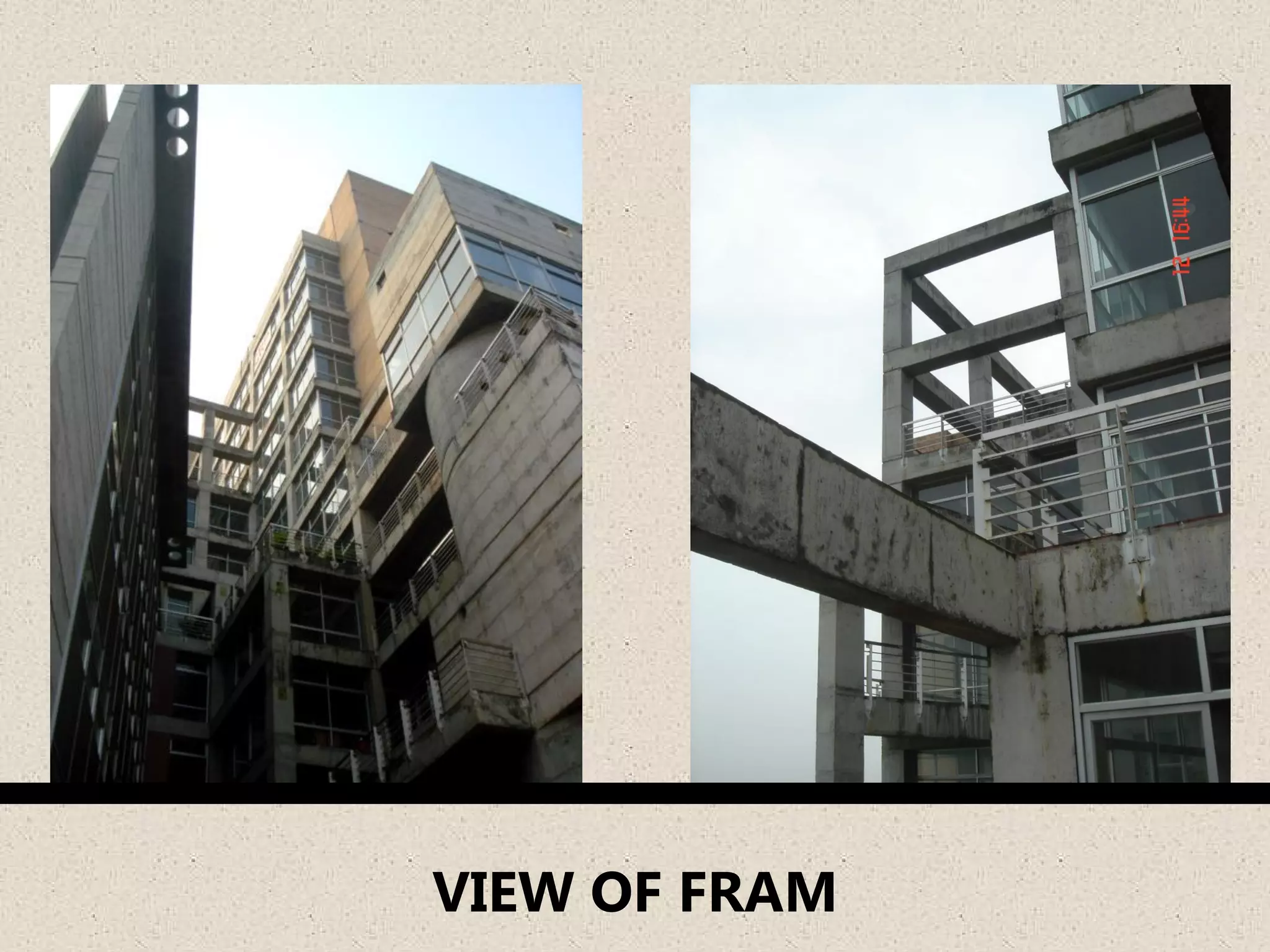
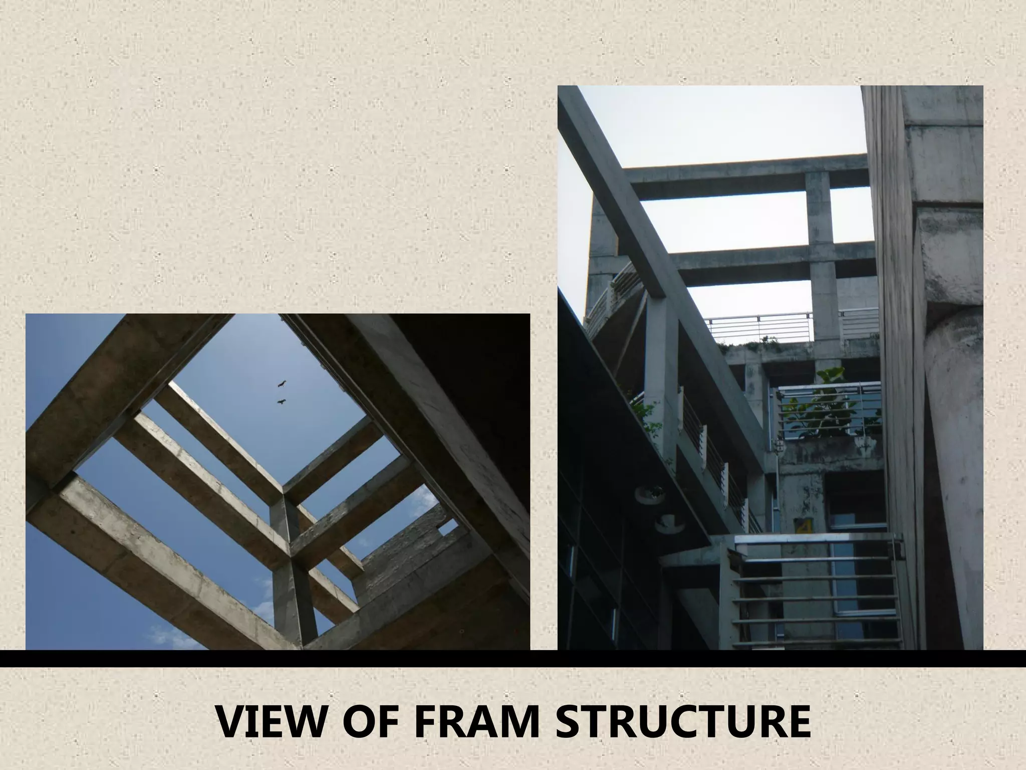
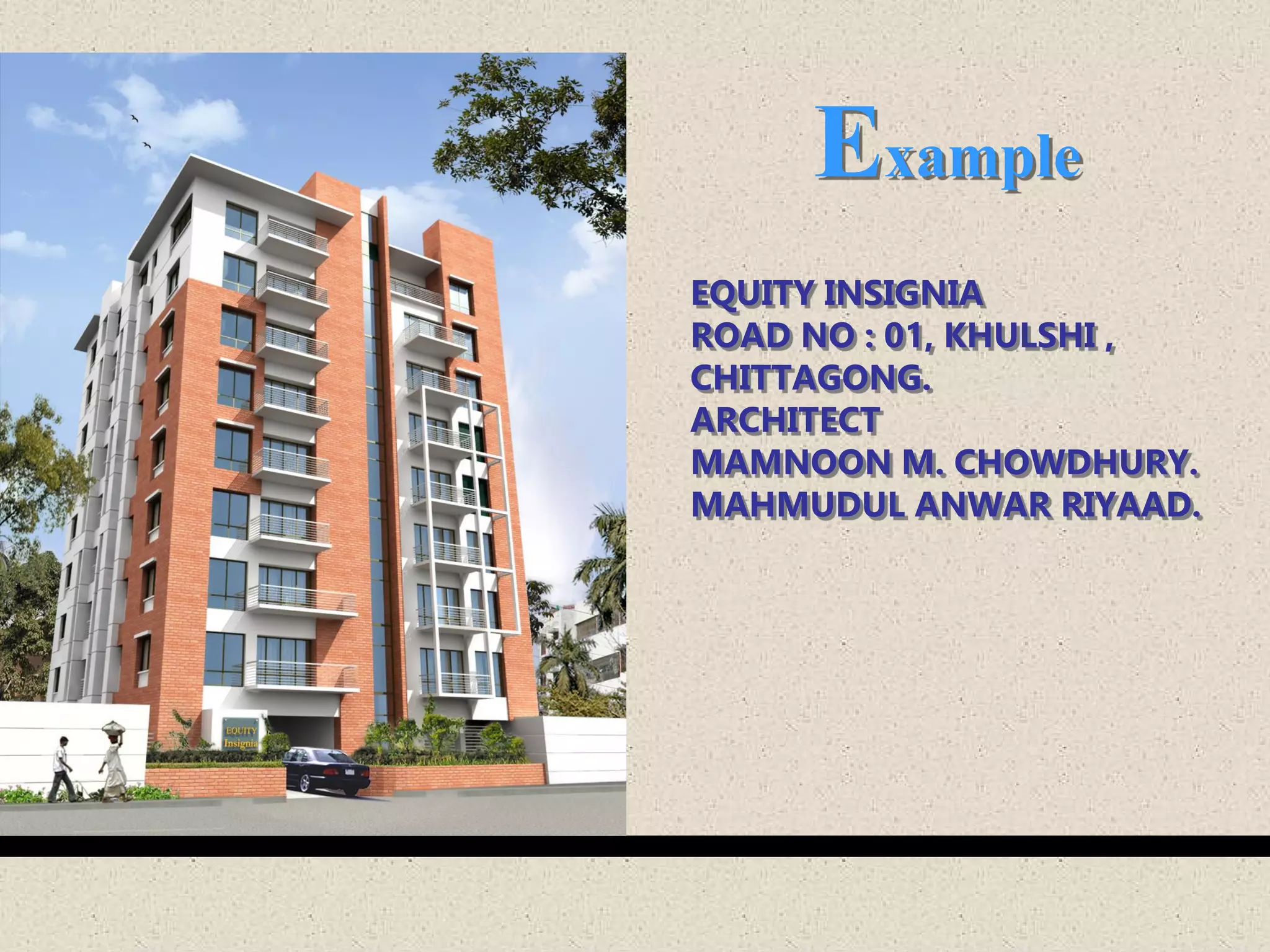
Presents real-life applications and architectural examples of post-lintel structures.
Presents real-life applications and architectural examples of post-lintel structures.
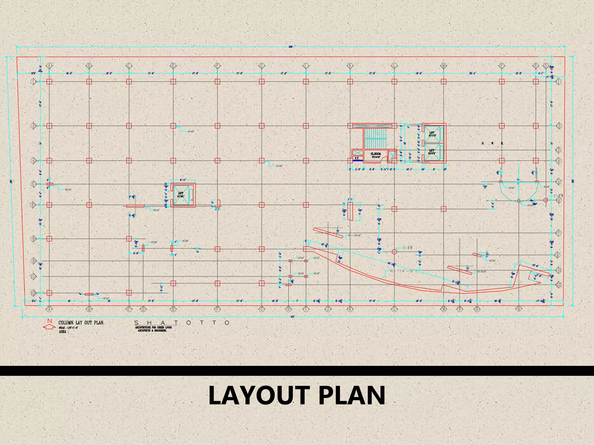
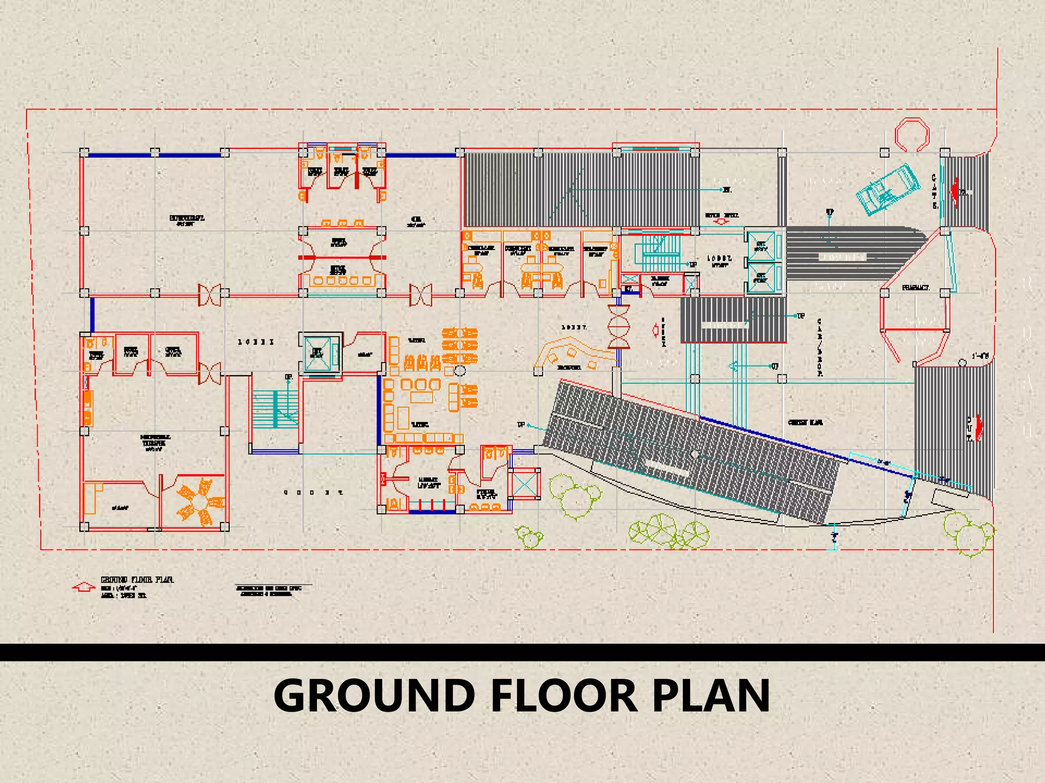
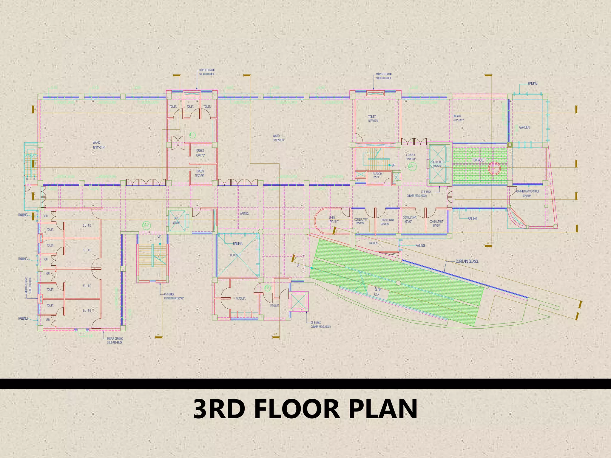
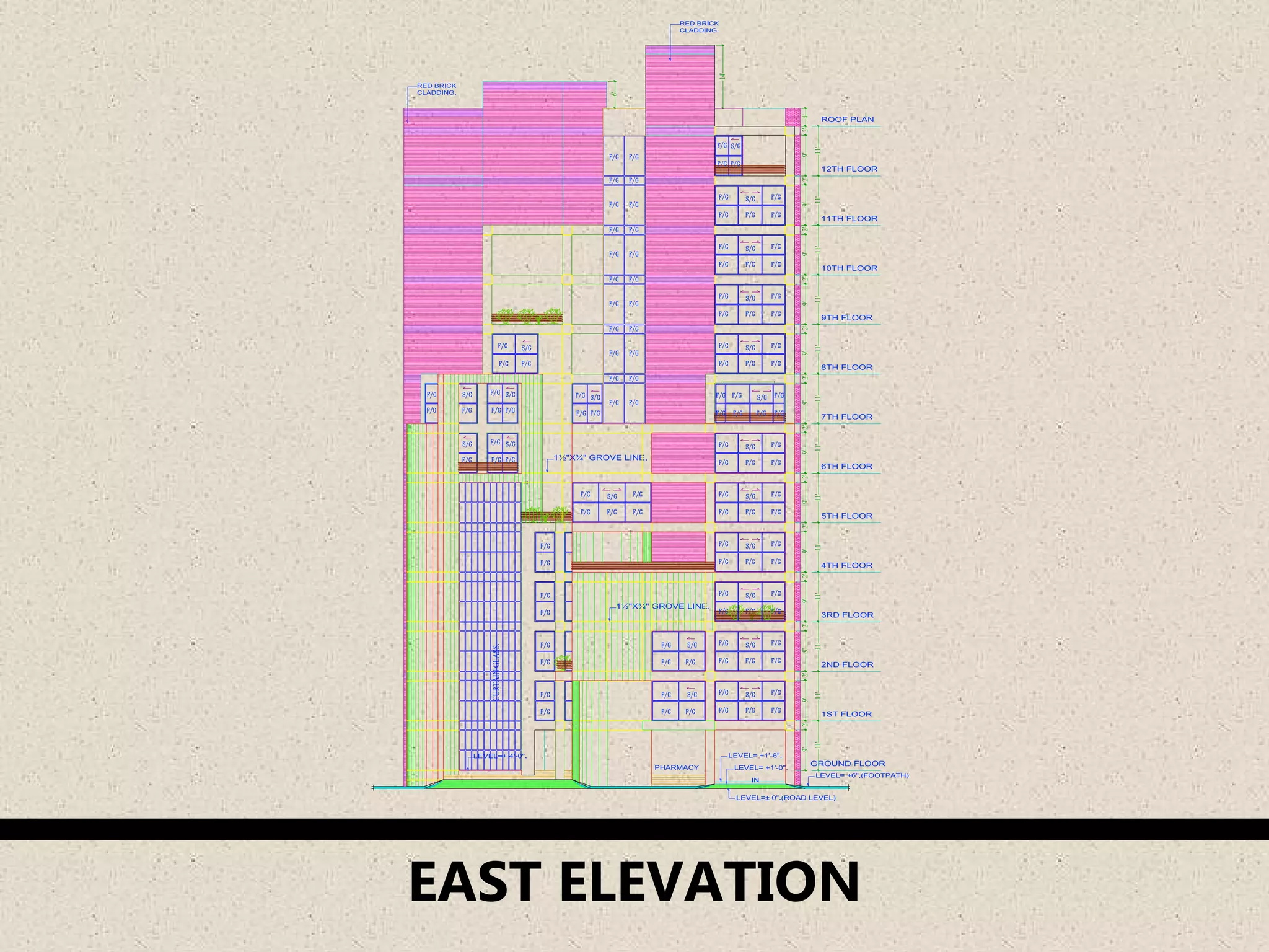
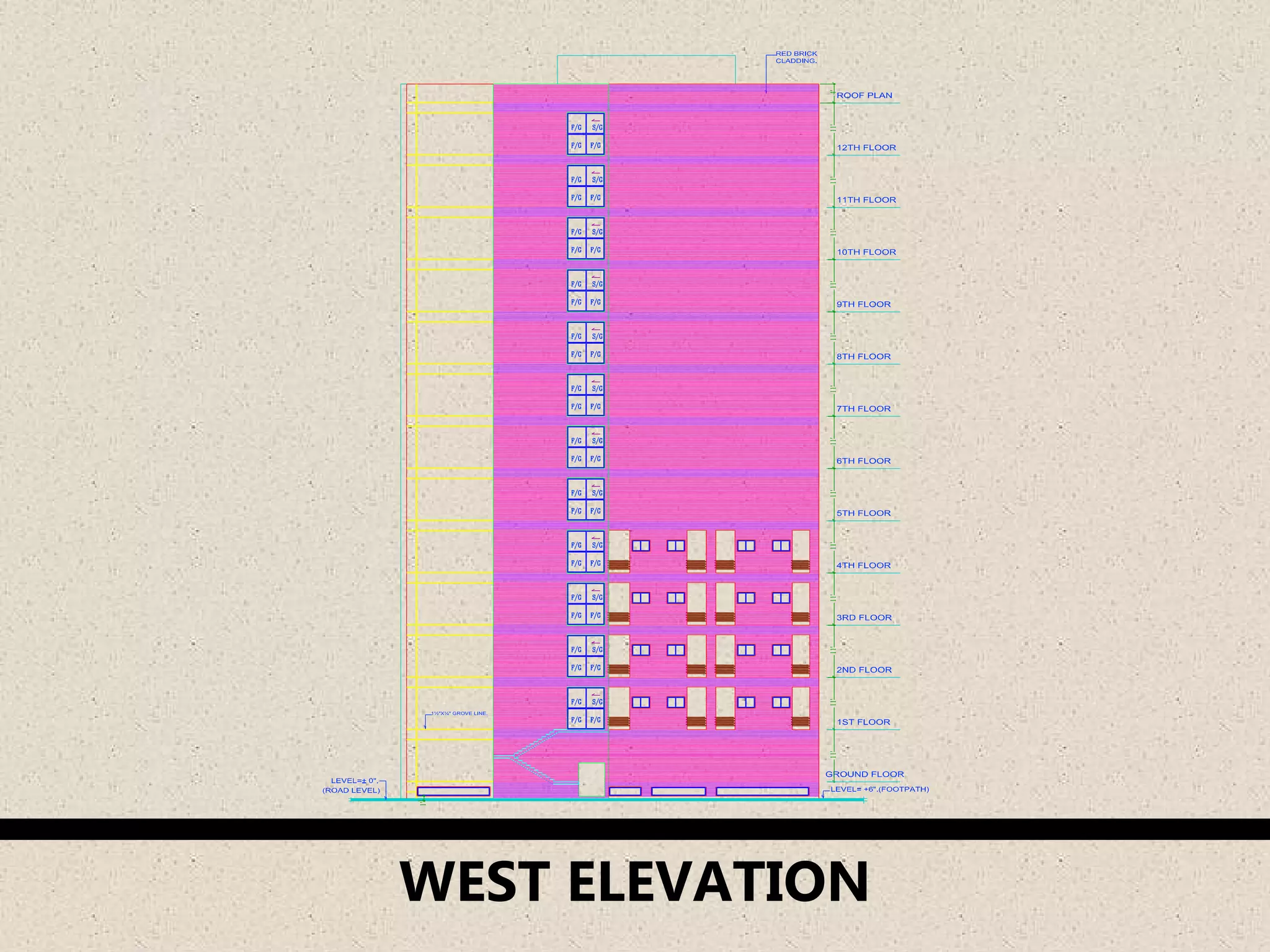
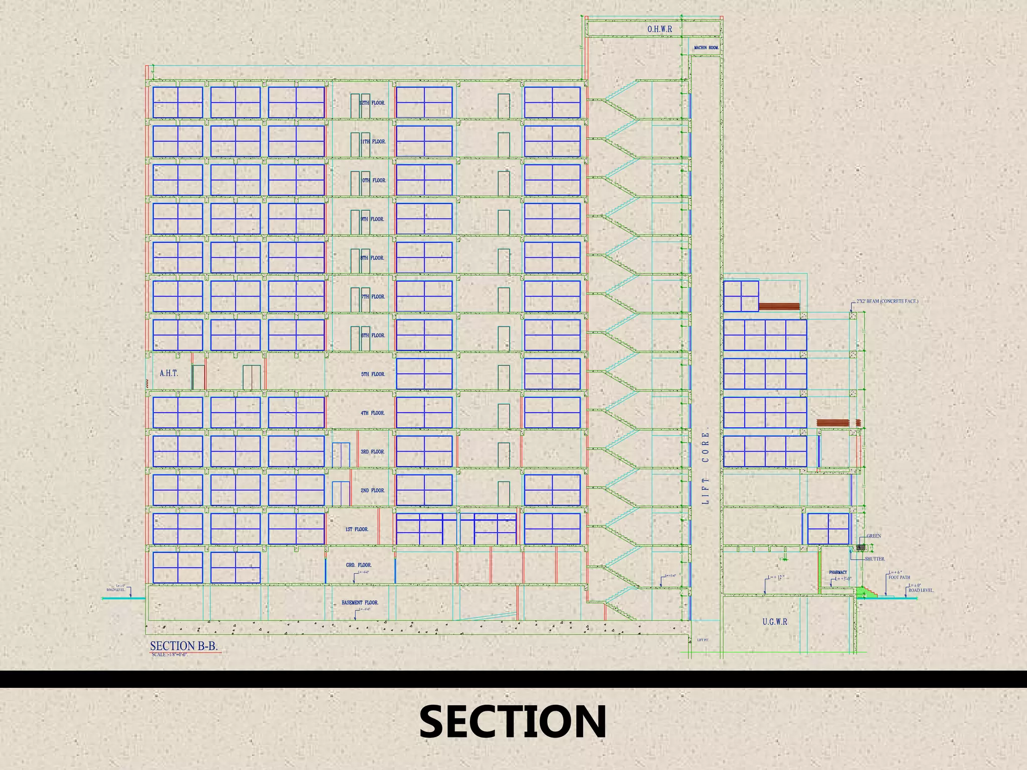
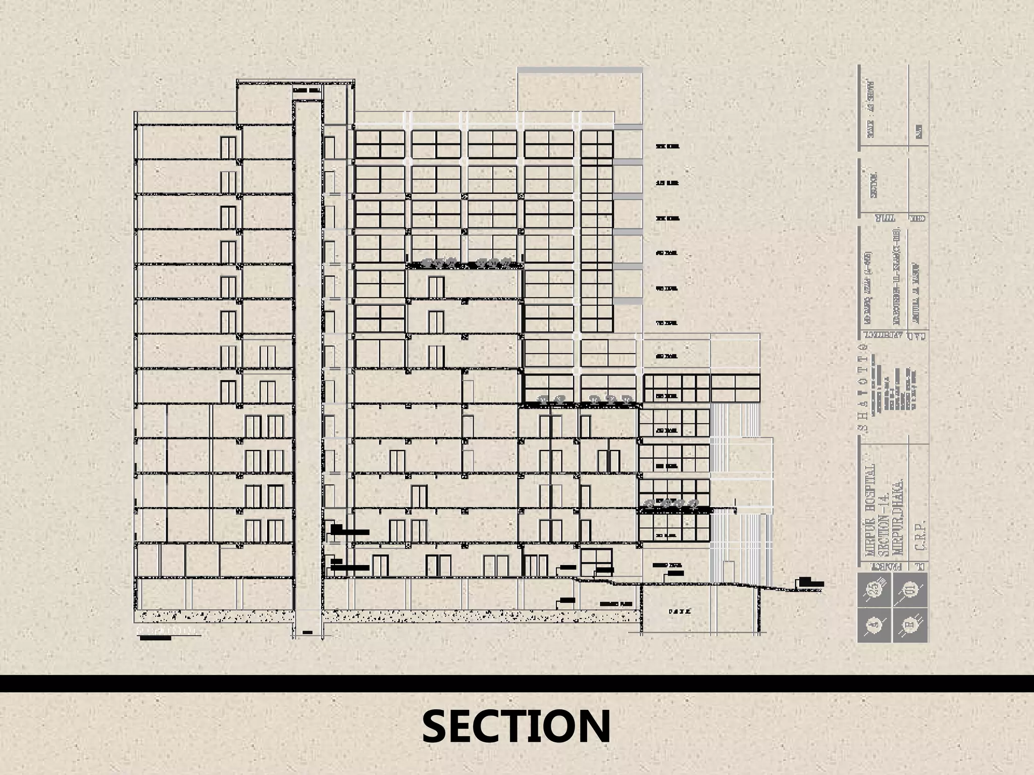
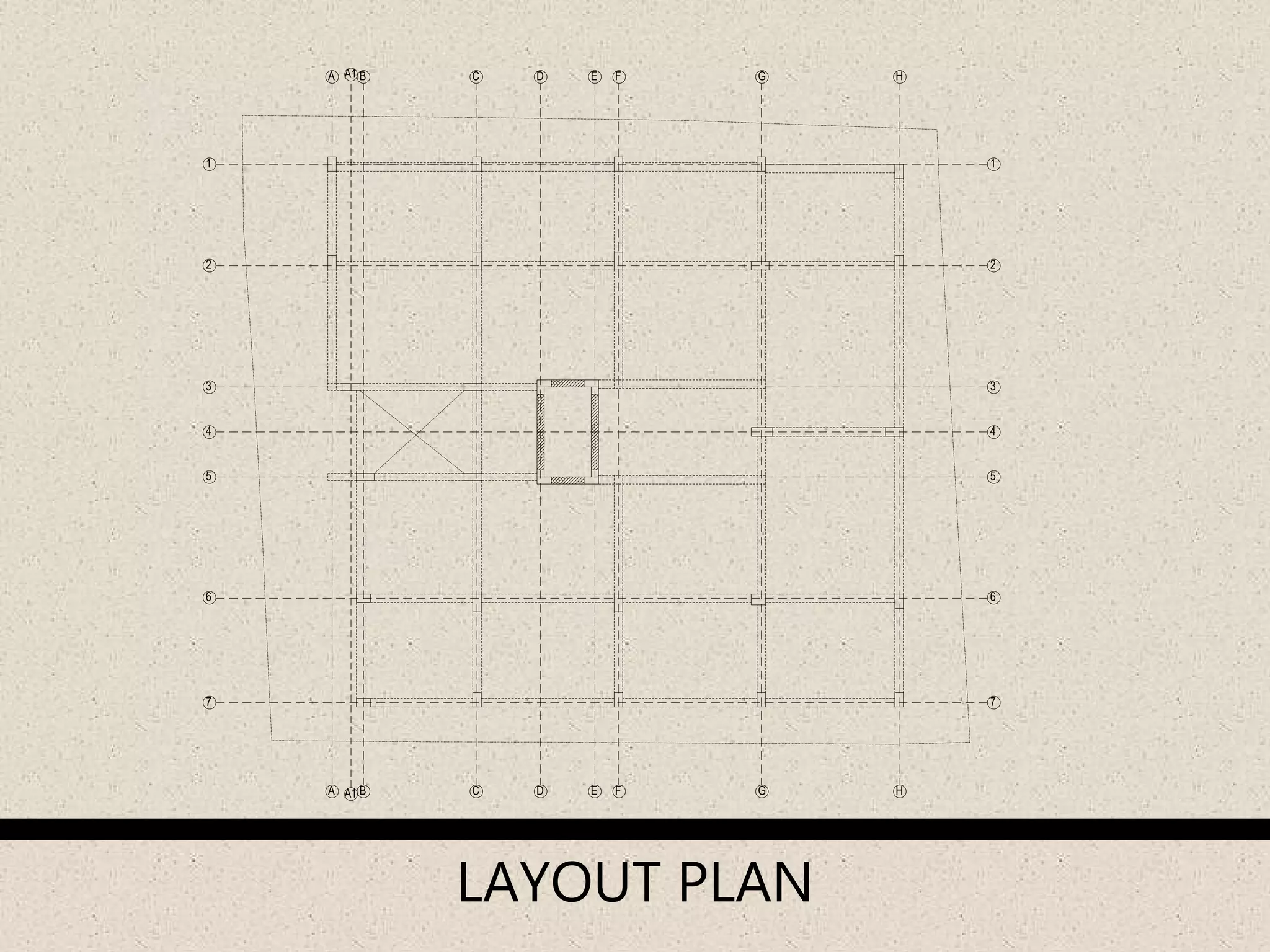
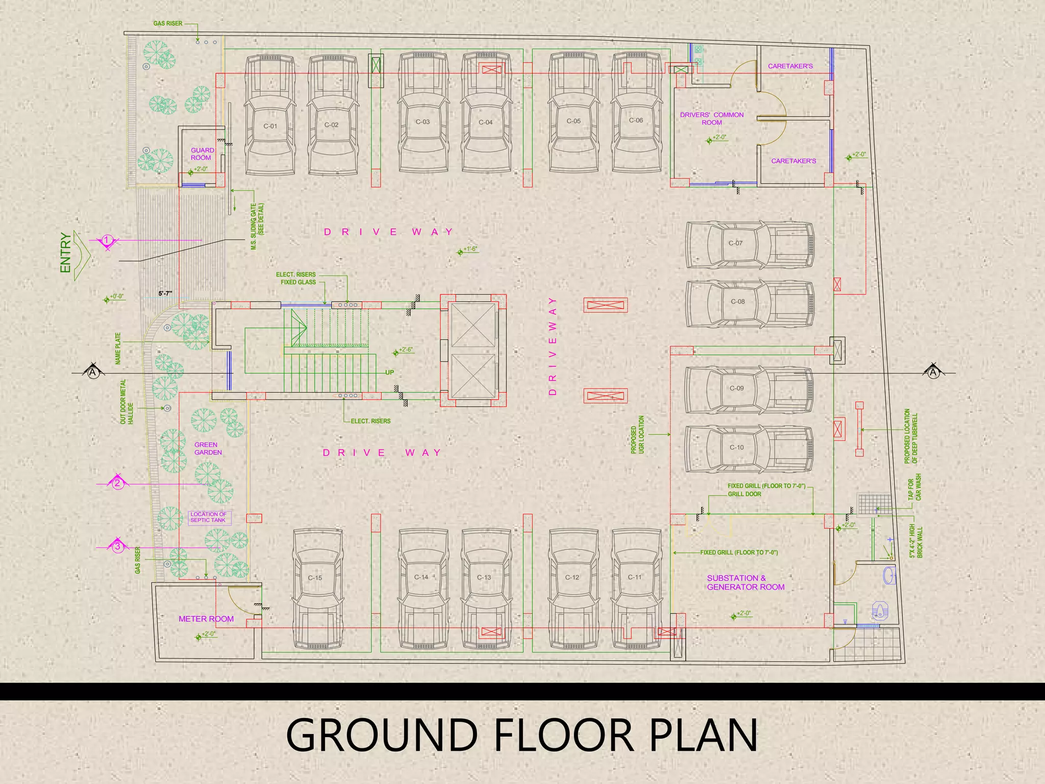
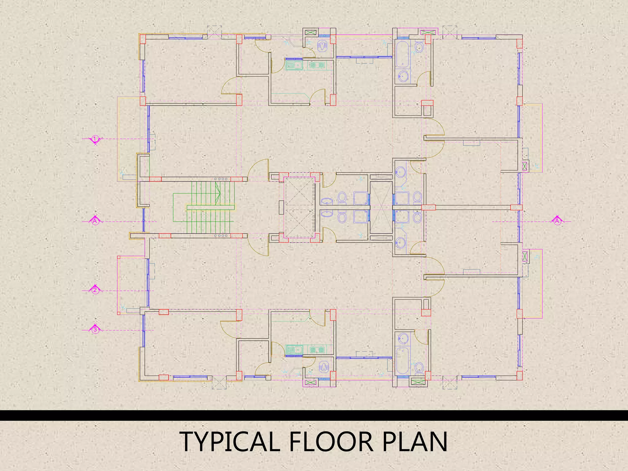
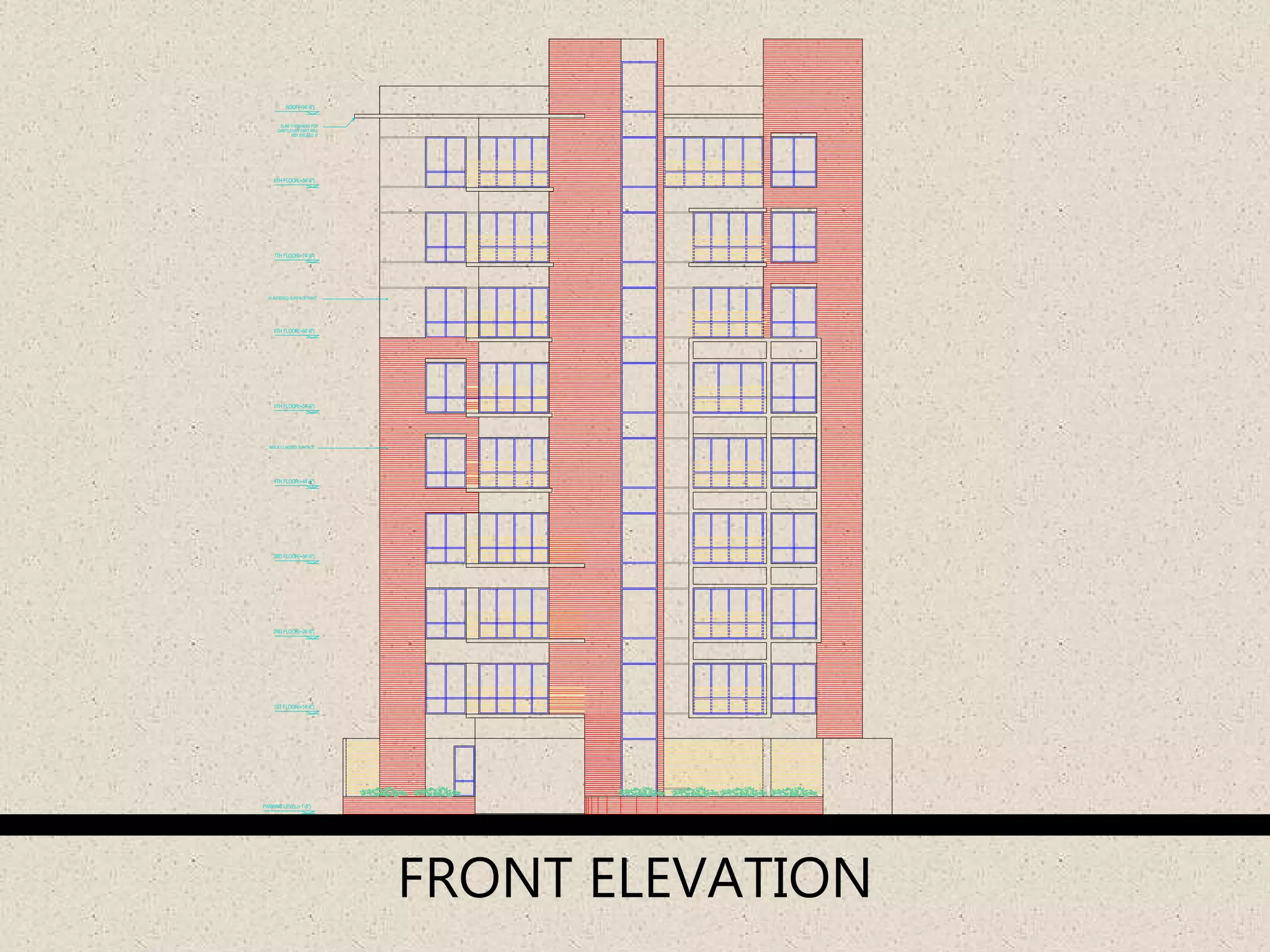
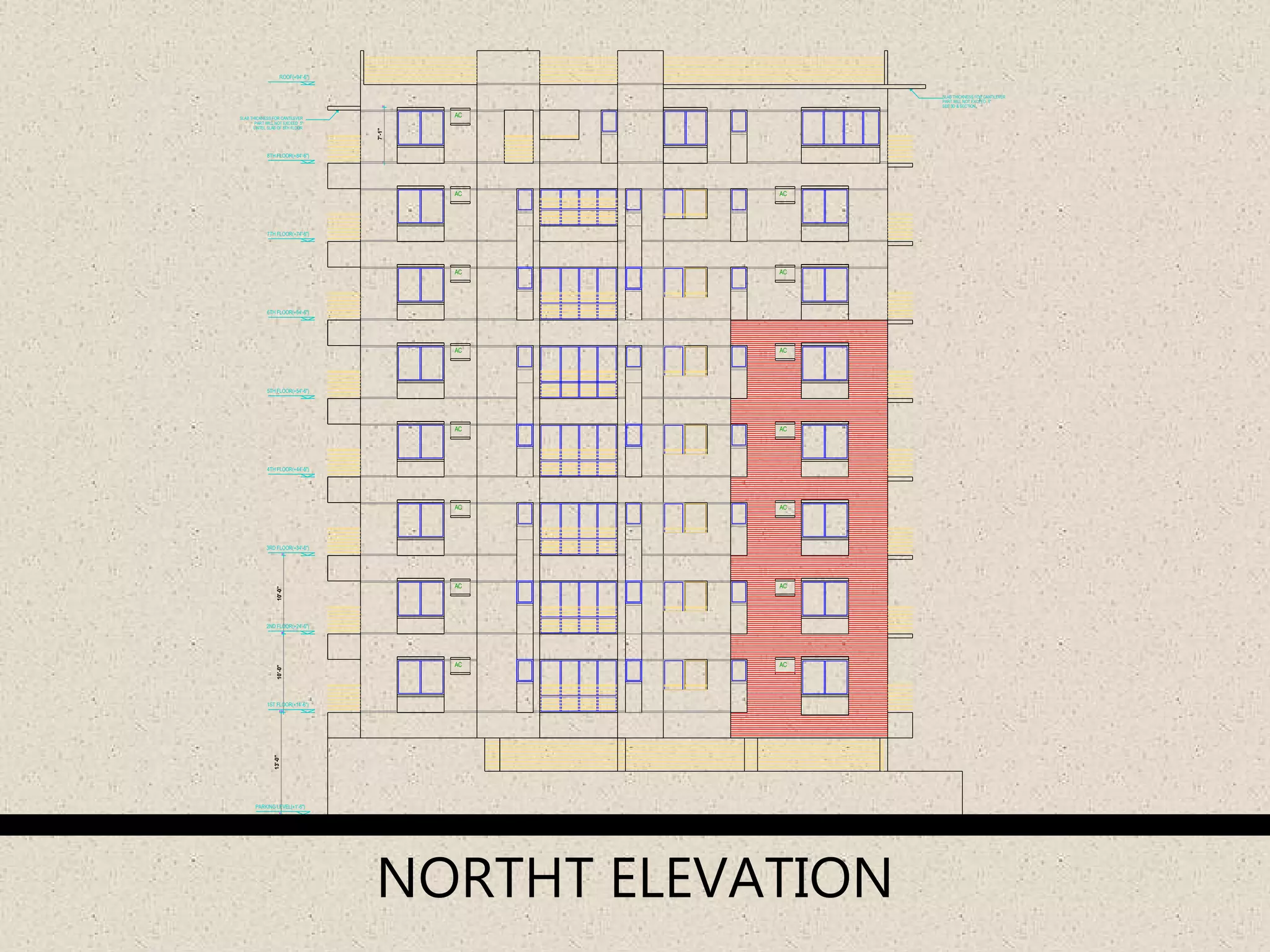
Illustrations of various plans for different floors and sections of buildings using post-lintel structures.
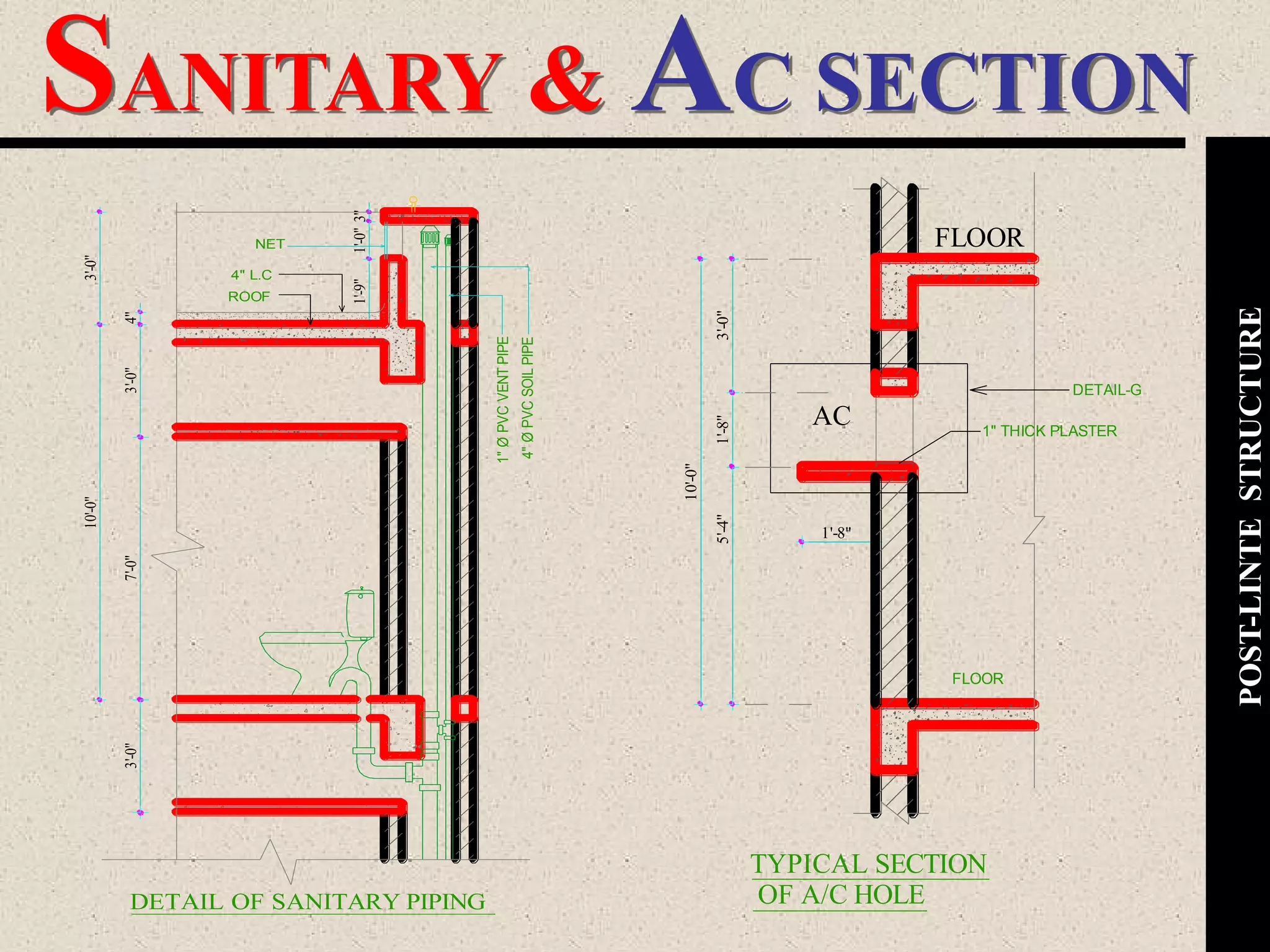
Final layout plans and specific section details for construction elements in the architecture discussed.
Final acknowledgments and thanks to the audience for participation.


![Soundtoys Mac v5.5.5.0 Crack for MacOS Full Version [Latest] pptx](https://cdn.slidesharecdn.com/ss_thumbnails/softwareoverview-251207193711-91d8ae6b-thumbnail.jpg?width=640&height=640&fit=bounds)

![Wondershare Filmora 15.0.11 Crack for Mac Key Full Download [Latest] pptx](https://cdn.slidesharecdn.com/ss_thumbnails/software-251207184836-1d16ba16-thumbnail.jpg?width=640&height=640&fit=bounds)

![iStat Menus 7.20 Crack for MacOS 2026 Full Version [Latest] pptx](https://cdn.slidesharecdn.com/ss_thumbnails/softwareoverview-251207191544-22b737dc-thumbnail.jpg?width=640&height=640&fit=bounds)


![PowerISO 9.2 Mac Crack + Serial Key Free Download 2026 [Latest] Software.pptx](https://cdn.slidesharecdn.com/ss_thumbnails/software-251207185653-5d5700e6-thumbnail.jpg?width=640&height=640&fit=bounds)


![Driver Easy Pro Key 7.1.0.2641 Full Mac Crack Free Activated Download [2026]....](https://cdn.slidesharecdn.com/ss_thumbnails/software-251207185324-b2fb71b4-thumbnail.jpg?width=640&height=640&fit=bounds)


