Downloaded 360 times
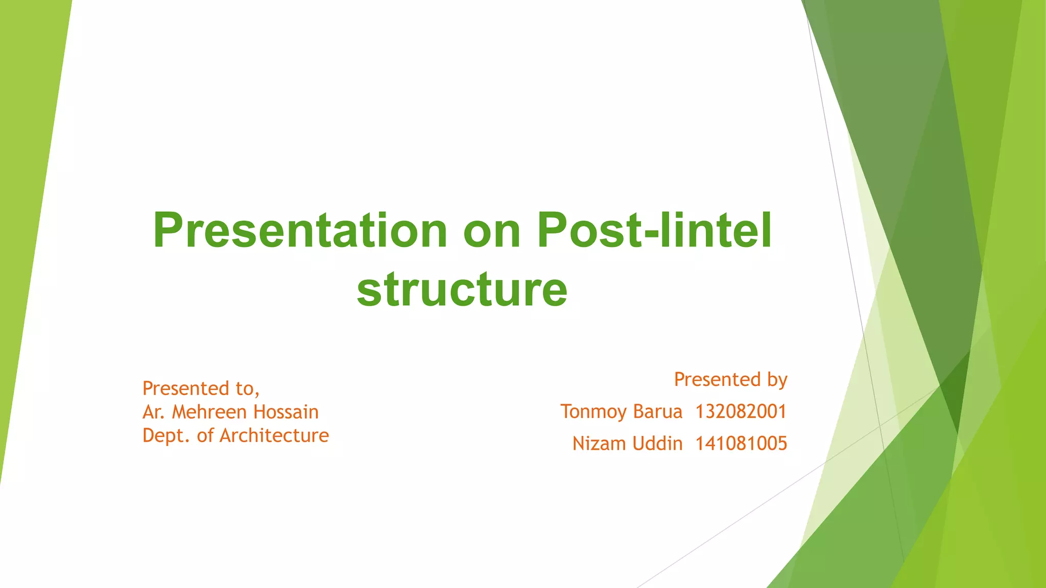
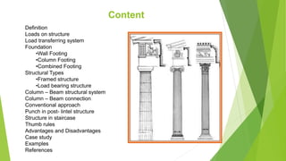


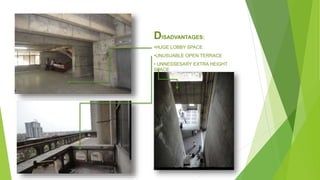
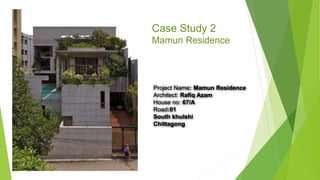
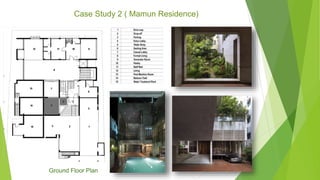
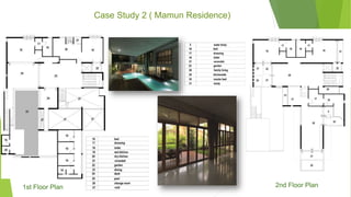
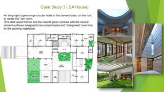


The presentation by Tonmoy Barua and Nizam Uddin explores post-lintel structures, outlining fundamental concepts such as load types, structural systems including framed and load-bearing structures, and various foundation types. They detail key components such as columns, beams, and their configurations, along with advantages and disadvantages of using post-lintel systems in construction. Case studies illustrate practical applications, showcasing their functionality and aesthetic benefits in architectural design.


