
Recommended
More Related Content
What's hot
What's hot (20)
Viewers also liked
Viewers also liked (17)
Similar to Advad.Ind.Const.Tech. Batch -3
Similar to Advad.Ind.Const.Tech. Batch -3 (20)
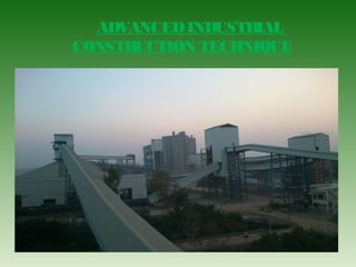
Advad.Ind.Const.Tech. Batch -3
- 2. Presented by PRASANTH KUMAR DASU M.N.SIRISHA M.T.SULEKHA T.JAYA RAM Under the guidance of Naomi Nischala.
- 3. WHAT IS FLY ASH SILO: The fly ash silo is a massive structure in cement plants, which is used to store the fly ash in that structure to add the required amount of fly ash for cement manufacturing by using conveyers. Its is Generally circular in shape. Capacity of this silo is 40,000 tons. OBJECTIVE: CONTRUCTION OF FLY ASH SILO
- 4. CONSTRUCTION OF FLY ASH SILO BY USING ADVANCED CONSTRUCTION TECHNIQUE’S : PILE FOUNDATION SLIP FORM TECHNIQUE POST TENSIONING
- 5. WHAT IS PILE FOUNDATION: Deep foundations are employed when the soil strata immediately beneath the structure are not capable of supporting the load with tolerable settlement or adequate safety against any failure. Pile foundations are relatively long, slender members that are driven into the ground or cast-in- situ.
- 6. TYPE OF FUNDATION USED PILE FOUNDATION.
- 7. A VISUAL ABOUT PILE FONDATION:
- 8. Bored cast in situ pile: Only concrete piles can be cast-in-situ. piles can be cast-in-situ. Holes are drilled and these are filled with concrete. These may be straight-bored piles or may be ‘under-reamed’ with one or more bulbs at intervals. Reinforcements may be used according to the requirements. Type of pile:
- 9. No. of piles 65 Nos. LAYOUT OF PILES
- 10. DETAIL OF PILE FOUNDATION: Specifications followed as per IS:456-2000 Diameter of pile- 1.0 meter. Reinforcement used 25 dia. 8 nos. Stirrup of 12mm dia spacing 200 mm c/c. Depth of pile 23.5 meters.
- 11. Specifications followed as per IS:456-2000 Concrete grade used is M25 (1:1:2) Grade of steel.Fe 500. Cover maintained for main reinforcement 75 mm. Pile is to be embeded into the hard strata atleast 150 to 300mm .
- 12. SLIP FORM: Its a Moving formwork. A Continuously Moving form Moving at such a speed , when concrete is completed its initial setting time and after getting hardened. It will withstand lateral pressure caused by jack rod, wind pressure etc. TYPE OF FORM WORK
- 13. PRINCIPLE OF SLIPFORM SLIPFORM MEANS A CONTINUOUSLY MOVING FORM MOVING AT SUCH A SPEED BY USING THE HYDRAULIC PRESSURE GIVEN GRADUALLY TO THE FORM WORK UP TO DESIRED HEIGHT.THE WHOLE FORM WORK WILL BE MOVED BY SUPPORTING ON CLIMBING ROD OR JACK ROD.
- 14. TYPES OF SLIPFORM 1. STRAIGHT SLIPFORM. 2. TAPERED SLIPFORM. 3. SLIPFORM FOR SPECIAL APPLICATIONS.
- 15. Straight slipform Silos Chimneys (cylindrical) Water towers Central core for office blocks Columns Tapered slipform Chimneys (conical) Ventilation stacks APPLICATION OF SLIPFORM
- 17. WORKABILITY REQUIRED A. Easy compaction B. To cover and protect the reinforcement. C. To have less friction on formwork shutters. • A film of mortar is created by compaction at the contact with the form panel. • This mortar film avoids micro - cracks during slipform lifting. D. Provide smooth surface to wall.
- 18. THE ABOVE FACTORS DEPEND ON - QUALITY OF CEMENT. - NATURE & SHAPE OF AGGREGATES. - WATER CEMENT RATIO - COMPACTION. - HARDENING TEMPERATURE. MINIMUM CONCRETE STRENGTH FOR SLIPFORM
- 19. COMPONENT PARTS OF SLIPFORM
- 20. A VISUAL ABOUT SLIP FORM
- 21. Slipform assembly at (-)2.00m level
- 24. Exposed concrete surface finishing from slipform platform
- 26. AT 30 METERS HEIGHT
- 27. MORE DETAILS ABOUT SILO DIAMETER OF SILO 22 METERS. WALL THICKNESS OF SILO 800 MM UP TO 16.5 METERS. 16.5 TO 57 MTS 350 MM THICK. INSERT PLATES FOR EQUIPMENTS AND CONVEYORS FIXING.
- 28. • Accuracy • Monolithic construction • Lends itself to almost any shape in plan • High quality surface finish • Saves lot of workmanship. • Saves staging materials • Economical above a certain height. • Produces aesthetically pleasing structures ADVANTAGES OF SLIP FORM:
- 29. POST-TENSIONING Introduction What is post-tensioning? Post-tensioning- is a method of reinforcing (strengthening) concrete or other materials with high-strength steel strands called tendons.
- 30. O bje ctive : Concrete is very strong in compression but weak in tension, so as a tension resistant member we provide tendons for silo wall to strengthen the wall.
- 31. Structural elements that use post-tensioning: Many types of bridges Elevated slabs. Foundations. Walls and columns. Silos and chimneys.
- 33. Methods and Materials PT strand - ASTM A416 – 7-wire treated carbon steel – Min. TY (yield) = 52.74 kips – Min. TU (breaking) = 58.60 kips Anchors - ACI code – Guaranteed up to 95% of the breaking strength TU.
- 34. Method of post-tensioning. This is the hydraulic jack used for tensioning
- 35. GRO UTING EQUIPMENT Air Powered Grout Pump Pumps cement grout only, no sand. 32 Gallon Mixing Tank. Mixes up to 2 sacks of material at once and allows for grout to be pumped during mixing or mixed without pumping.
- 36. Detailed method of post-tensioning In slab-on-ground construction, unbonded tendons are typically prefabricated at a plant and delivered to the construction site, ready to install. The tendons are laid out in the forms in accordance with installation drawings that are given. After the concrete is placed and has reached its required strength, usually between 3000 and 3500 psi (“pounds per square inch”), the tendons are stressed and
- 37. The tendons, like rubber bands, want to return to their original length but are prevented from doing so by the anchorages. The fact the tendons are kept in a permanently stressed(elongated) state causes a compressive force to act on the concrete. The compression that results from the post- tensioning counteracts the tensile forces created by subsequent applied loading. This significantly increases the load- carrying capacity of the concrete.
- 38. Bonded post-tensioned concrete is the descriptive term for a method of applying compression after pouring concrete and the curing process (in situ). The concrete is cast around a plastic, steel or aluminium curved duct, to follow the area where otherwise tension would occur in the concrete element. A set of tendons are fished through the duct and the concrete is poured. Once the concrete has hardened, the tendons are tensioned by hydraulic jacks.
- 39. When the tendons have stretched sufficiently, according to the design specifications they are wedged in position and maintain tension after the jacks are removed, transferring pressure to the concrete. The duct is then grouted with cement to protect the tendons from corrosion. This method is commonly used to create homogeneity in load transmission.
- 40. ADVANTAGES OF POST-TENSIONINGADVANTAGES OF POST-TENSIONING • Longer clear spansLonger clear spans • Thinner slabsThinner slabs • Lesser floor-to-floor heightsLesser floor-to-floor heights • Shorter building heightShorter building height • Lesser weightLesser weight • Improved seismic performanceImproved seismic performance • Faster construction cycleFaster construction cycle
- 41. Post-tensioned structures can be designed to have minimal deflection and cracking, even under full load. Post-tensioning tendons, on the other hand, are considered “active” reinforcing.
- 42. DISADVANTAGES OFDISADVANTAGES OF POST-TENSIONINGPOST-TENSIONING The main disadvantage over post- tensioning is the fact that a cable can distress itself and burst out of the slab if damaged (such as during repair on the slab).
- 43. THANKYOU
- 44. ANY QUERIE’S?