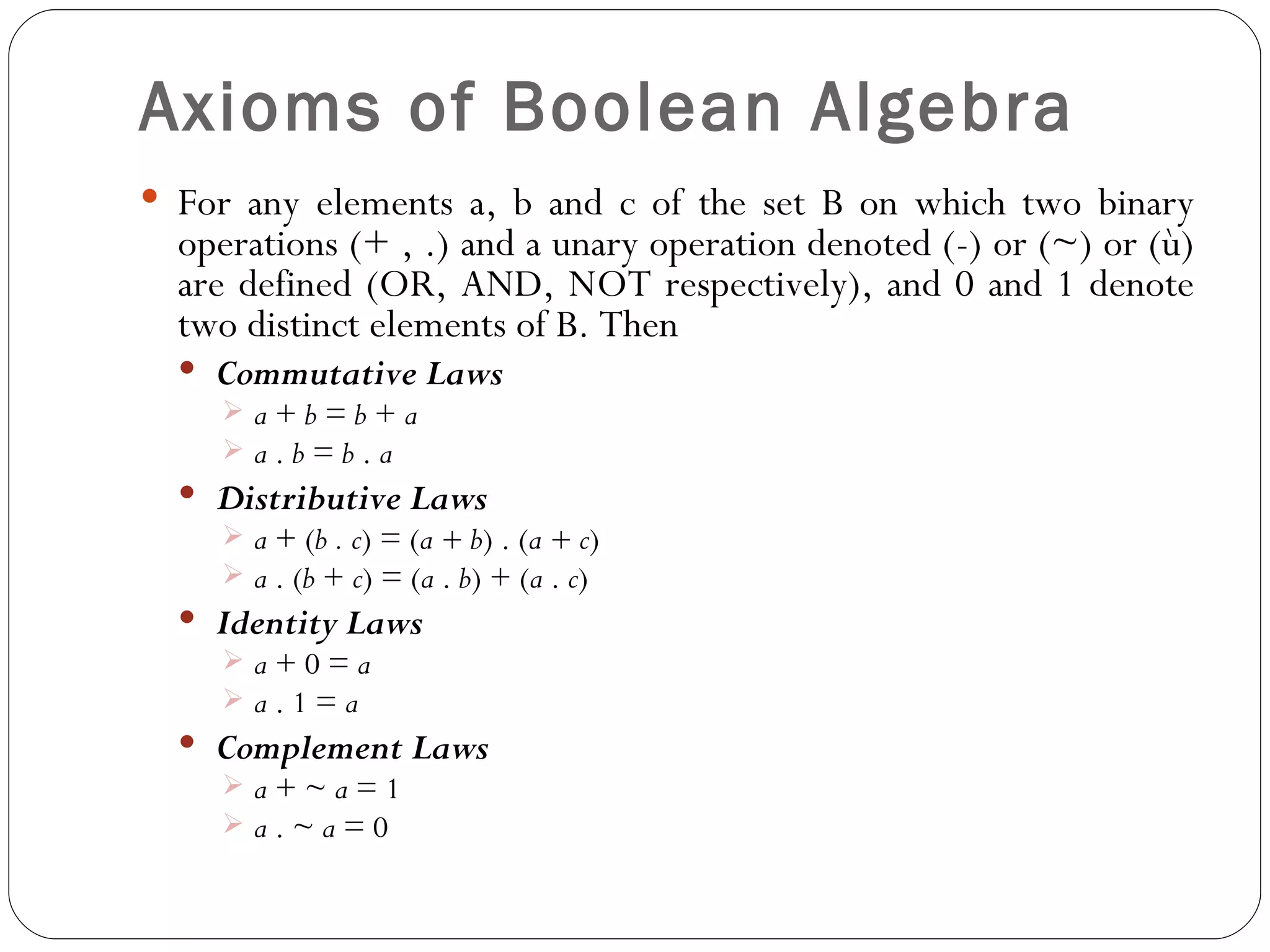
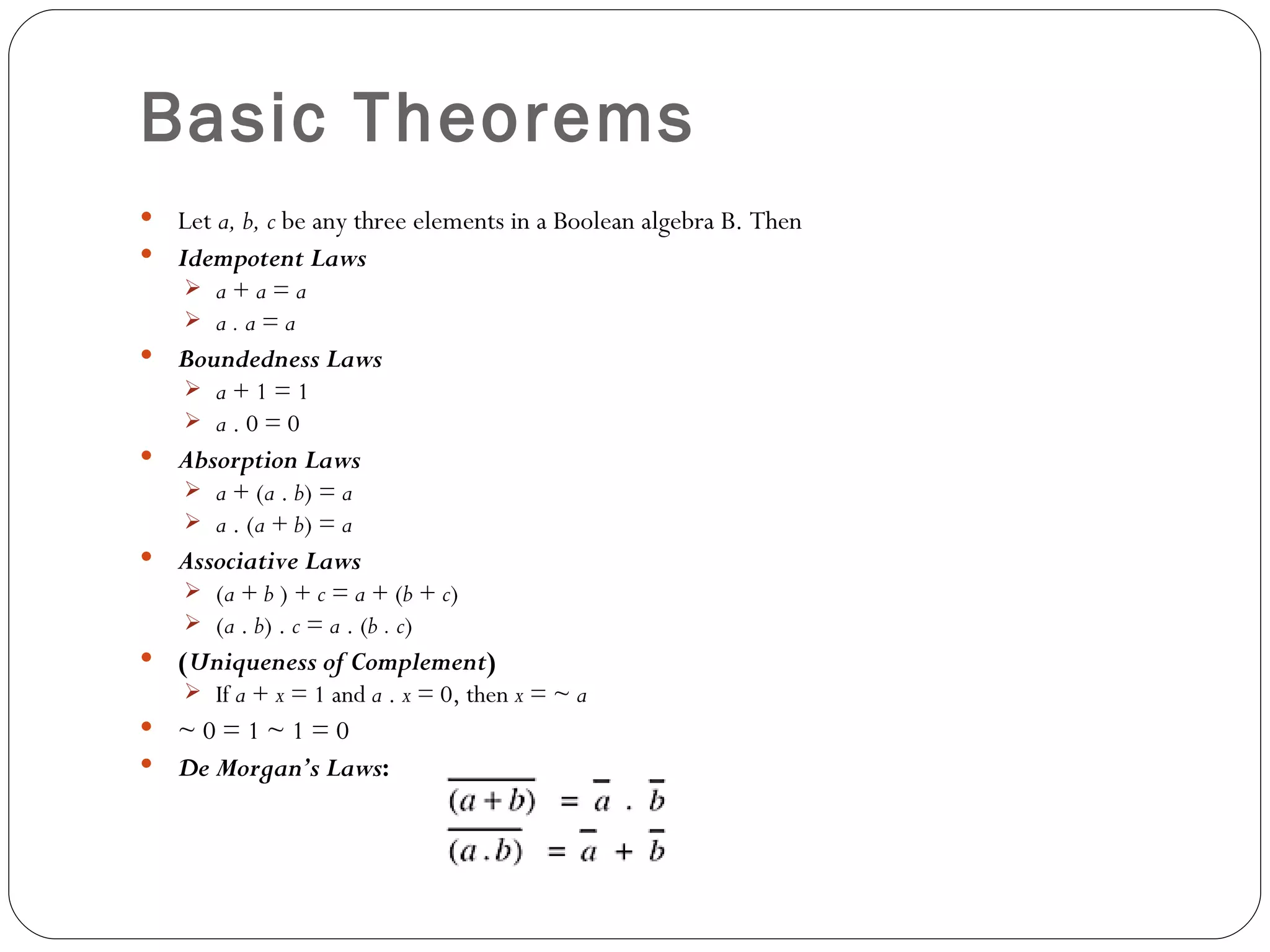
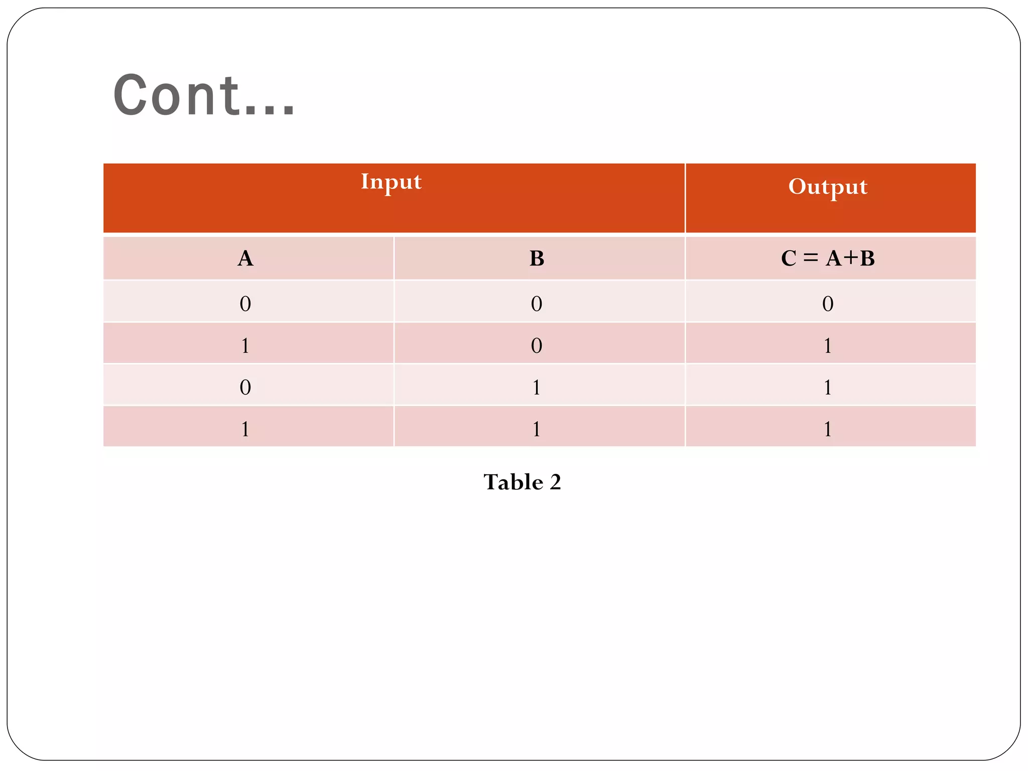
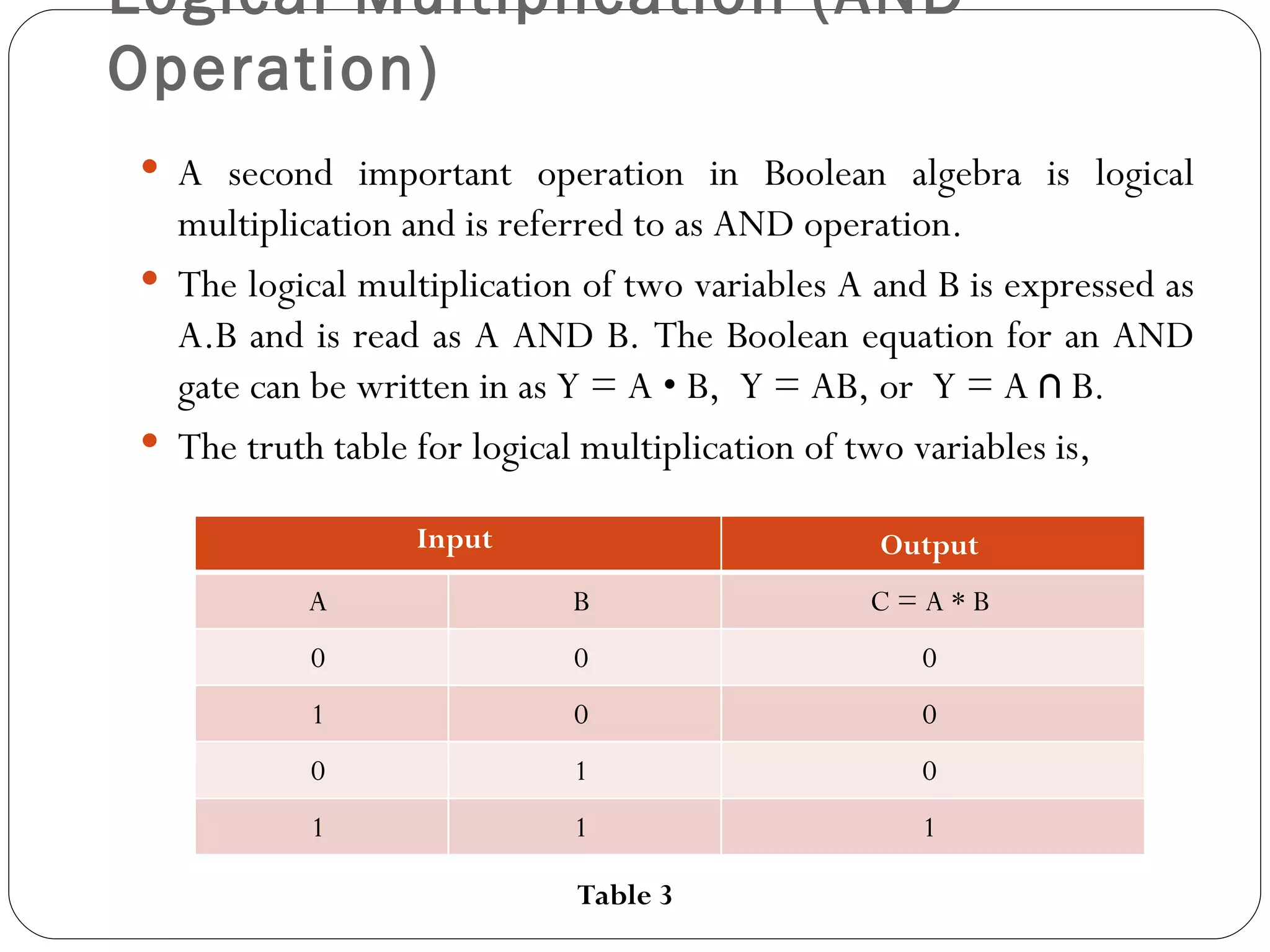
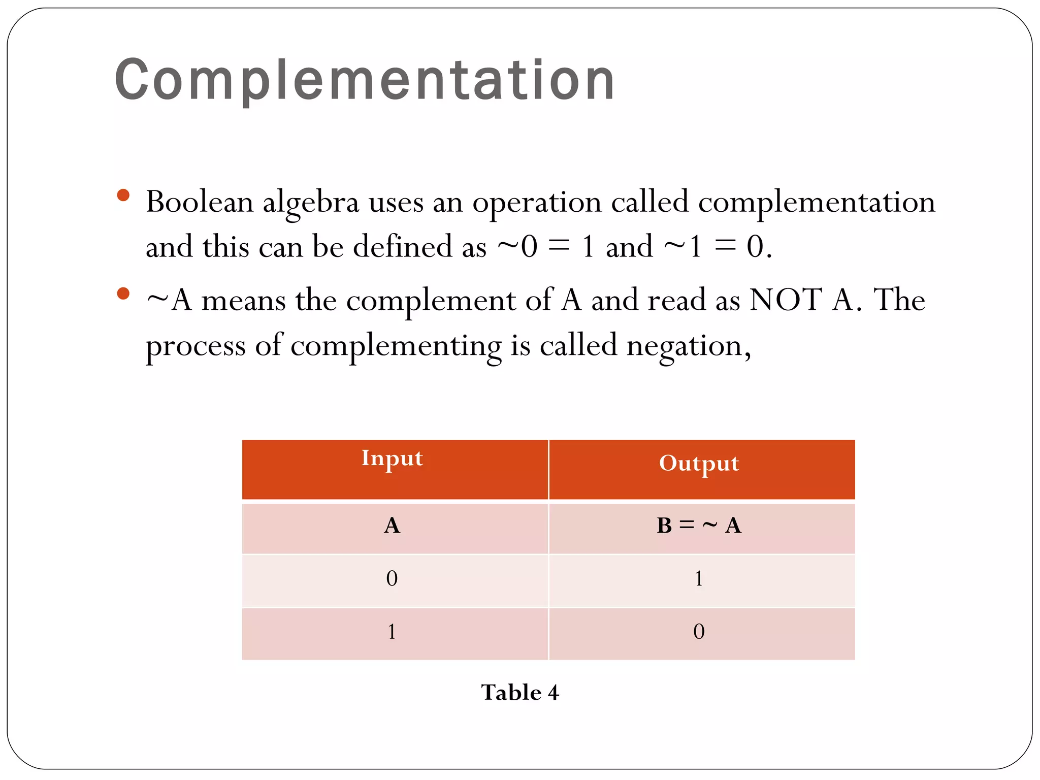
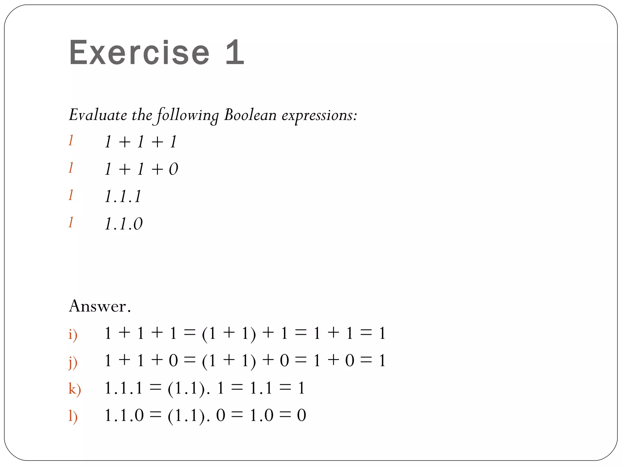
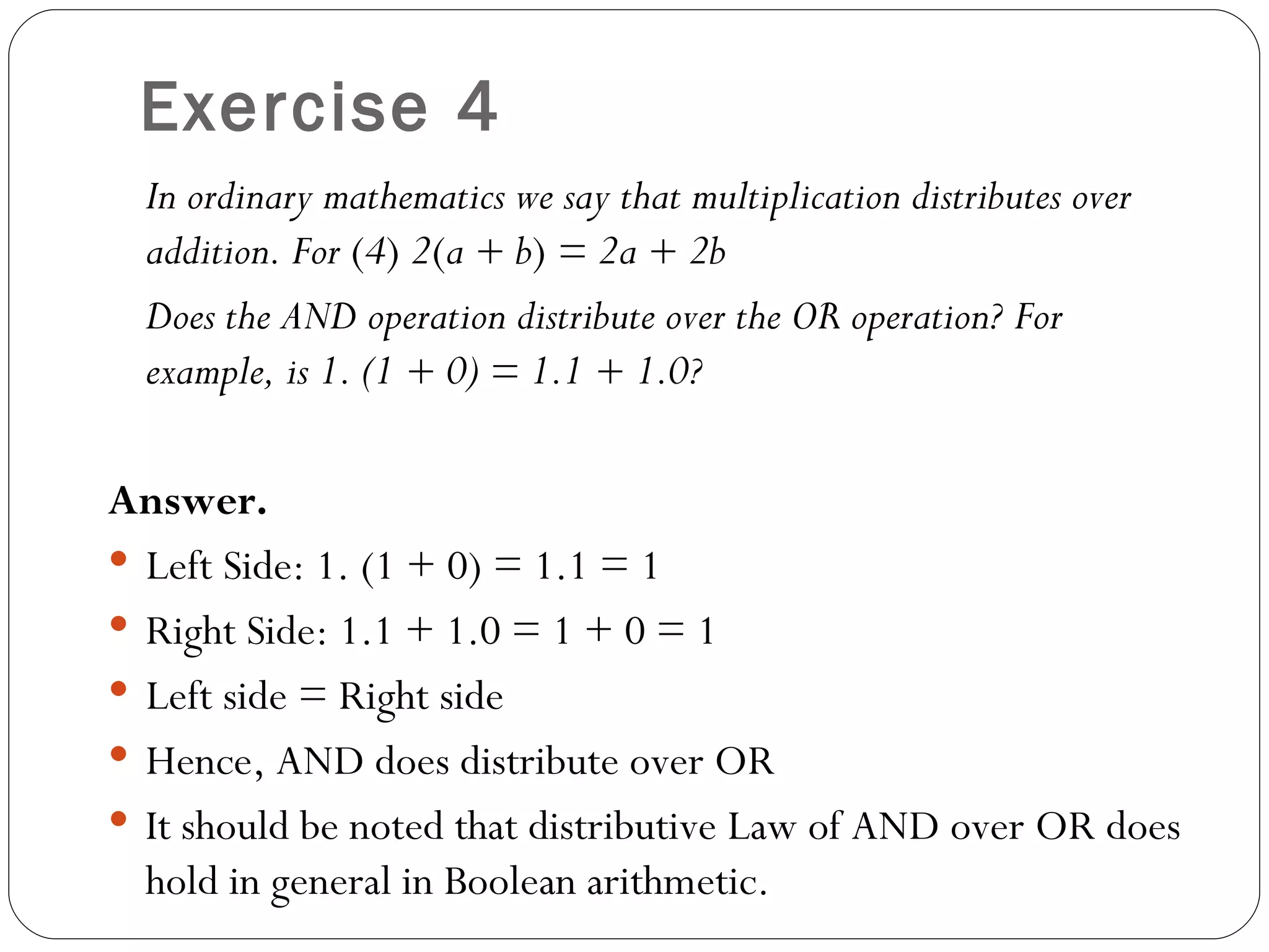
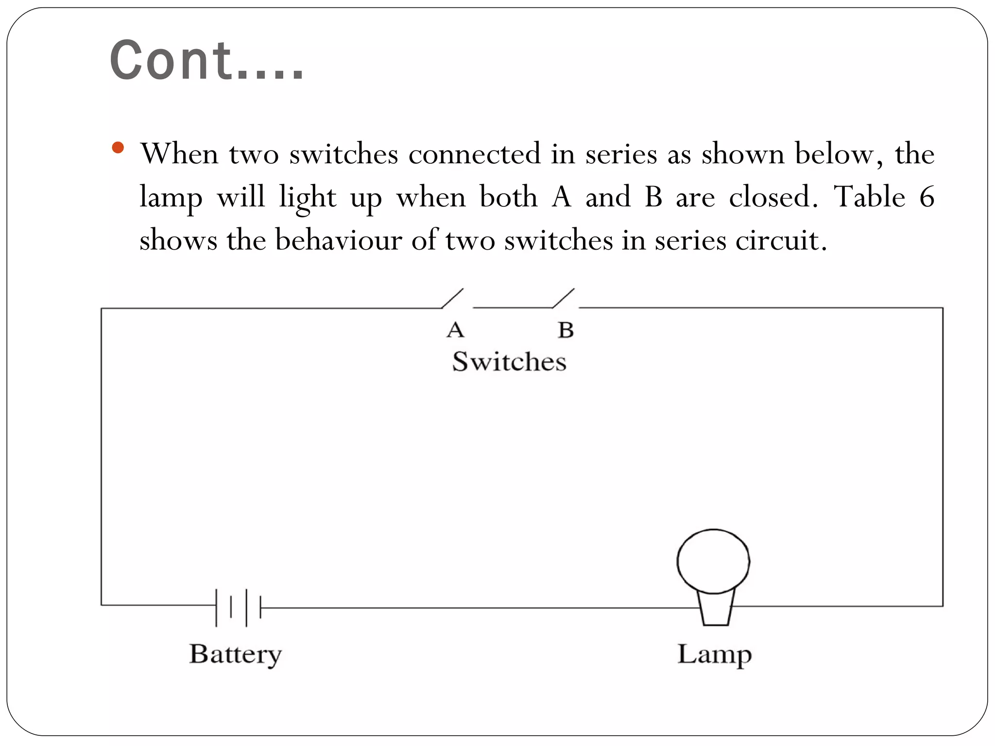
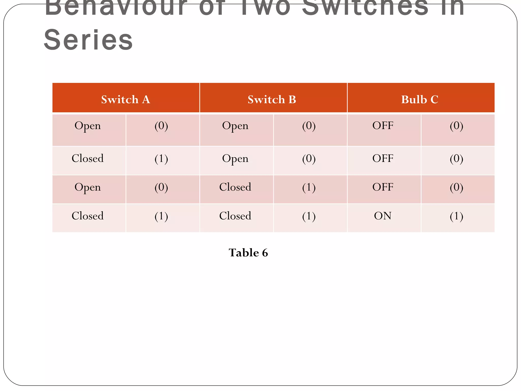
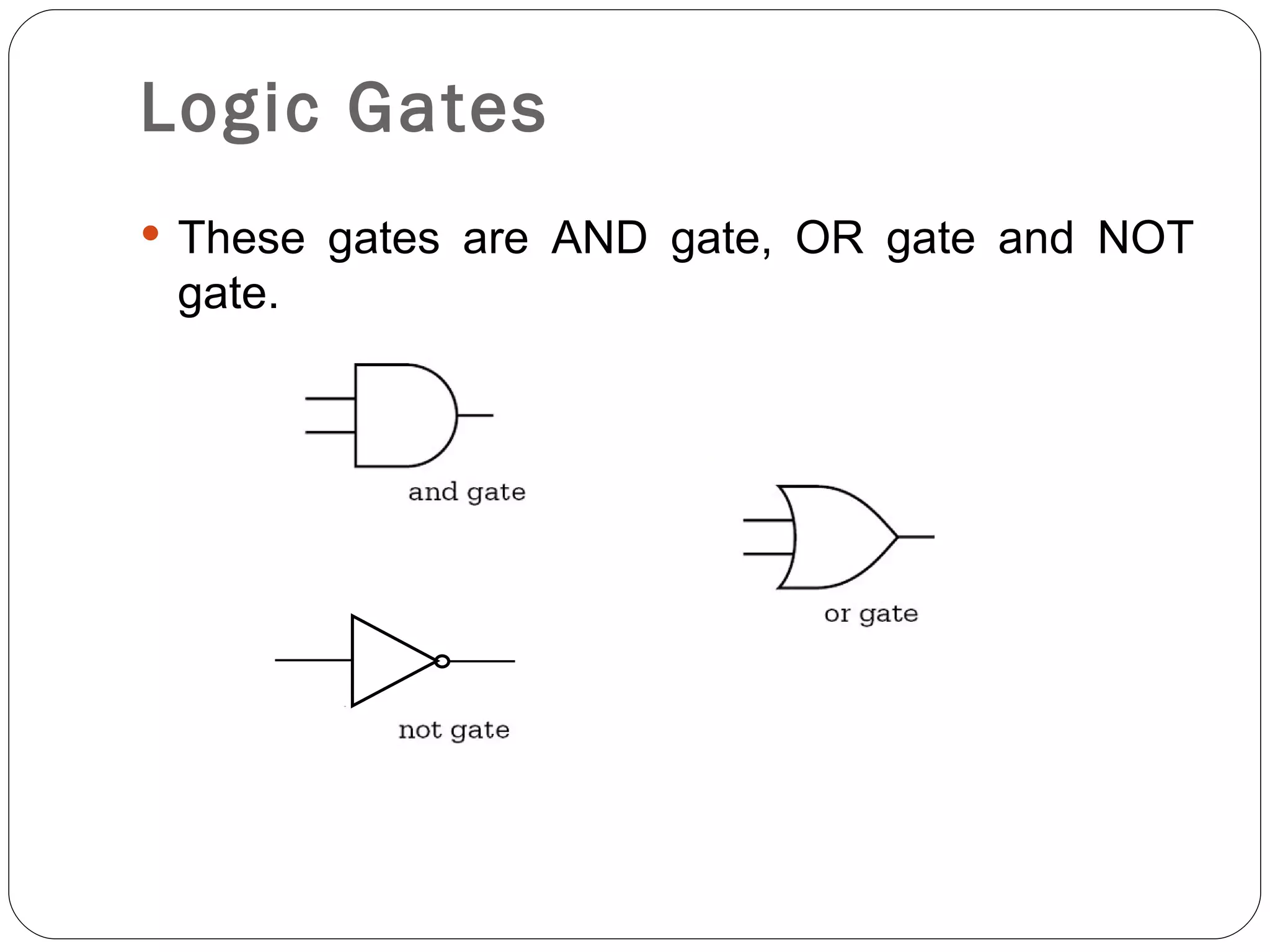
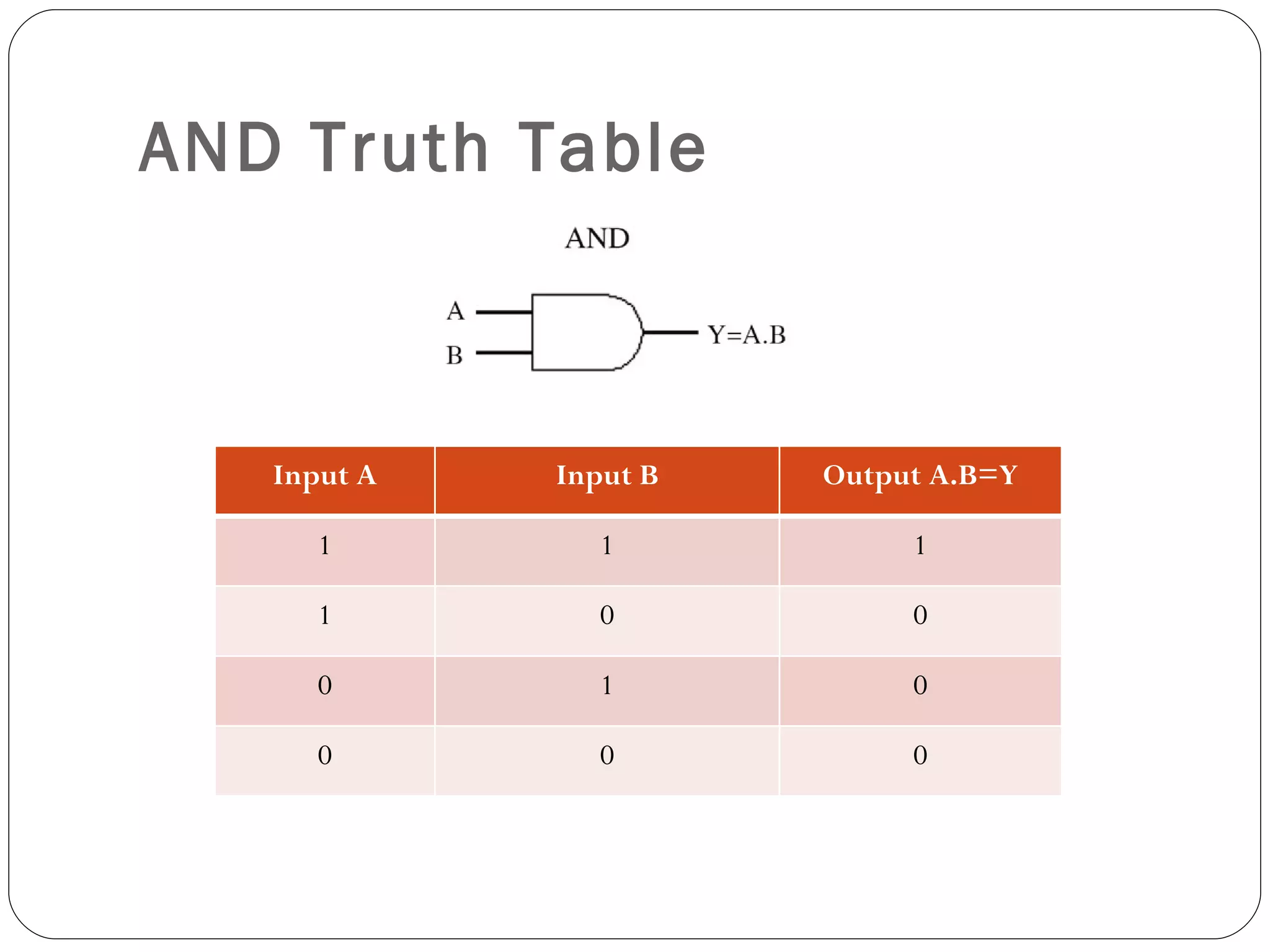
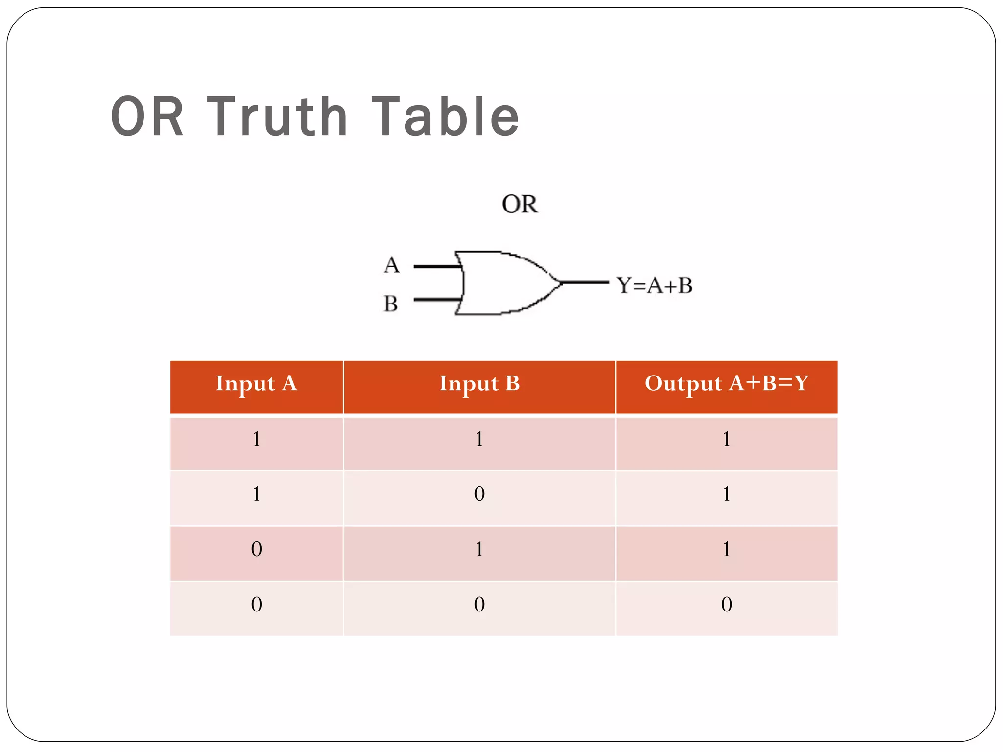
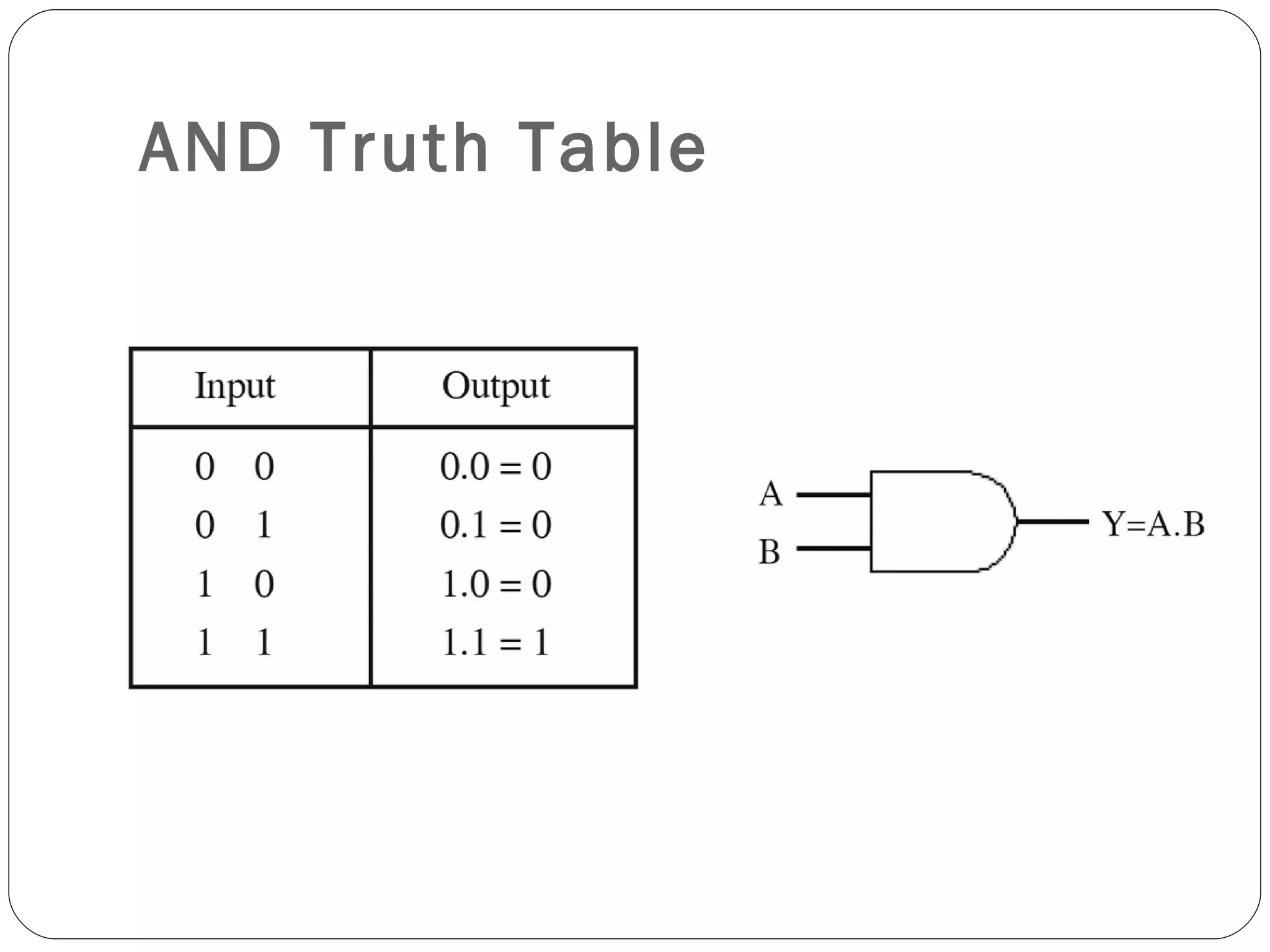
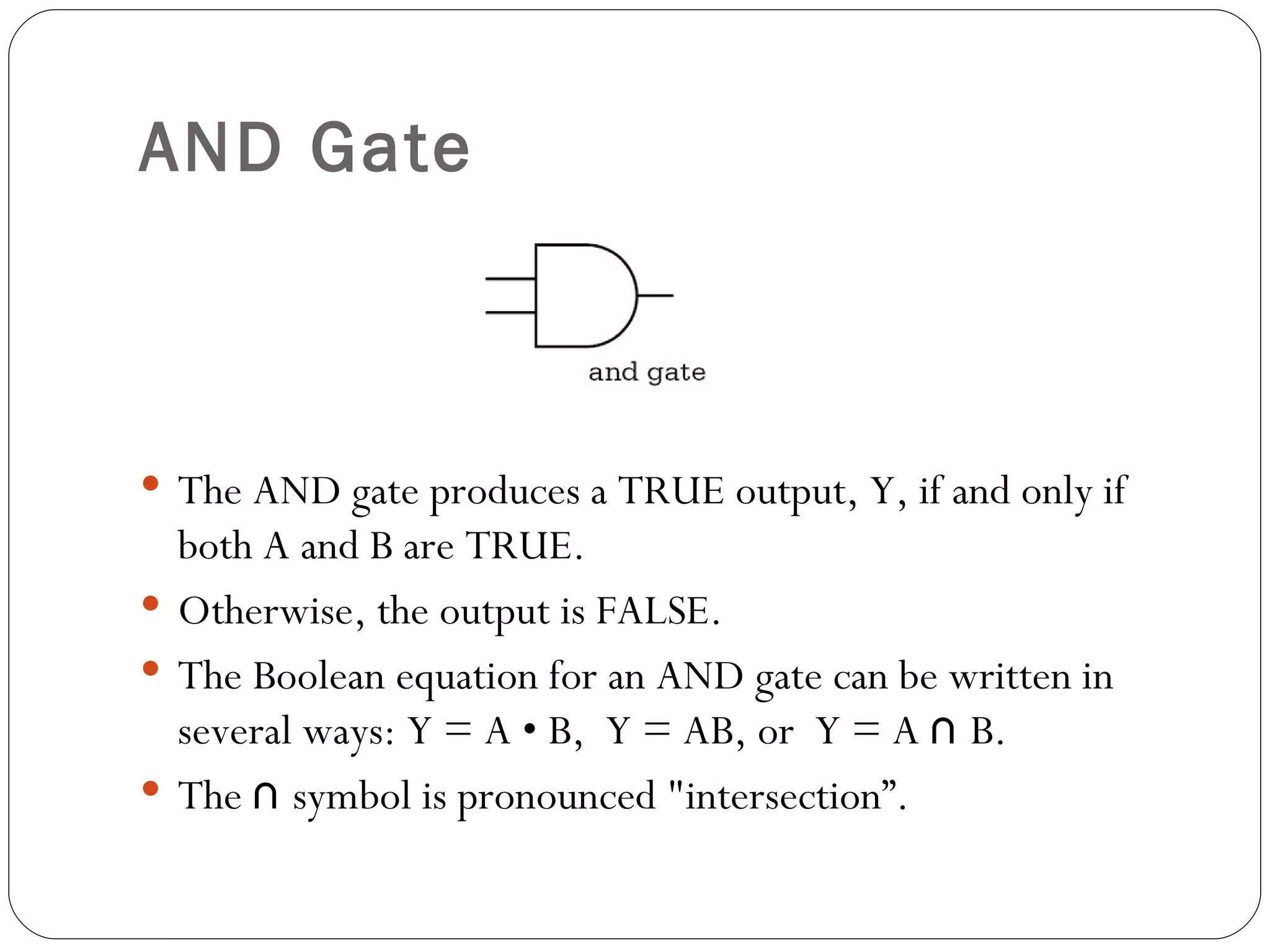
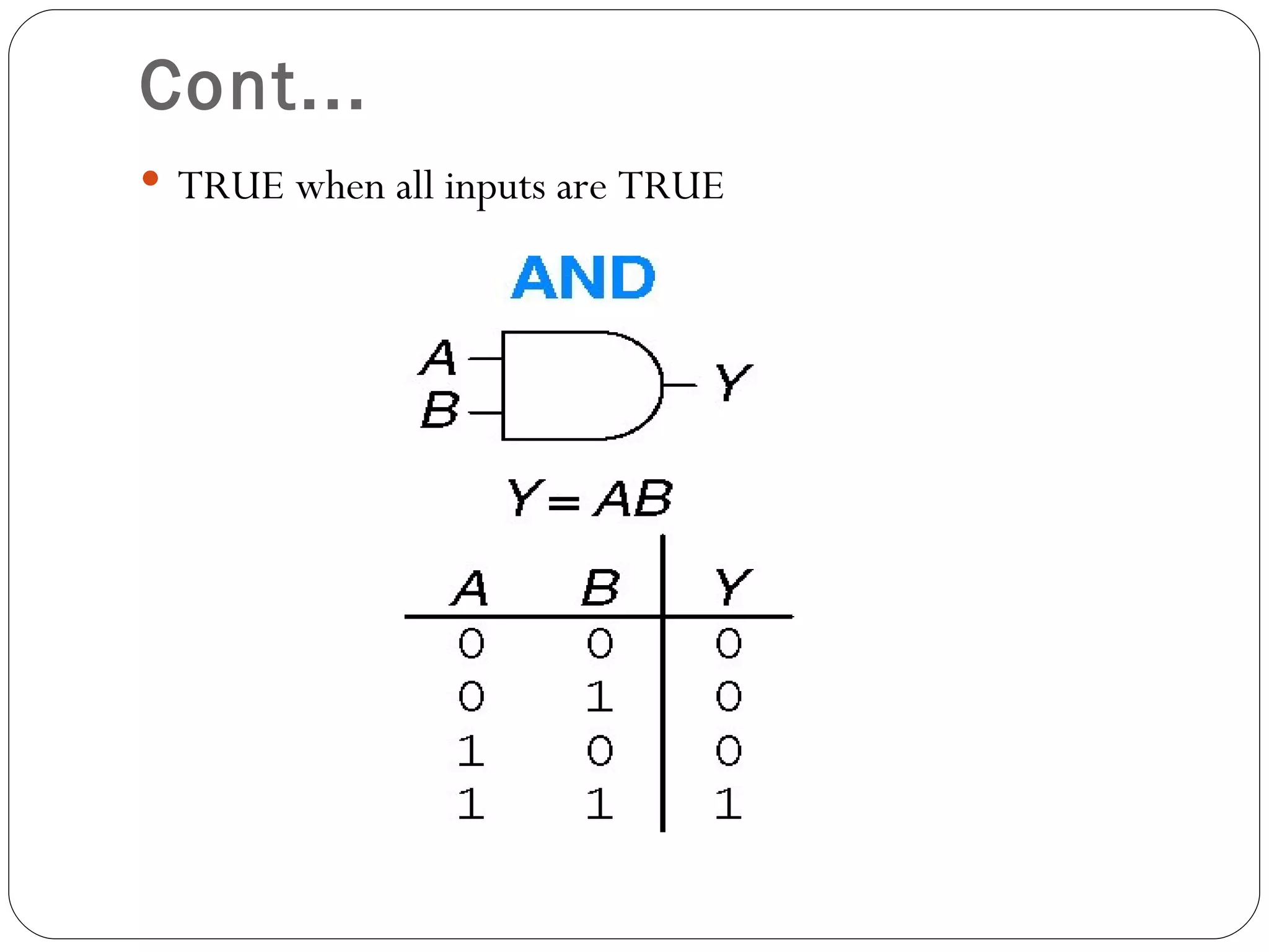
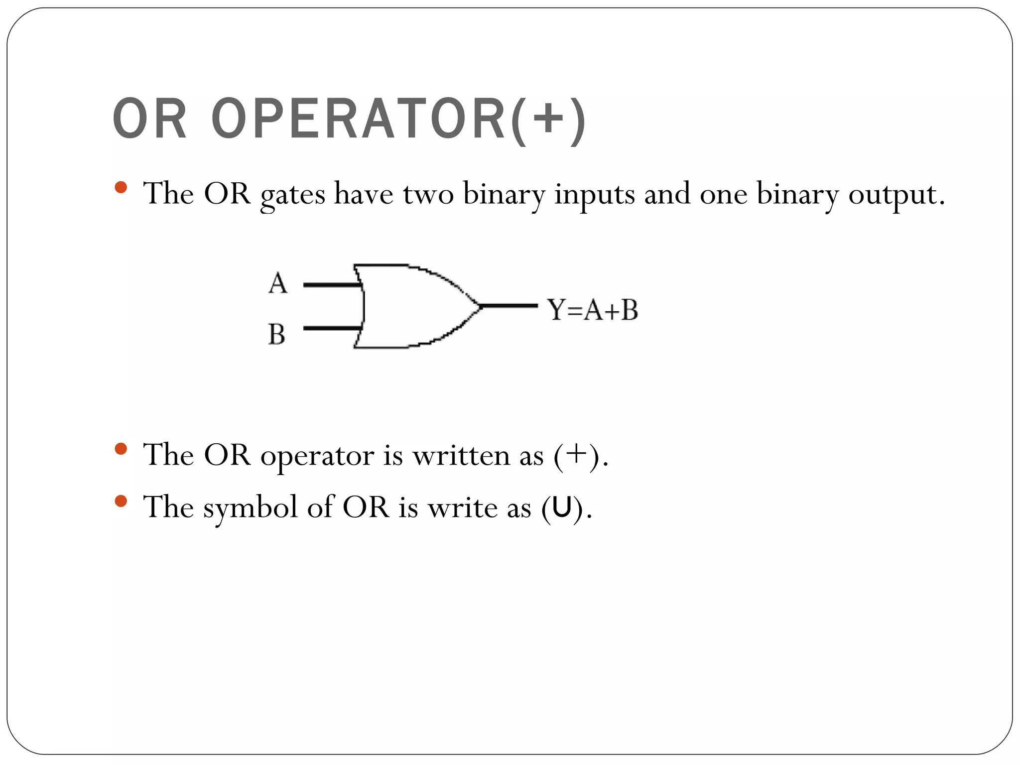
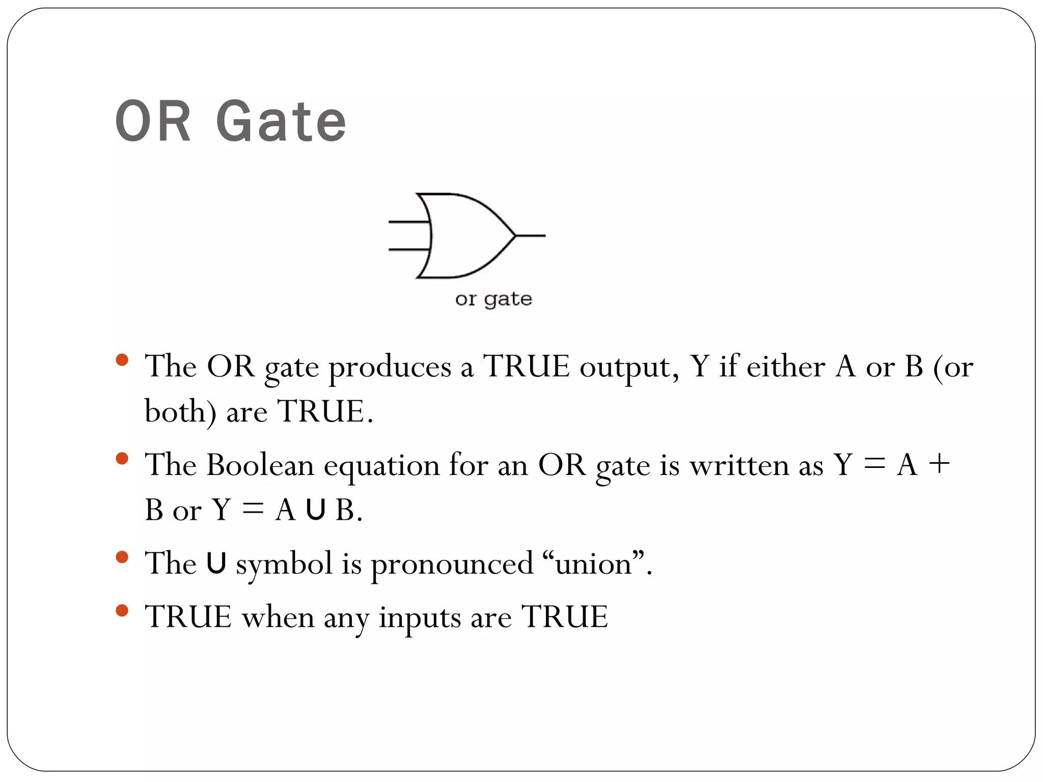
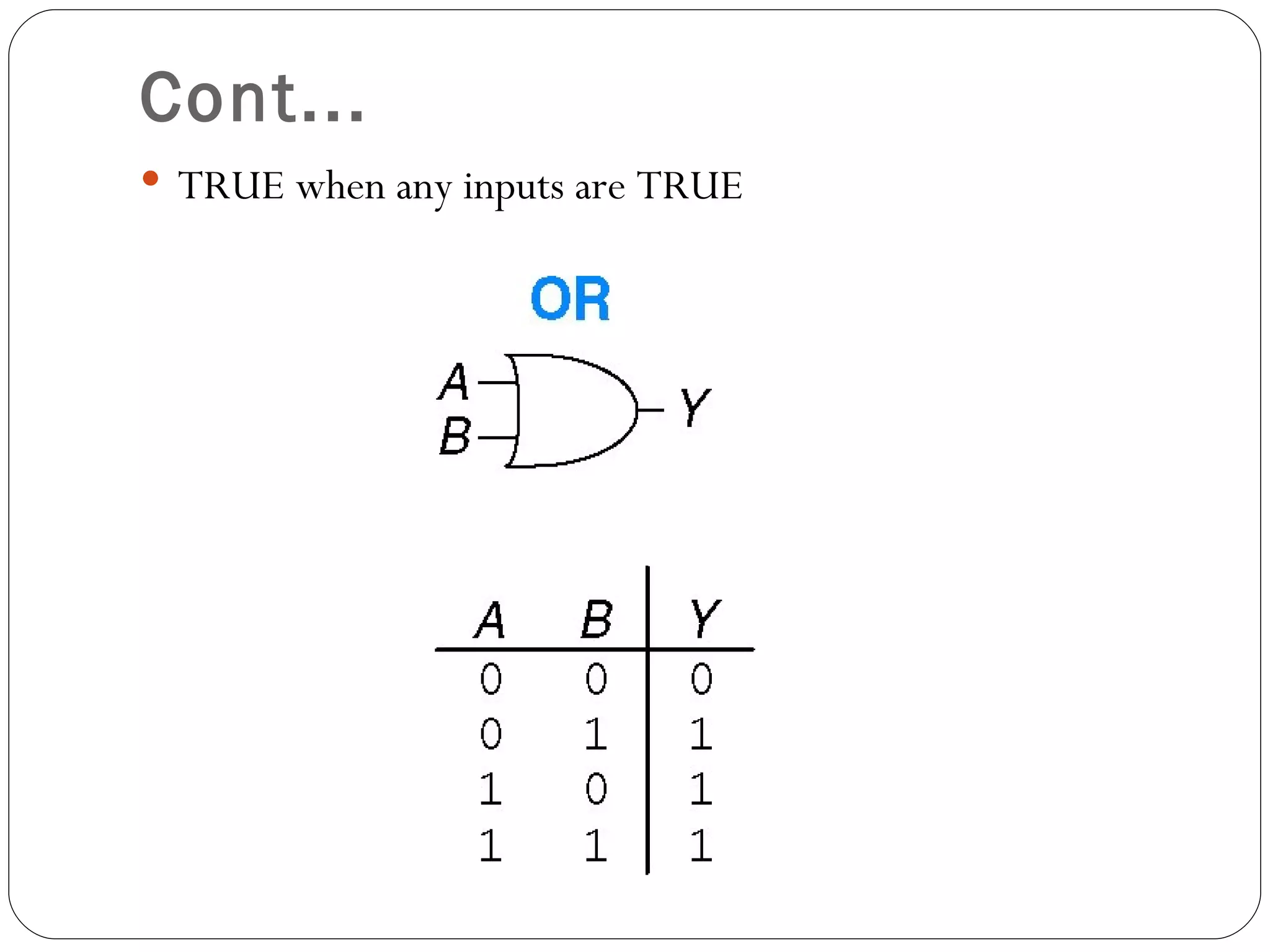
2.4.1 Boolean
  Expression

Learning Outcome:
  • Calculate the value of Boolean
  Expression
Boolean Expression
 Introduction
 Axioms of Boolean Algebra
 Basic Theorems
 Logical Addition (OR Operation)
 Logical Multiplication (AND Operation)
 Complementation
Introduction

 The basic rules for simplifying and combining logic
  gates are called Boolean algebra in honour of
  George Boole (1815-1864).
 There are two types of operator:
  Unary – NOT
  Binary – AND, OR
Axioms of Boolean Algebra
 For any elements a, b and c of the set B on which two binary
  operations (+ , .) and a unary operation denoted (-) or (~) or (ù)
  are defined (OR, AND, NOT respectively), and 0 and 1 denote
  two distinct elements of B. Then
   Commutative Laws
    a+b=b+a
    a.b=b.a
   Distributive Laws
     a + (b . c) = (a + b) . (a + c)
     a . (b + c) = (a . b) + (a . c)
   Identity Laws
    a+0=a
    a.1=a
   Complement Laws
    a+~a=1
    a.~a=0
Basic Theorems
 Let a, b, c be any three elements in a Boolean algebra B. Then
 Idempotent Laws
     a+a=a
     a.a=a
   Boundedness Laws
     a+1=1
     a.0=0
   Absorption Laws
     a + (a . b) = a
     a . (a + b) = a
   Associative Laws
     (a + b ) + c = a + (b + c)
     (a . b) . c = a . (b . c)
   (Uniqueness of Complement)
     If a + x = 1 and a . x = 0, then x = ~ a
 ~0=1~1=0
 De Morgan’s Laws:
Logical Addition (OR
Operation)
 Each variable in Boolean algebra has either of two values:
  true or false (l or 0).
 For instance, in logic equation, A + B = C, each of the
  variables A, B and C may have only the values 0 or 1.
 We can define the “+” symbol by listing all possible
  combinations for A and B and the resulting values of A + B.
Cont...
          Input             Output

    A                 B     C = A+B
    0                 0        0
    1                 0        1
    0                 1        1
    1                 1        1

                  Table 2
Cont...
 Above table is a truth table of logical addition and could
  represent binary addition table except for the last entry.
 The + symbol, therefore, does not have the normal meaning
  of arithmetic addition but is a logical addition and is referred
  as OR operation.
 The equation A + B = C can be read as A OR B equals C.
  This concept can be extended to any number of variables.
 To avoid ambiguity, a number of other symbols have been
  recommended as replacements for the + sign, for example,
  U and therefore A + B = C can be written as A ∪ B = C.
Logical Multiplication (AND
Operation)
  A second important operation in Boolean algebra is logical
   multiplication and is referred to as AND operation.
  The logical multiplication of two variables A and B is expressed as
   A.B and is read as A AND B. The Boolean equation for an AND
   gate can be written in as Y = A • B, Y = AB, or Y = A ∩ B.
  The truth table for logical multiplication of two variables is,

                   Input                         Output
            A                B                  C=A*B
            0                0                      0
            1                0                      0
            0                1                      0
            1                1                      1

                             Table 3
Complementation
 Boolean algebra uses an operation called complementation
  and this can be defined as ~0 = 1 and ~1 = 0.
 ~A means the complement of A and read as NOT A. The
  process of complementing is called negation,

                 Input                Output

                  A                   B=~A

                   0                    1

                   1                    0

                         Table 4
Exercise 1
Evaluate the following Boolean expressions:
l    1+1+1
l    1+1+0
l    1.1.1
l    1.1.0


Answer.
i) 1 + 1 + 1 = (1 + 1) + 1 = 1 + 1 = 1
j) 1 + 1 + 0 = (1 + 1) + 0 = 1 + 0 = 1
k) 1.1.1 = (1.1). 1 = 1.1 = 1
l) 1.1.0 = (1.1). 0 = 1.0 = 0
Exercise 2
Evaluate the following.
l 1. (1 + 0)
l (1 + 1). (1 + 0)
l (1.1) + (0.1)


Answer.
 As in ordinary arithmetic, Operations in parenthesis are done
   first.
i) 1. (1 + 0) = 1.1 = 1
j) (1+1). (1+0) = 1.1 = 1
k) (1.1) + (0.1) = 1 + 0 = 1
Exercise 3
Evaluate 1.1 + 0.1

Answer.
 In ordinary arithmetic, multiplication takes precedence over
  addition. The Boolean AND takes precedence over the
  Boolean OR.
   1.1 + 0.1 = 1 + 0 = 1


 This example illustrates that (1.1) + (0.1) is the same as 1.1
  + 0.1. The brackets are not needed. This is similar to (5 * 2)
  + (3 * 4) = 5 * 2 + 3 * 4. The brackets are not needed.
Exercise 4
  In ordinary mathematics we say that multiplication distributes over
  addition. For (4) 2(a + b) = 2a + 2b
  Does the AND operation distribute over the OR operation? For
  example, is 1. (1 + 0) = 1.1 + 1.0?

Answer.
 Left Side: 1. (1 + 0) = 1.1 = 1
 Right Side: 1.1 + 1.0 = 1 + 0 = 1
 Left side = Right side
 Hence, AND does distribute over OR
 It should be noted that distributive Law of AND over OR does
  hold in general in Boolean arithmetic.
2.4.2     Logic Gates

Learning Outcome:
  Identify symbol for logic gate
2.4.2      Logic Gates
 An electronic circuit operates on one or more
  input signals to produce an output signal.
 Gates are digital (two-state) circuits and can be
  analyzed with Boolean algebra.
 The circuit which performs OR operation is called
  OR gate
 The circuit which performs AND operation is
  called AND gate.
ELECTRICAL
SWITCHES
  Electrical switches are good examples to illustrate OR, AND
   and many Boolean theorems.
Cont....
 A switch has only two states: either closed or open. When the
  two switches are connected in parallel, the current will flow in
  the circuit when either switch is in closed position.
 The current will not flow at all when both switches are in open
  position.
 If the flowing current is taken as ON and not flowing as OFF,
  and assumed that closed = 1, open = 0, ON = 1 and OFF = 0,
  then behaviour of two switches can be tabulated as shown
  below.
 This is precisely the property described by the truth table for
  logical addition (OR operation).
Behaviour of two switches in
parallel
       Switch A              Switch B               Bulb C
  Open            (0)   Open            (0)   OFF            (0)

  Closed          (1)   Open            (0)   ON             (1)

  Open            (0)   Closed          (1)   ON             (1)

  Closed          (1)   Closed          (1)   ON             (1)

                           Table 5
Cont....
 When two switches connected in series as shown below, the
  lamp will light up when both A and B are closed. Table 6
  shows the behaviour of two switches in series circuit.
Behaviour of Two Switches in
Series
        Switch A              Switch B               Bulb C
 Open              (0)   Open            (0)   OFF            (0)

 Closed            (1)   Open            (0)   OFF            (0)

 Open              (0)   Closed          (1)   OFF            (0)

 Closed            (1)   Closed          (1)   ON             (1)

                          Table 6
Logic Gates
 These gates are AND gate, OR gate and NOT
 gate.
Cont...
 A gate will have one or more binary
 inputs of 0 or 1 but just one binary
 output.
 a) The AND and OR gates each have two binary
    inputs and one binary output.
 b) The NOT gate has one binary input and one
    binary output.
Truth Table
 A truth table is a good way to show the function
  of a logic gate.
 It shows the output states for every possible
  combination of input states.
 The symbols 0 (false) and 1 (true) are used in
  truth tables
 For a logic gate with n inputs, there are 2n entries
  in the truth table.
 Example: A logic gate with three inputs, A, B and
  C will contain 23 = 8 entries.
AND Truth Table


   Input A   Input B   Output A.B=Y

      1         1           1

      1         0           0

      0         1           0

      0         0           0
OR Truth Table


   Input A   Input B   Output A+B=Y

      1         1           1

      1         0           1

      0         1           1

      0         0           0
NOT Truth Table


       Input A   Output A’=Y

          0           1

          1           0
THE AND OPERATOR (.)
 The AND gates have two binary inputs and one binary
  output.


 The AND operator is written as (.).
 The symbol of AND is written as (∩).
AND Truth Table
AND Gate


 The AND gate produces a TRUE output, Y, if and only if
  both A and B are TRUE.
 Otherwise, the output is FALSE.
 The Boolean equation for an AND gate can be written in
  several ways: Y = A • B, Y = AB, or Y = A ∩ B.
 The ∩ symbol is pronounced "intersection”.
Cont...
 TRUE when all inputs are TRUE
OR OPERATOR(+)
 The OR gates have two binary inputs and one binary output.


 The OR operator is written as (+).
 The symbol of OR is write as (∪).
OR Truth Table
OR Gate


 The OR gate produces a TRUE output, Y if either A or B (or
  both) are TRUE.
 The Boolean equation for an OR gate is written as Y = A +
  B or Y = A ∪ B.
 The ∪ symbol is pronounced “union”.
 TRUE when any inputs are TRUE
Cont...
 TRUE when any inputs are TRUE
NOT OPERATOR (~)
 The NOT gate has one binary input and one binary
 output.


 The NOT A can be written as below:
  (~A), ( ), (¬A), (A’), (!A ).
NOT Gate
 The NOT gate's output is the inverse of its input. If A is
  FALSE, then Y is TRUE. If A is TRUE, then Y is FALSE.
 This relationship is summarized by the truth table and
  Boolean equation.
 The line over A in the Boolean equation is pronounced
  NOT, so Y is read as “Y equals NOT A”.
 The NOT gate is also called an inverter.
NOT Truth Table
 ~0 = 1 is read as NOT 0 equals to 1. It is important to
  remember that the NOT function inverts input.
 The NOT function takes an input of 0 and inverts it to
  provide an output of 1 and it takes an input of 1 and inverts it
  to provide an output of 0.
Cont...
Review Question
 Explain the following logic gates:

  Operator      Symbol       Gate      Input Gate, n   Input Truth
                                                        Table (2n)
    AND

     OR

    NOT

    NAND

    NOR
 Explain the following logic gates:

  Operator      Symbol           Gate   Input Gate, n   Input Truth
                                                         Table (2n)

    AND         ., ∩                         2              4

     OR         +, ∪                         2              4

             (~), ( ), (¬),
    NOT                                      1              2
                (’), (! ).

    NAND                                     2              4

    NOR                                      2              4

                              Table 7
Exercise
Write a boolean expression and draw the truth table to represent this
logic circuit diagram.


                   A

                   B
                                C
Answer
           A   B    C        Output (Y)
Y= A.B.C
           0   0     0           0

           0   0     1           0

           0   1     0           0

           0   1     1           0

           1   0     0           0
           1   0     1           0

           1   1     0           0

           1   1     1           1

                   Table 8
Exercise
Write a boolean expression and draw the truth table to represent this
logic circuit diagram.
Answer
               A   B    C        Output
Y= (A.B) + C
               0   0     0         0

               0   0     1         1

               0   1     0         0

               0   1     1         1

               1   0     0         0
               1   0     1         1

               1   1     0         1

               1   1     1         1

                       Table 9
Exercise
Write a boolean expression and draw the truth table to represent this
logic circuit diagram.


             A
             B                                Y
                             C
Answer
            A   B    C    Output (Y)
Y= (A+B)C
            0   0    0        0

            0   0    1        0

            0   1    0        0

            0   1    1        1

            1   0    0        0
            1   0    1        1

            1   1    0        0

            1   1    1        1

                    Table 9
2.4.3 Simple Logic
Circuit

Learning Outcome:
  Draw simple logic circuit from a
  given boolean expression
Simple Logic Circuit
 Draw a logic circuit for (A + B)C.
Simple Logic Circuit
 Draw a logic circuit for A + BC + D.
Simple Logic Circuit
 Draw a logic circuit for (A + B)C.

Lecture 2.4 logic_gate_&_simple_logic_circuit

  • 1.
    2.4.1 Boolean Expression Learning Outcome: • Calculate the value of Boolean Expression
  • 2.
    Boolean Expression  Introduction Axioms of Boolean Algebra  Basic Theorems  Logical Addition (OR Operation)  Logical Multiplication (AND Operation)  Complementation
  • 3.
    Introduction  The basicrules for simplifying and combining logic gates are called Boolean algebra in honour of George Boole (1815-1864).  There are two types of operator: Unary – NOT Binary – AND, OR
  • 4.
    Axioms of BooleanAlgebra  For any elements a, b and c of the set B on which two binary operations (+ , .) and a unary operation denoted (-) or (~) or (ù) are defined (OR, AND, NOT respectively), and 0 and 1 denote two distinct elements of B. Then  Commutative Laws a+b=b+a a.b=b.a  Distributive Laws  a + (b . c) = (a + b) . (a + c)  a . (b + c) = (a . b) + (a . c)  Identity Laws a+0=a a.1=a  Complement Laws a+~a=1 a.~a=0
  • 5.
    Basic Theorems  Leta, b, c be any three elements in a Boolean algebra B. Then  Idempotent Laws  a+a=a  a.a=a  Boundedness Laws  a+1=1  a.0=0  Absorption Laws  a + (a . b) = a  a . (a + b) = a  Associative Laws  (a + b ) + c = a + (b + c)  (a . b) . c = a . (b . c)  (Uniqueness of Complement)  If a + x = 1 and a . x = 0, then x = ~ a  ~0=1~1=0  De Morgan’s Laws:
  • 6.
    Logical Addition (OR Operation) Each variable in Boolean algebra has either of two values: true or false (l or 0).  For instance, in logic equation, A + B = C, each of the variables A, B and C may have only the values 0 or 1.  We can define the “+” symbol by listing all possible combinations for A and B and the resulting values of A + B.
  • 7.
    Cont... Input Output A B C = A+B 0 0 0 1 0 1 0 1 1 1 1 1 Table 2
  • 8.
    Cont...  Above tableis a truth table of logical addition and could represent binary addition table except for the last entry.  The + symbol, therefore, does not have the normal meaning of arithmetic addition but is a logical addition and is referred as OR operation.  The equation A + B = C can be read as A OR B equals C. This concept can be extended to any number of variables.  To avoid ambiguity, a number of other symbols have been recommended as replacements for the + sign, for example, U and therefore A + B = C can be written as A ∪ B = C.
  • 9.
    Logical Multiplication (AND Operation)  A second important operation in Boolean algebra is logical multiplication and is referred to as AND operation.  The logical multiplication of two variables A and B is expressed as A.B and is read as A AND B. The Boolean equation for an AND gate can be written in as Y = A • B, Y = AB, or Y = A ∩ B.  The truth table for logical multiplication of two variables is, Input Output A B C=A*B 0 0 0 1 0 0 0 1 0 1 1 1 Table 3
  • 10.
    Complementation  Boolean algebrauses an operation called complementation and this can be defined as ~0 = 1 and ~1 = 0.  ~A means the complement of A and read as NOT A. The process of complementing is called negation, Input Output A B=~A 0 1 1 0 Table 4
  • 11.
    Exercise 1 Evaluate thefollowing Boolean expressions: l 1+1+1 l 1+1+0 l 1.1.1 l 1.1.0 Answer. i) 1 + 1 + 1 = (1 + 1) + 1 = 1 + 1 = 1 j) 1 + 1 + 0 = (1 + 1) + 0 = 1 + 0 = 1 k) 1.1.1 = (1.1). 1 = 1.1 = 1 l) 1.1.0 = (1.1). 0 = 1.0 = 0
  • 12.
    Exercise 2 Evaluate thefollowing. l 1. (1 + 0) l (1 + 1). (1 + 0) l (1.1) + (0.1) Answer.  As in ordinary arithmetic, Operations in parenthesis are done first. i) 1. (1 + 0) = 1.1 = 1 j) (1+1). (1+0) = 1.1 = 1 k) (1.1) + (0.1) = 1 + 0 = 1
  • 13.
    Exercise 3 Evaluate 1.1+ 0.1 Answer.  In ordinary arithmetic, multiplication takes precedence over addition. The Boolean AND takes precedence over the Boolean OR.  1.1 + 0.1 = 1 + 0 = 1  This example illustrates that (1.1) + (0.1) is the same as 1.1 + 0.1. The brackets are not needed. This is similar to (5 * 2) + (3 * 4) = 5 * 2 + 3 * 4. The brackets are not needed.
  • 14.
    Exercise 4 In ordinary mathematics we say that multiplication distributes over addition. For (4) 2(a + b) = 2a + 2b Does the AND operation distribute over the OR operation? For example, is 1. (1 + 0) = 1.1 + 1.0? Answer.  Left Side: 1. (1 + 0) = 1.1 = 1  Right Side: 1.1 + 1.0 = 1 + 0 = 1  Left side = Right side  Hence, AND does distribute over OR  It should be noted that distributive Law of AND over OR does hold in general in Boolean arithmetic.
  • 15.
    2.4.2 Logic Gates Learning Outcome:  Identify symbol for logic gate
  • 16.
    2.4.2 Logic Gates  An electronic circuit operates on one or more input signals to produce an output signal.  Gates are digital (two-state) circuits and can be analyzed with Boolean algebra.  The circuit which performs OR operation is called OR gate  The circuit which performs AND operation is called AND gate.
  • 17.
    ELECTRICAL SWITCHES  Electricalswitches are good examples to illustrate OR, AND and many Boolean theorems.
  • 18.
    Cont....  A switchhas only two states: either closed or open. When the two switches are connected in parallel, the current will flow in the circuit when either switch is in closed position.  The current will not flow at all when both switches are in open position.  If the flowing current is taken as ON and not flowing as OFF, and assumed that closed = 1, open = 0, ON = 1 and OFF = 0, then behaviour of two switches can be tabulated as shown below.  This is precisely the property described by the truth table for logical addition (OR operation).
  • 19.
    Behaviour of twoswitches in parallel Switch A Switch B Bulb C Open (0) Open (0) OFF (0) Closed (1) Open (0) ON (1) Open (0) Closed (1) ON (1) Closed (1) Closed (1) ON (1) Table 5
  • 20.
    Cont....  When twoswitches connected in series as shown below, the lamp will light up when both A and B are closed. Table 6 shows the behaviour of two switches in series circuit.
  • 21.
    Behaviour of TwoSwitches in Series Switch A Switch B Bulb C Open (0) Open (0) OFF (0) Closed (1) Open (0) OFF (0) Open (0) Closed (1) OFF (0) Closed (1) Closed (1) ON (1) Table 6
  • 22.
    Logic Gates  Thesegates are AND gate, OR gate and NOT gate.
  • 23.
    Cont...  A gatewill have one or more binary inputs of 0 or 1 but just one binary output. a) The AND and OR gates each have two binary inputs and one binary output. b) The NOT gate has one binary input and one binary output.
  • 24.
    Truth Table  Atruth table is a good way to show the function of a logic gate.  It shows the output states for every possible combination of input states.  The symbols 0 (false) and 1 (true) are used in truth tables  For a logic gate with n inputs, there are 2n entries in the truth table.  Example: A logic gate with three inputs, A, B and C will contain 23 = 8 entries.
  • 25.
    AND Truth Table Input A Input B Output A.B=Y 1 1 1 1 0 0 0 1 0 0 0 0
  • 26.
    OR Truth Table Input A Input B Output A+B=Y 1 1 1 1 0 1 0 1 1 0 0 0
  • 27.
    NOT Truth Table Input A Output A’=Y 0 1 1 0
  • 28.
    THE AND OPERATOR(.)  The AND gates have two binary inputs and one binary output.  The AND operator is written as (.).  The symbol of AND is written as (∩).
  • 29.
  • 30.
    AND Gate  TheAND gate produces a TRUE output, Y, if and only if both A and B are TRUE.  Otherwise, the output is FALSE.  The Boolean equation for an AND gate can be written in several ways: Y = A • B, Y = AB, or Y = A ∩ B.  The ∩ symbol is pronounced "intersection”.
  • 31.
    Cont...  TRUE whenall inputs are TRUE
  • 32.
    OR OPERATOR(+)  TheOR gates have two binary inputs and one binary output.  The OR operator is written as (+).  The symbol of OR is write as (∪).
  • 33.
  • 34.
    OR Gate  TheOR gate produces a TRUE output, Y if either A or B (or both) are TRUE.  The Boolean equation for an OR gate is written as Y = A + B or Y = A ∪ B.  The ∪ symbol is pronounced “union”.  TRUE when any inputs are TRUE
  • 35.
    Cont...  TRUE whenany inputs are TRUE
  • 36.
    NOT OPERATOR (~) The NOT gate has one binary input and one binary output.  The NOT A can be written as below: (~A), ( ), (¬A), (A’), (!A ).
  • 37.
    NOT Gate  TheNOT gate's output is the inverse of its input. If A is FALSE, then Y is TRUE. If A is TRUE, then Y is FALSE.  This relationship is summarized by the truth table and Boolean equation.  The line over A in the Boolean equation is pronounced NOT, so Y is read as “Y equals NOT A”.  The NOT gate is also called an inverter.
  • 38.
    NOT Truth Table ~0 = 1 is read as NOT 0 equals to 1. It is important to remember that the NOT function inverts input.  The NOT function takes an input of 0 and inverts it to provide an output of 1 and it takes an input of 1 and inverts it to provide an output of 0.
  • 39.
  • 40.
    Review Question  Explainthe following logic gates: Operator Symbol Gate Input Gate, n Input Truth Table (2n) AND OR NOT NAND NOR
  • 41.
     Explain thefollowing logic gates: Operator Symbol Gate Input Gate, n Input Truth Table (2n) AND ., ∩ 2 4 OR +, ∪ 2 4 (~), ( ), (¬), NOT 1 2 (’), (! ). NAND 2 4 NOR 2 4 Table 7
  • 42.
    Exercise Write a booleanexpression and draw the truth table to represent this logic circuit diagram. A B C
  • 43.
    Answer A B C Output (Y) Y= A.B.C 0 0 0 0 0 0 1 0 0 1 0 0 0 1 1 0 1 0 0 0 1 0 1 0 1 1 0 0 1 1 1 1 Table 8
  • 44.
    Exercise Write a booleanexpression and draw the truth table to represent this logic circuit diagram.
  • 45.
    Answer A B C Output Y= (A.B) + C 0 0 0 0 0 0 1 1 0 1 0 0 0 1 1 1 1 0 0 0 1 0 1 1 1 1 0 1 1 1 1 1 Table 9
  • 46.
    Exercise Write a booleanexpression and draw the truth table to represent this logic circuit diagram. A B Y C
  • 47.
    Answer A B C Output (Y) Y= (A+B)C 0 0 0 0 0 0 1 0 0 1 0 0 0 1 1 1 1 0 0 0 1 0 1 1 1 1 0 0 1 1 1 1 Table 9
  • 48.
    2.4.3 Simple Logic Circuit LearningOutcome:  Draw simple logic circuit from a given boolean expression
  • 49.
    Simple Logic Circuit Draw a logic circuit for (A + B)C.
  • 50.
    Simple Logic Circuit Draw a logic circuit for A + BC + D.
  • 51.
    Simple Logic Circuit Draw a logic circuit for (A + B)C.