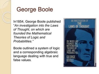
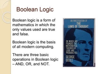
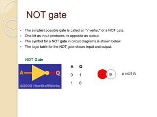
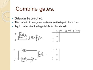
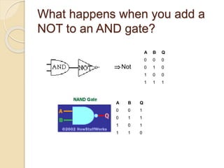
Boolean Logic
George Boole
In1854, George Boole published
“An investigation into the Laws
of Thought, on which are
founded the Mathematical
Theories of Logic and
Probabilities.”
Boole outlined a system of logic
and a corresponding algebraic
language dealing with true and
false values.
Boolean Logic
Boolean logic is a form of
mathematics in which the
only values used are true
and false.
Boolean logic is the basis
of all modern computing.
There are three basic
operations in Boolean logic
– AND, OR, and NOT.
The AND Operation
AND
b
T F
a
T T F
F F F
The AND operation is a binary
operation, meaning that it needs
two operands.
c = a AND b
Both a and b must be true for the
result to be true.
The OR Operation
The OR operation is also a
binary operation with two
operands.
c = a OR b
If either a OR b is true, then
the result is true.
OR
b
T F
a
T T T
F T F
The NOT Operation
The NOT operation is a unary
operation with only one operand.
c = NOT (a)
It simply reverses the true or
false value of the operand.
NOT
a
T F
F T
Let’s use Boolean logic to
examine class.
 Please stand up if you are:
◦ girl
◦ AND black hair
◦ AND left handed
 Please stand up if you are:
◦ girl
◦ OR black hair
◦ OR left handed
 And NOT
 How has the group changed depending on the logical
operator used.
Logical Conditions
Logical comparisons that are
either true or false are most
often used as the basis for
the true and false values in
Boolean logic.
They are often used for simple
conditions in branching and
looping instructions.
If (hours > 40)
pay overtime
If (age < 12)
stay in the back seat
While (count  10)
print count
increment count
Nesting
 When more than one element is in parentheses, the sequence is
left to right. This is called "nesting.“
◦ (foxes OR rabbits) AND pest control
◦ foxes OR rabbits AND pest control
◦ (animal pests OR pest animals) NOT rabbits
Order of precedence of Boolean
operators
 The order of operations is: AND, NOT, OR, XOR
 Parentheses are used to override priority.
 Expressions in parentheses are processed first.
 Parentheses are used to organize the sequence and
groups of concepts.
Write out logic statements using
Boolean operators for these.
• You have a buzzer in your car that sounds when your
keys are in the ignition and the door is open.
• You have a fire alarm installed in your house. This
alarm will sound if it senses heat or smoke.
• There is an election coming up. People are allowed to
vote if they are a citizen and they are 18.
• To complete an assignment the students must do a
presentation or write an essay.
Basis for digital computers.
 The true-false nature of Boolean
logic makes it compatible with
binary logic used in digital
computers.
 Electronic circuits can produce
Boolean logic operations.
 Circuits are called gates.
◦ NOT
◦ AND
◦ OR
AND gate
 The AND gate has the following symbol and
logic table.
 Two or more input bits produce one output bit.
 Both inputs must be true (1) for the output to be
true.
 Otherwise the output is false (0).
A B Q
0 0 0
0 1 0
1 0 0
1 1 1
OR gate
 The OR gate has the following symbol and logic table.
 Two or more input bits produce one output bit.
 Either inputs must be true (1) for the output to be true.
A B Q
0 0 0
0 1 1
1 0 1
1 1 1
NOT gate
 The simplest possible gate is called an "inverter," or a NOT gate.
 One bit as input produces its opposite as output.
 The symbol for a NOT gate in circuit diagrams is shown below.
 The logic table for the NOT gate shows input and output.
A Q
0 1
1 0
Combine gates.
 Gates can be combined.
 The output of one gate can become the input of another.
 Try to determine the logic table for this circuit.
What happens when you add a
NOT to an AND gate?
Not
A B Q
0 0 0
0 1 0
1 0 0
1 1 1
A B Q
0 0 1
0 1 1
1 0 1
1 1 0
Can you make an AND gate from
an NAND?
A B Q
0 0 0
0 1 0
1 0 0
1 1 1
“Exclusive” gates
 Exclusively OR gate are true if either input is true but
not both.
A B Q
0 0 0
0 1 1
1 0 1
1 1 0
A B Q
0 0 1
0 1 0
1 0 0
1 1 1
Truth Tables
xy = x AND y = x * y x + y = x OR y x bar = NOT x
AND is true only if OR is true if either NOT inverts the bit
both inputs are true inputs are true We will denote x bar as ~X
NOR is NOT of OR NAND is NOT of AND XOR is true if both inputs
differ
Logic Gates
Here we see the logic gates
that represent the boolean
operations previously
discussed
XOR looks like OR
but with the added
curved line
We typically represent NOR and NAND by the two
on the left, but the two on the right are also correct
How do we use gates to add two
binary numbers?
 Binary numbers are either 1 or 0, either on or off.
 Have two outputs.
 Need a gate to produce each output.
0 0 1 1
+ 0 + 1 + 0 + 1
00 01 01 10
A B Q CO
0 0 0 0
0 1 1 0
1 0 1 0
1 1 0 1
An Example: Half Adder
• There are 4 possibilities
when adding 2 bits
together:
0 + 0 0 + 1 1 + 0 1 + 1
• In the first case, we have a sum
of 0 and a carry of 0
• In the second and third cases,
we have a sum of 1 and a carry
of 0
• In the last case, we have a sum
of 0 and a carry of 1
• These patterns are
demonstrated in the truth table
above to the right
• Notice that sum computes
the same as XOR and carry
computes the same as AND
• We build an Adder using just
one XOR and one AND gate
The truth table for Sum and Carry
and a circuit to compute these
Full Adder
 The half adder really only does half the work
◦ adds 2 bits, but only 2 bits
 If we want to add 2 n-bit
numbers, we need to also
include the carry in from the
previous half adder
◦ So, our circuit becomes more
complicated
 In adding 3 bits (one bit from
x, one bit from y, and the
carry in from the previous
addition), we have 8
possibilities
◦ The sum will either be 0 or 1 and the
carry out will either be 0 or 1
◦ The truth table is given to the right
Building a Full Adder Circuit
 The sum is 1 only if one of x, y
and carry in are 1, or if all three
are 1, the sum is 0 otherwise
 The carry out is 1 if two or three
of x, y and carry in were 1, 0
otherwise
◦ The circuit to the right captures this
by using 2 XOR gates for Sum and 2
AND gates and an OR gate for Carry
Out

Boolean+logic

  • 1.
  • 2.
    George Boole In1854, GeorgeBoole published “An investigation into the Laws of Thought, on which are founded the Mathematical Theories of Logic and Probabilities.” Boole outlined a system of logic and a corresponding algebraic language dealing with true and false values.
  • 3.
    Boolean Logic Boolean logicis a form of mathematics in which the only values used are true and false. Boolean logic is the basis of all modern computing. There are three basic operations in Boolean logic – AND, OR, and NOT.
  • 4.
    The AND Operation AND b TF a T T F F F F The AND operation is a binary operation, meaning that it needs two operands. c = a AND b Both a and b must be true for the result to be true.
  • 5.
    The OR Operation TheOR operation is also a binary operation with two operands. c = a OR b If either a OR b is true, then the result is true. OR b T F a T T T F T F
  • 6.
    The NOT Operation TheNOT operation is a unary operation with only one operand. c = NOT (a) It simply reverses the true or false value of the operand. NOT a T F F T
  • 7.
    Let’s use Booleanlogic to examine class.  Please stand up if you are: ◦ girl ◦ AND black hair ◦ AND left handed  Please stand up if you are: ◦ girl ◦ OR black hair ◦ OR left handed  And NOT  How has the group changed depending on the logical operator used.
  • 8.
    Logical Conditions Logical comparisonsthat are either true or false are most often used as the basis for the true and false values in Boolean logic. They are often used for simple conditions in branching and looping instructions. If (hours > 40) pay overtime If (age < 12) stay in the back seat While (count  10) print count increment count
  • 9.
    Nesting  When morethan one element is in parentheses, the sequence is left to right. This is called "nesting.“ ◦ (foxes OR rabbits) AND pest control ◦ foxes OR rabbits AND pest control ◦ (animal pests OR pest animals) NOT rabbits
  • 10.
    Order of precedenceof Boolean operators  The order of operations is: AND, NOT, OR, XOR  Parentheses are used to override priority.  Expressions in parentheses are processed first.  Parentheses are used to organize the sequence and groups of concepts.
  • 11.
    Write out logicstatements using Boolean operators for these. • You have a buzzer in your car that sounds when your keys are in the ignition and the door is open. • You have a fire alarm installed in your house. This alarm will sound if it senses heat or smoke. • There is an election coming up. People are allowed to vote if they are a citizen and they are 18. • To complete an assignment the students must do a presentation or write an essay.
  • 12.
    Basis for digitalcomputers.  The true-false nature of Boolean logic makes it compatible with binary logic used in digital computers.  Electronic circuits can produce Boolean logic operations.  Circuits are called gates. ◦ NOT ◦ AND ◦ OR
  • 13.
    AND gate  TheAND gate has the following symbol and logic table.  Two or more input bits produce one output bit.  Both inputs must be true (1) for the output to be true.  Otherwise the output is false (0). A B Q 0 0 0 0 1 0 1 0 0 1 1 1
  • 14.
    OR gate  TheOR gate has the following symbol and logic table.  Two or more input bits produce one output bit.  Either inputs must be true (1) for the output to be true. A B Q 0 0 0 0 1 1 1 0 1 1 1 1
  • 15.
    NOT gate  Thesimplest possible gate is called an "inverter," or a NOT gate.  One bit as input produces its opposite as output.  The symbol for a NOT gate in circuit diagrams is shown below.  The logic table for the NOT gate shows input and output. A Q 0 1 1 0
  • 16.
    Combine gates.  Gatescan be combined.  The output of one gate can become the input of another.  Try to determine the logic table for this circuit.
  • 17.
    What happens whenyou add a NOT to an AND gate? Not A B Q 0 0 0 0 1 0 1 0 0 1 1 1 A B Q 0 0 1 0 1 1 1 0 1 1 1 0
  • 18.
    Can you makean AND gate from an NAND? A B Q 0 0 0 0 1 0 1 0 0 1 1 1
  • 19.
    “Exclusive” gates  ExclusivelyOR gate are true if either input is true but not both. A B Q 0 0 0 0 1 1 1 0 1 1 1 0 A B Q 0 0 1 0 1 0 1 0 0 1 1 1
  • 20.
    Truth Tables xy =x AND y = x * y x + y = x OR y x bar = NOT x AND is true only if OR is true if either NOT inverts the bit both inputs are true inputs are true We will denote x bar as ~X NOR is NOT of OR NAND is NOT of AND XOR is true if both inputs differ
  • 21.
    Logic Gates Here wesee the logic gates that represent the boolean operations previously discussed XOR looks like OR but with the added curved line We typically represent NOR and NAND by the two on the left, but the two on the right are also correct
  • 22.
    How do weuse gates to add two binary numbers?  Binary numbers are either 1 or 0, either on or off.  Have two outputs.  Need a gate to produce each output. 0 0 1 1 + 0 + 1 + 0 + 1 00 01 01 10 A B Q CO 0 0 0 0 0 1 1 0 1 0 1 0 1 1 0 1
  • 23.
    An Example: HalfAdder • There are 4 possibilities when adding 2 bits together: 0 + 0 0 + 1 1 + 0 1 + 1 • In the first case, we have a sum of 0 and a carry of 0 • In the second and third cases, we have a sum of 1 and a carry of 0 • In the last case, we have a sum of 0 and a carry of 1 • These patterns are demonstrated in the truth table above to the right • Notice that sum computes the same as XOR and carry computes the same as AND • We build an Adder using just one XOR and one AND gate The truth table for Sum and Carry and a circuit to compute these
  • 24.
    Full Adder  Thehalf adder really only does half the work ◦ adds 2 bits, but only 2 bits  If we want to add 2 n-bit numbers, we need to also include the carry in from the previous half adder ◦ So, our circuit becomes more complicated  In adding 3 bits (one bit from x, one bit from y, and the carry in from the previous addition), we have 8 possibilities ◦ The sum will either be 0 or 1 and the carry out will either be 0 or 1 ◦ The truth table is given to the right
  • 25.
    Building a FullAdder Circuit  The sum is 1 only if one of x, y and carry in are 1, or if all three are 1, the sum is 0 otherwise  The carry out is 1 if two or three of x, y and carry in were 1, 0 otherwise ◦ The circuit to the right captures this by using 2 XOR gates for Sum and 2 AND gates and an OR gate for Carry Out