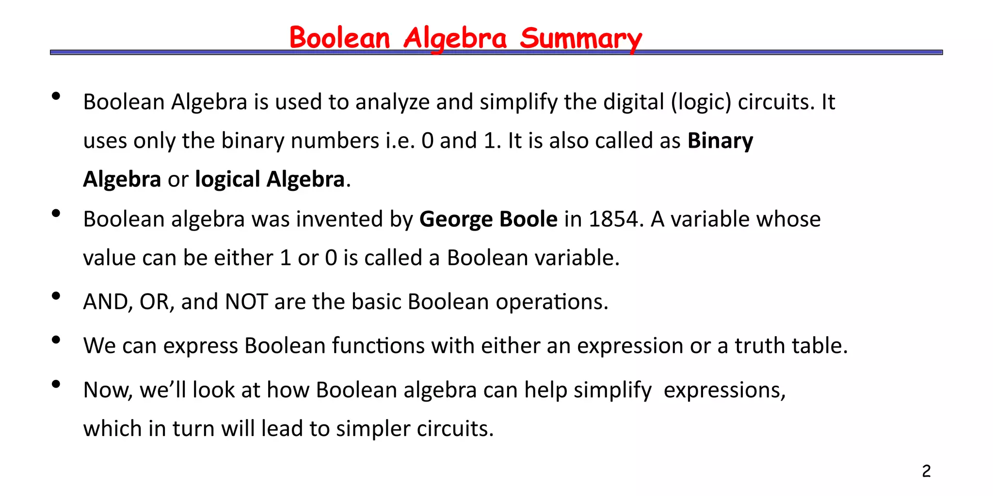
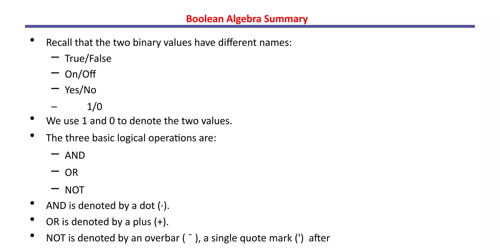
- Boolean algebra uses binary numbers (0 and 1) and logical operations (AND, OR, NOT) to analyze and simplify digital circuits.
- It was invented by George Boole in 1854 and represents variables that can be either 1 or 0.
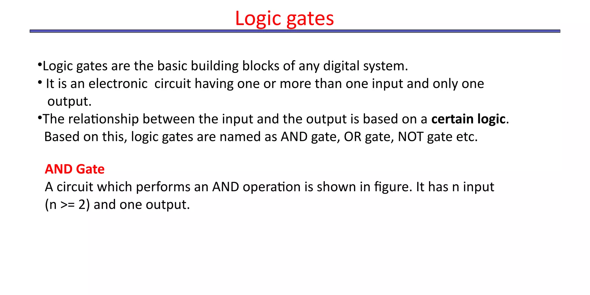
- The document discusses Boolean operations, laws, logic gates, minimization techniques, and representing functions as sums of products.
![Problem
Minimize the following Boolean expression using Boolean identities −
F(A,B,C)=A′B+BC′+BC+AB′C′
Given F(A,B,C)=A′B+BC′+BC+AB′C′
F(A,B,C)=A′B+B(C′+C)+AB′C′
F(A,B,C)=A’B+B.1+AB’C’
= A’B+B+AB’C’ [B.1=B]
= B(A’+1)+AB’C’ [A’+1=1]
= B+AB’C’ [Apply distributive law A+BC=(A+B)(A+C)]
= (B+B’)(B+AC’) [B+B’=1]
= B+AC’](https://image.slidesharecdn.com/boolean-algebra-230110163159-1813a68f/75/boolean-algebra-pdf-36-2048.jpg)
![Problem
Minimize the following Boolean expression using Boolean identities −
F(A,B,C)=(A+B)(A+C)
Given, F(A,B,C)=(A+B)(A+C)
F(A,B,C)=A.A+A.C+B.A+B.C
=A+AC+AB+BC [A.A=A]
= A(1+C+B)+BC [1+Anything=1]
= A+BC](https://image.slidesharecdn.com/boolean-algebra-230110163159-1813a68f/75/boolean-algebra-pdf-37-2048.jpg)