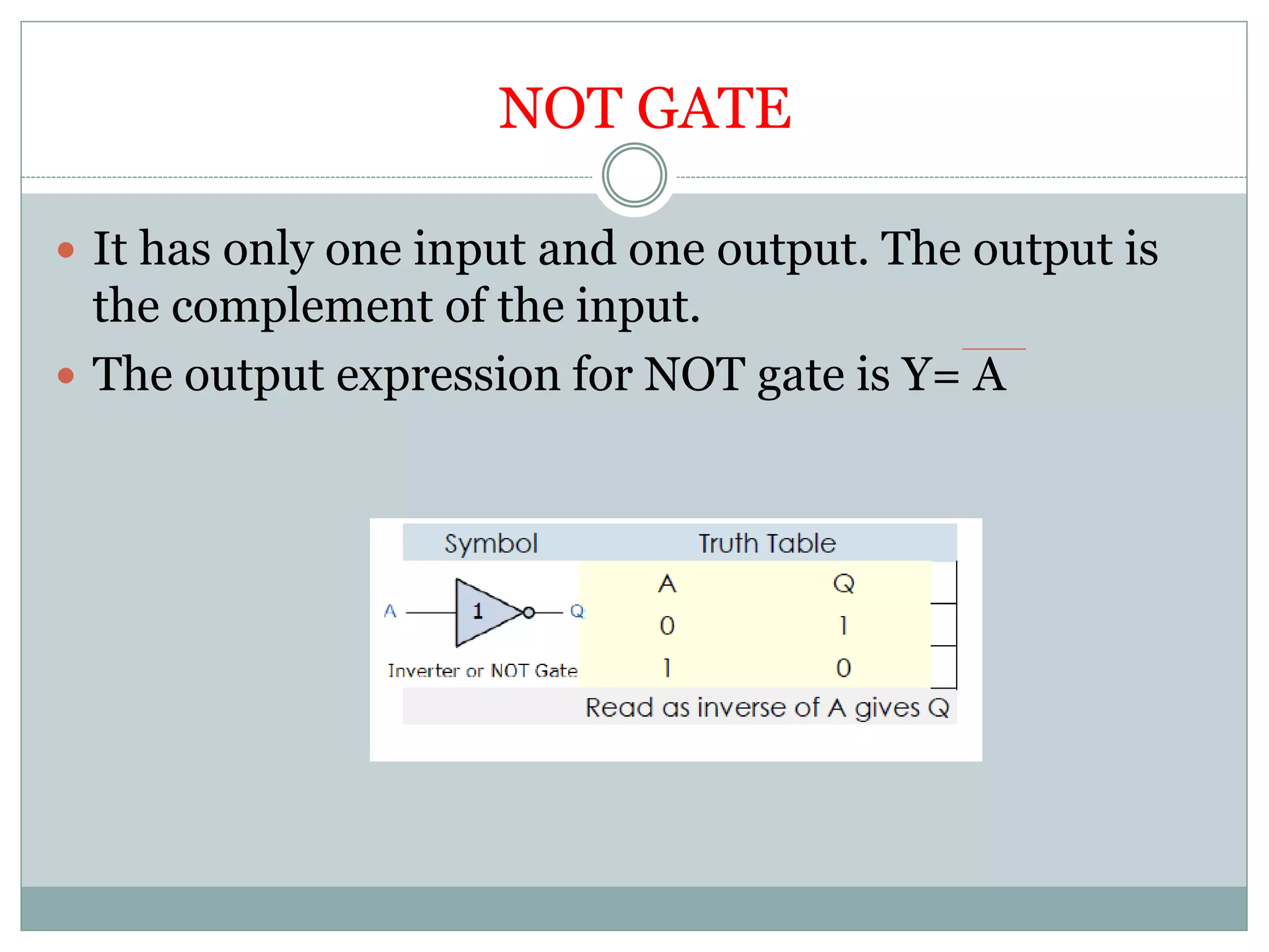
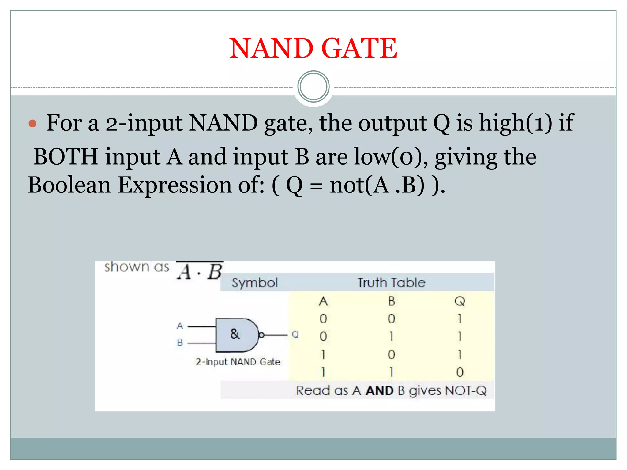
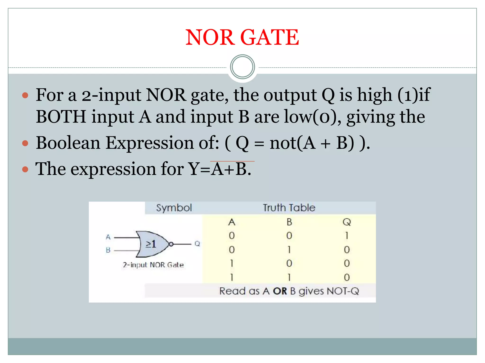
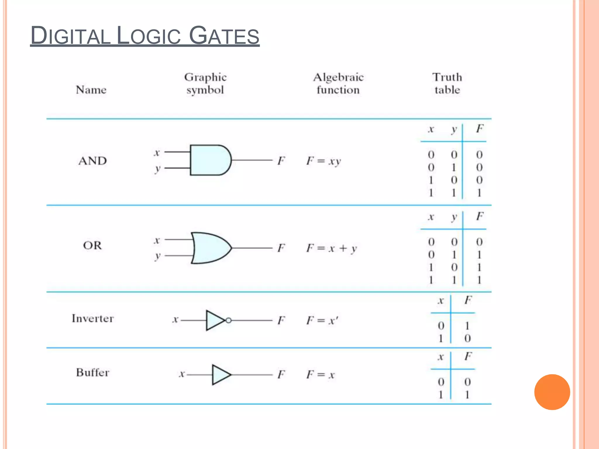
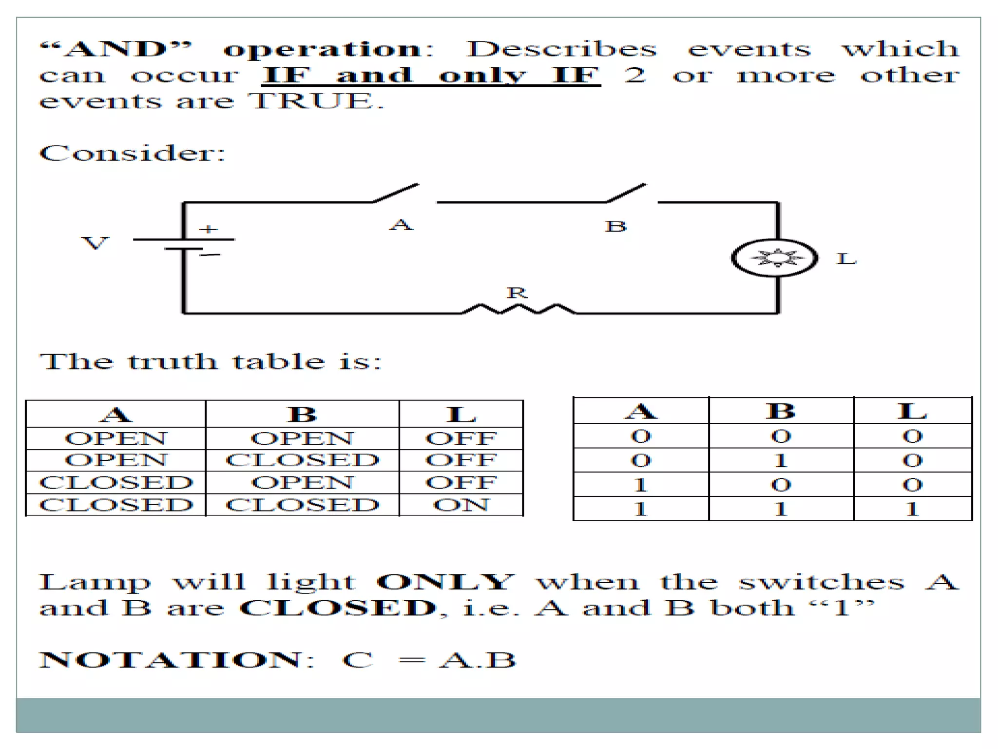
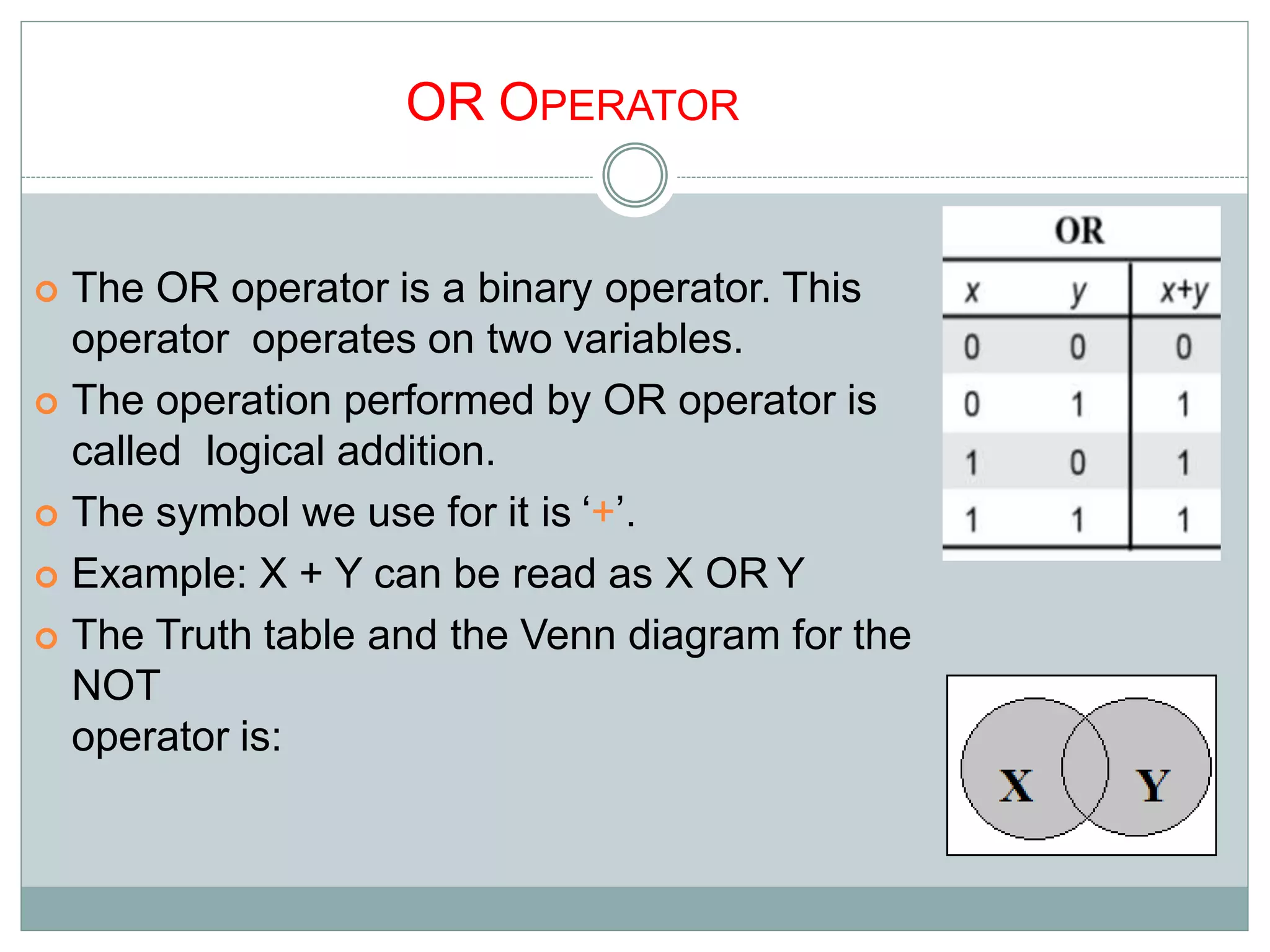
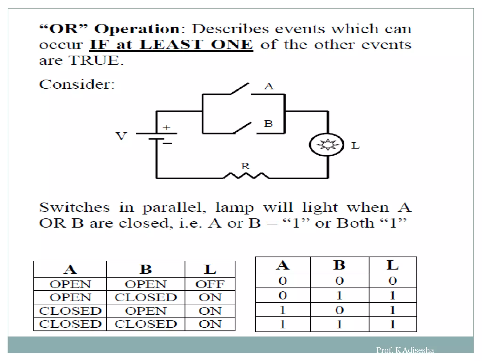
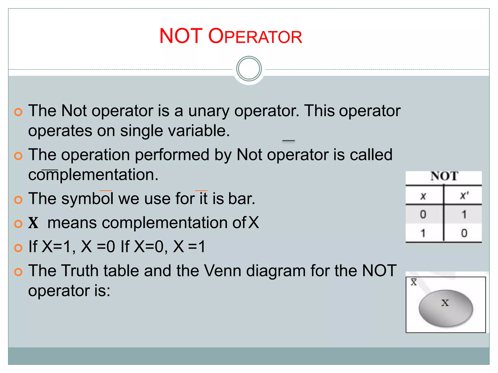
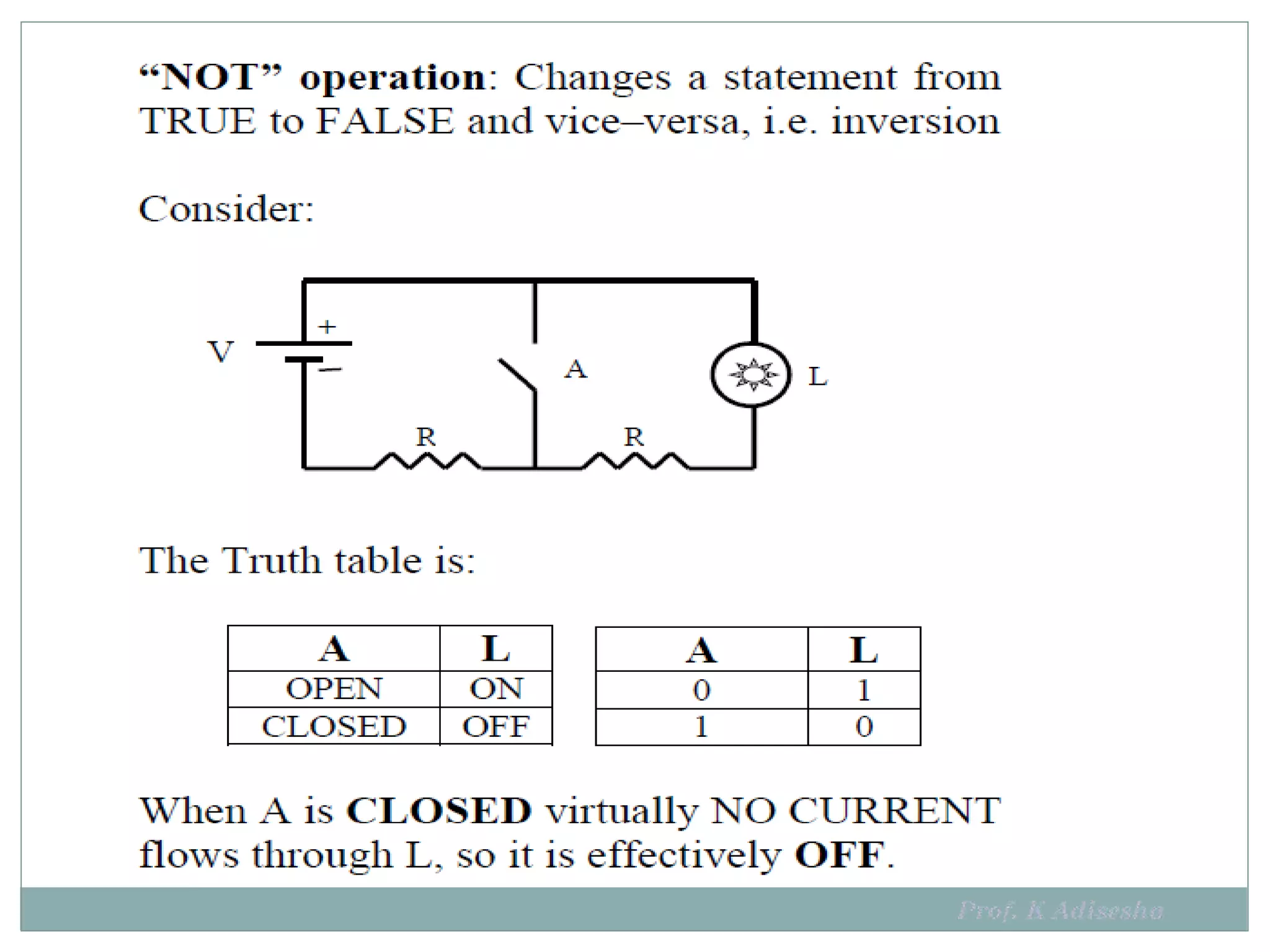
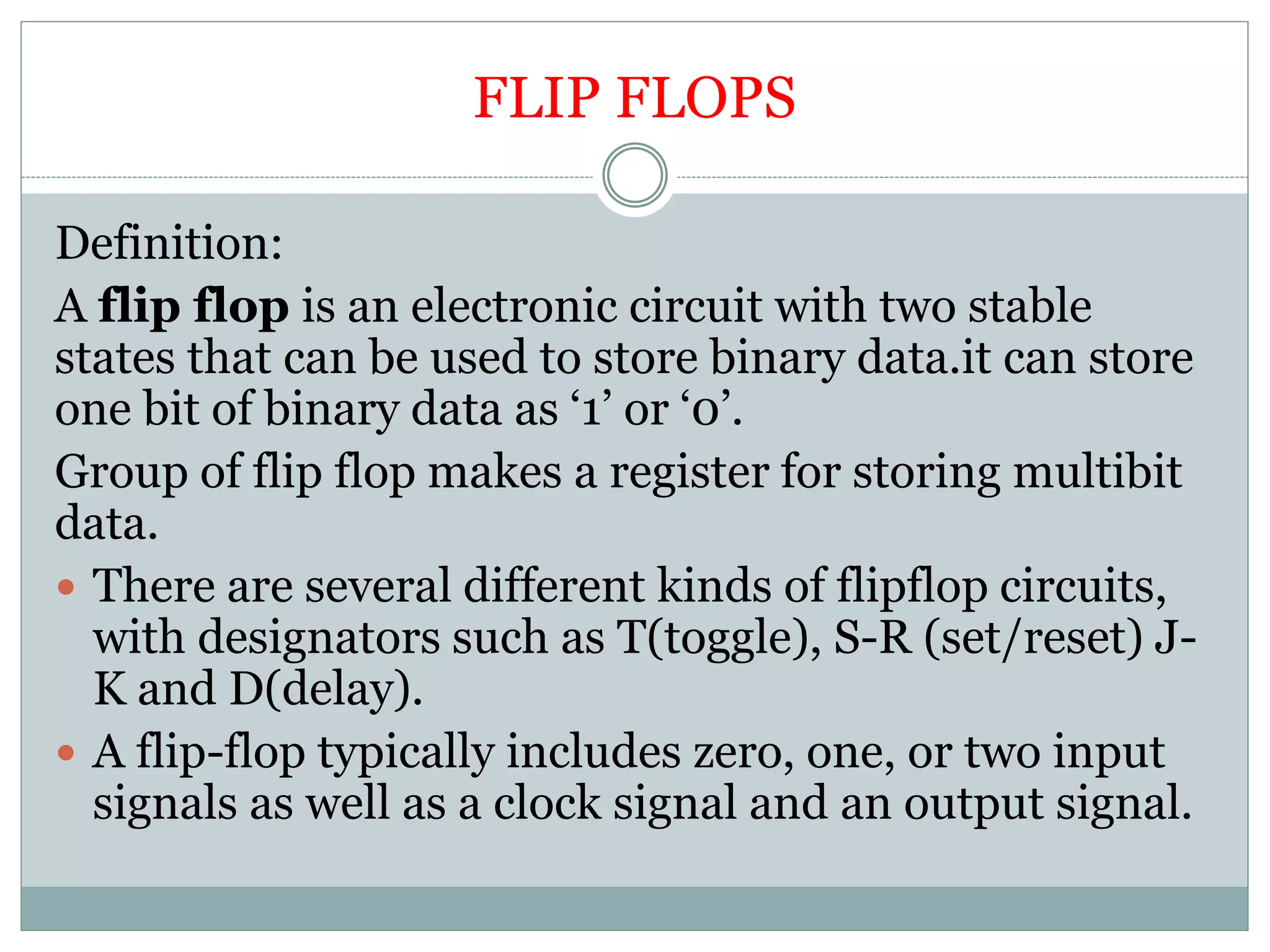
C O N T E N T S
 L O G I C G A T E S A N D I T S T Y P E S
 F L I P F L O P S A N D I T S T Y P E S
 R E G I S T E R S A N D I T S T Y P E S
 C O U N T E R S A N D I T S T Y P E S
Logic gates ,flip flop ,registers
and counters
LOGIC GATES
What are logic gates?
 A logic gate is an elementary building block of a
digital circuit. Most logic gates have two inputs and
one output.
 Gate is a circuit with one or more input and only one
output.
 Each input and output signal will be in either ‘0’ or
‘1’ state.
 In other words every terminal is in one of the two
binary conditions low (0) or high (1).
TYPES OF FLIP FLOPS
 AND Gate
 OR Gate
 NOT Gate
 NAND Gate
 NOR Gate
AND GATE
 An AND gate has two or more inputs and only one
output .
 The output is high(1) only when all the inputs are
high.If one of the input is (0) then the output is
low(0).
 The expression for
AND gate is Y=A.B
OR GATE
 For a two input OR gate the output is high(1),if one
of the input is high or else the output is low(0).
 The otput expression is Y= A+B
NOT GATE
 It has only one input and one output. The output is
the complement of the input.
 The output expression for NOT gate is Y= A
UNIVERSAL GATES
Which gates are called universal gates and why?
 NAND and NOR gates are called universal gates
 because any logic functions can be implemented
using these gates.
NAND GATE
 For a 2-input NAND gate, the output Q is high(1) if
BOTH input A and input B are low(0), giving the
Boolean Expression of: ( Q = not(A .B) ).
NOR GATE
 For a 2-input NOR gate, the output Q is high (1)if
BOTH input A and input B are low(0), giving the
 Boolean Expression of: ( Q = not(A + B) ).
 The expression for Y=A+B.
DIGITAL LOGIC GATES
Applications of Logic gates
 Burglar alarm
 Fire alarm.
OUTLINE OF BOOLEAN ALGEBRA
2
 Introduction to Boolean algebra
 History of Boolean algebra
 Logical Operators
 Basic theorems and properties of Boolean algebra
 Boolean functions
 Digital logic gates
INTRODUCTION
 An algebra that deals with binary number system
is called “Boolean Algebra”.
 It is very power in designing logic circuits used by the
processor of computer system.
 The logic gates are the building blocks of all the circuit
in a computer.
 Boolean algebra deals with truth table TRUE and
FALSE.
 If result of any logical statement or expression is always
TRUE or 1, it is called Tautology and if the result is
always FALSE or 0, it is called Fallacy
 It is also called as “Switching Algebra”
GEORGE BOOLE
 Father of Boolean algebra
 Boolean algebra derives its name from the
mathematician George Boole (1815-1864) who is
considered the “Father of symbolic logic”.
 He came up with a type of boolean algebra, the
three most basic operations of which were (and
still are) AND, OR and NOT.
 It was these three functions that formed the
basis of his premise, and were the only
operations necessary to perform comparisons
or basic mathematical functions.
George Boole (1815 - 1864)
BOOLEAN ALGEBRA
A variable used in Boolean algebra or Boolean equation
can have only one of two variables. Thetwo values are
FALSE (0) and TRUE (1)
Boolean Expression consists of
 Literal: A variable or its complement
 Product term: literals connected by •
 Sum term: literals connected by +
• A truth table is a mathematical table used in logic to
computer functional values of logical expressions.
LOGICAL OPERATORS
 There are three logical operator, AND, OR and NOT.
 These operators are now used in computer
construction known as switching circuits.
 B = {0, 1} and two binary operators, ‘+’ and ‘.’
 The rules of operations: AND, OR and NOT.
AND OPERATOR
 The AND operator is a binary operator. This operator
operates on two variables.
 The operation performed by AND operator is called
logical multiplication.
 The symbol we use for it is ‘.’
 Example: X . Y can be read as X AND Y
 The Truth table and the Venn diagram for the NOT
operator is:
7
8
OR OPERATOR
 The OR operator is a binary operator. This
operator operates on two variables.
 The operation performed by OR operator is
called logical addition.
 The symbol we use for it is ‘+’.
 Example: X + Y can be read as X OR Y
 The Truth table and the Venn diagram for the
NOT
operator is:
9
10
Prof. K Adisesha
NOT OPERATOR
 The Not operator is a unary operator. This operator
operates on single variable.
 The operation performed by Not operator is called
complementation.
 The symbol we use for it is bar.
 𝐗 means complementation ofX
 If X=1, X =0 If X=0, X =1
 The Truth table and the Venn diagram for the NOT
operator is:
11
12
POSTULATES OF BOOLEAN ALGEBRA:
The Boolean algebra has its own set of fundamental laws
which differ from the ordinary algebra. They are
 OR laws: AND laws :
A+0=A A.0= 0
A+1=1 A.A= A
A+A=A A.1 = A
A+Ā=1 A. Ā = 0
IDEMPOTENCY LAW
This law states that when a variable is combines with itself using OR or AND
operator, the output is the same variable .
27
ABSORPTION LAW: This law enables a reduction of complicated expression to a
simpler one by absorbing common terms.
EXAMPLE :
(AB+C)(AB+D)=AB+CD
AB.AB+AB.D+C.AB+C.D {A.A =A}
AB+ABD+ABC+CD
AB(1+D)+ABC+CD {1+A =1}
AB+ABC+CD
AB(1+C)+CD
AB+CD
FLIP FLOPS
Definition:
A flip flop is an electronic circuit with two stable
states that can be used to store binary data.it can store
one bit of binary data as ‘1’ or ‘0’.
Group of flip flop makes a register for storing multibit
data.
 There are several different kinds of flipflop circuits,
with designators such as T(toggle), S-R (set/reset) J-
K and D(delay).
 A flip-flop typically includes zero, one, or two input
signals as well as a clock signal and an output signal.

Logic gates ,flip flop ,registers and

  • 1.
    C O NT E N T S  L O G I C G A T E S A N D I T S T Y P E S  F L I P F L O P S A N D I T S T Y P E S  R E G I S T E R S A N D I T S T Y P E S  C O U N T E R S A N D I T S T Y P E S Logic gates ,flip flop ,registers and counters
  • 2.
    LOGIC GATES What arelogic gates?  A logic gate is an elementary building block of a digital circuit. Most logic gates have two inputs and one output.  Gate is a circuit with one or more input and only one output.  Each input and output signal will be in either ‘0’ or ‘1’ state.  In other words every terminal is in one of the two binary conditions low (0) or high (1).
  • 3.
    TYPES OF FLIPFLOPS  AND Gate  OR Gate  NOT Gate  NAND Gate  NOR Gate
  • 4.
    AND GATE  AnAND gate has two or more inputs and only one output .  The output is high(1) only when all the inputs are high.If one of the input is (0) then the output is low(0).  The expression for AND gate is Y=A.B
  • 5.
    OR GATE  Fora two input OR gate the output is high(1),if one of the input is high or else the output is low(0).  The otput expression is Y= A+B
  • 6.
    NOT GATE  Ithas only one input and one output. The output is the complement of the input.  The output expression for NOT gate is Y= A
  • 7.
    UNIVERSAL GATES Which gatesare called universal gates and why?  NAND and NOR gates are called universal gates  because any logic functions can be implemented using these gates.
  • 8.
    NAND GATE  Fora 2-input NAND gate, the output Q is high(1) if BOTH input A and input B are low(0), giving the Boolean Expression of: ( Q = not(A .B) ).
  • 9.
    NOR GATE  Fora 2-input NOR gate, the output Q is high (1)if BOTH input A and input B are low(0), giving the  Boolean Expression of: ( Q = not(A + B) ).  The expression for Y=A+B.
  • 10.
  • 11.
    Applications of Logicgates  Burglar alarm  Fire alarm.
  • 12.
    OUTLINE OF BOOLEANALGEBRA 2  Introduction to Boolean algebra  History of Boolean algebra  Logical Operators  Basic theorems and properties of Boolean algebra  Boolean functions  Digital logic gates
  • 13.
    INTRODUCTION  An algebrathat deals with binary number system is called “Boolean Algebra”.  It is very power in designing logic circuits used by the processor of computer system.  The logic gates are the building blocks of all the circuit in a computer.  Boolean algebra deals with truth table TRUE and FALSE.  If result of any logical statement or expression is always TRUE or 1, it is called Tautology and if the result is always FALSE or 0, it is called Fallacy  It is also called as “Switching Algebra”
  • 14.
    GEORGE BOOLE  Fatherof Boolean algebra  Boolean algebra derives its name from the mathematician George Boole (1815-1864) who is considered the “Father of symbolic logic”.  He came up with a type of boolean algebra, the three most basic operations of which were (and still are) AND, OR and NOT.  It was these three functions that formed the basis of his premise, and were the only operations necessary to perform comparisons or basic mathematical functions. George Boole (1815 - 1864)
  • 15.
    BOOLEAN ALGEBRA A variableused in Boolean algebra or Boolean equation can have only one of two variables. Thetwo values are FALSE (0) and TRUE (1) Boolean Expression consists of  Literal: A variable or its complement  Product term: literals connected by •  Sum term: literals connected by + • A truth table is a mathematical table used in logic to computer functional values of logical expressions.
  • 16.
    LOGICAL OPERATORS  Thereare three logical operator, AND, OR and NOT.  These operators are now used in computer construction known as switching circuits.  B = {0, 1} and two binary operators, ‘+’ and ‘.’  The rules of operations: AND, OR and NOT.
  • 17.
    AND OPERATOR  TheAND operator is a binary operator. This operator operates on two variables.  The operation performed by AND operator is called logical multiplication.  The symbol we use for it is ‘.’  Example: X . Y can be read as X AND Y  The Truth table and the Venn diagram for the NOT operator is: 7
  • 18.
  • 19.
    OR OPERATOR  TheOR operator is a binary operator. This operator operates on two variables.  The operation performed by OR operator is called logical addition.  The symbol we use for it is ‘+’.  Example: X + Y can be read as X OR Y  The Truth table and the Venn diagram for the NOT operator is: 9
  • 20.
  • 21.
    NOT OPERATOR  TheNot operator is a unary operator. This operator operates on single variable.  The operation performed by Not operator is called complementation.  The symbol we use for it is bar.  𝐗 means complementation ofX  If X=1, X =0 If X=0, X =1  The Truth table and the Venn diagram for the NOT operator is: 11
  • 22.
  • 24.
    POSTULATES OF BOOLEANALGEBRA: The Boolean algebra has its own set of fundamental laws which differ from the ordinary algebra. They are  OR laws: AND laws : A+0=A A.0= 0 A+1=1 A.A= A A+A=A A.1 = A A+Ā=1 A. Ā = 0
  • 26.
    IDEMPOTENCY LAW This lawstates that when a variable is combines with itself using OR or AND operator, the output is the same variable .
  • 27.
  • 28.
    ABSORPTION LAW: Thislaw enables a reduction of complicated expression to a simpler one by absorbing common terms.
  • 29.
    EXAMPLE : (AB+C)(AB+D)=AB+CD AB.AB+AB.D+C.AB+C.D {A.A=A} AB+ABD+ABC+CD AB(1+D)+ABC+CD {1+A =1} AB+ABC+CD AB(1+C)+CD AB+CD
  • 30.
    FLIP FLOPS Definition: A flipflop is an electronic circuit with two stable states that can be used to store binary data.it can store one bit of binary data as ‘1’ or ‘0’. Group of flip flop makes a register for storing multibit data.  There are several different kinds of flipflop circuits, with designators such as T(toggle), S-R (set/reset) J- K and D(delay).  A flip-flop typically includes zero, one, or two input signals as well as a clock signal and an output signal.