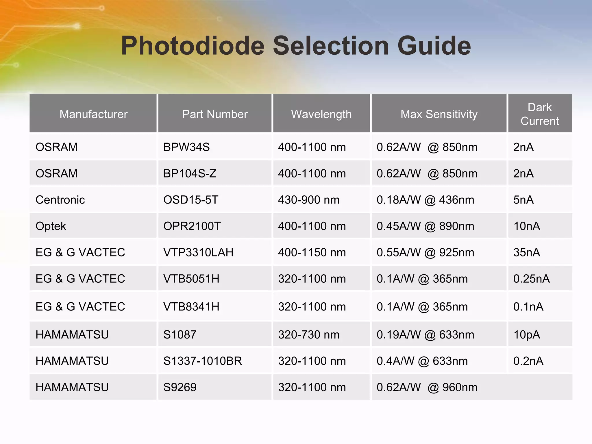
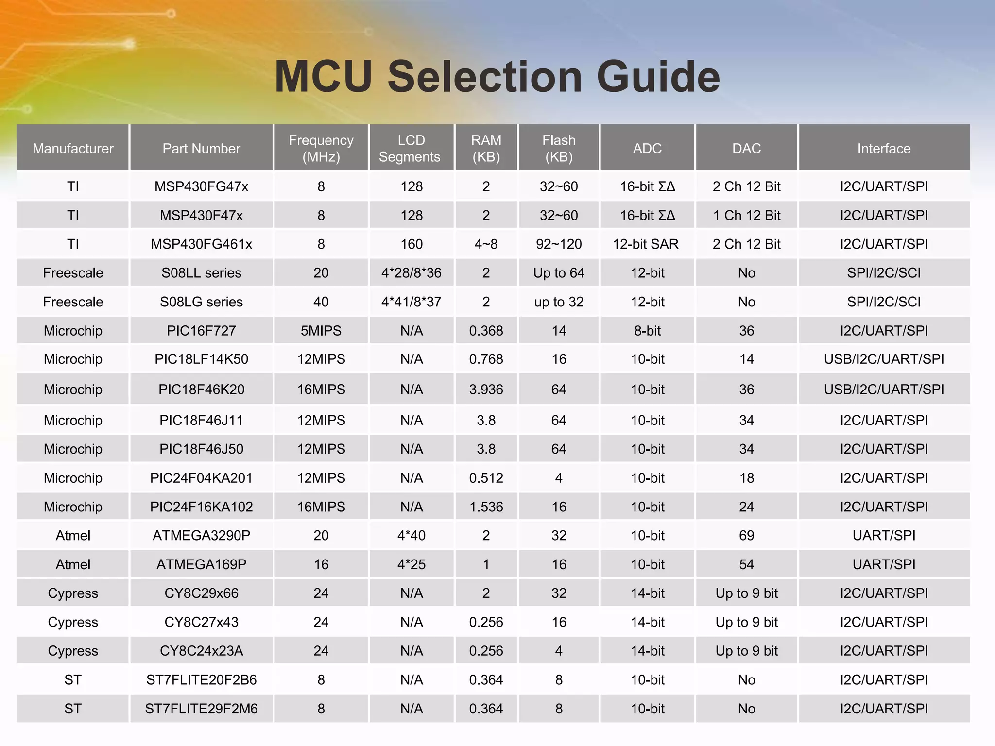
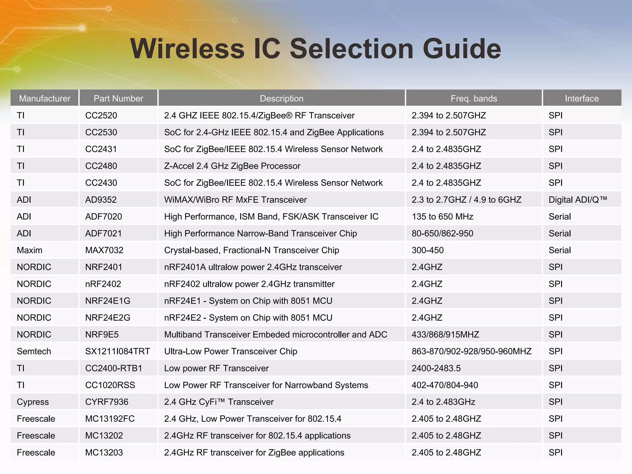
This document introduces solutions for handheld laser barcode scanners. It provides recommendations for core chips, laser diodes, drivers, motors, wireless modules, and other peripherals suitable for barcode scanning applications. Tables list part numbers and specifications for various components from manufacturers like TI, Microchip, Cypress, and Nordic. Additional resources are provided for technical support and purchasing components.
9. Laser Diode Driver Selection Guide Manufacturer Part Number Description Supply Voltage Laser Drive Current Laser Components IC-WKL 2.4V CW Laser Diode Driver 2.4 to 6V 70mA Laser Components IC-WKM M-TYPE CW Laser Diode Driver 3.6 to 15V 70mA Laser Components IC-WKN 15V CW Laser Diode Driver 2.4 to 15V 300mA ADI ADN2531 Differential Laser Diode Driver 3 to 3.6V 100mA ADI ADN2841 Laser Diode Driver 5V 100mA ADI ADN2870 Laser Diode Driver 5V 100mA TI ONET1101L 11.3 Gbps Laser Diode Driver 3.3V 100mA TI ONET4211LD 155 Mbps to 4.25 Gbps Laser Driver 3.3V 100mA
10.
11. Motor Driver Selection Guide Manufacturer Part Number Description Supply Voltage Output Current Intersil HIP4020IBZ Full Bridge Driver with Integrated 0.5A Power FETs for Small 3V, 5V and 12V DC Motors 3 to 12V 0.5A Linear LTC1157 3.3V Dual Micropower High-Side/Low-Side MOSFET Driver 3.3/5V -- Linear LT1910 Protected High Side MOSFET Driver 8 to 48V -- Linear LTC1156 Quad High Side Micropower MOSFET Driver 4.5 to 18V -- Linear LTC1154 High-Side Micropower MOSFET Driver 4.5 to 18V -- Linear LT1161 Quad Protected High-Side MOSFET Driver 8 to 48V -- NS LM5109 High Voltage 1A Peak Half Bridge Gate Driver 8 to 14V 1A TI TPS2811D Inverting Dual High-Speed MOSFET Drivers 4to 40V 2A TI TPS2814 Inverting Dual High-Speed MOSFET Drivers 4to 14V 2A TI TPS2816 Inverting High Speed MOSFET Driver 4to 14V 2A
14. MCU Selection Guide Manufacturer Part Number Frequency (MHz) LCD Segments RAM (KB) Flash (KB) ADC DAC Interface TI MSP430FG47x 8 128 2 32~60 16-bit ΣΔ 2 Ch 12 Bit I2C/UART/SPI TI MSP430F47x 8 128 2 32~60 16-bit ΣΔ 1 Ch 12 Bit I2C/UART/SPI TI MSP430FG461x 8 160 4~8 92~120 12-bit SAR 2 Ch 12 Bit I2C/UART/SPI Freescale S08LL series 20 4*28/8*36 2 Up to 64 12-bit No SPI/I2C/SCI Freescale S08LG series 40 4*41/8*37 2 up to 32 12-bit No SPI/I2C/SCI Microchip PIC16F727 5MIPS N/A 0.368 14 8-bit 36 I2C/UART/SPI Microchip PIC18LF14K50 12MIPS N/A 0.768 16 10-bit 14 USB/I2C/UART/SPI Microchip PIC18F46K20 16MIPS N/A 3.936 64 10-bit 36 USB/I2C/UART/SPI Microchip PIC18F46J11 12MIPS N/A 3.8 64 10-bit 34 I2C/UART/SPI Microchip PIC18F46J50 12MIPS N/A 3.8 64 10-bit 34 I2C/UART/SPI Microchip PIC24F04KA201 12MIPS N/A 0.512 4 10-bit 18 I2C/UART/SPI Microchip PIC24F16KA102 16MIPS N/A 1.536 16 10-bit 24 I2C/UART/SPI Atmel ATMEGA3290P 20 4*40 2 32 10-bit 69 UART/SPI Atmel ATMEGA169P 16 4*25 1 16 10-bit 54 UART/SPI Cypress CY8C29x66 24 N/A 2 32 14-bit Up to 9 bit I2C/UART/SPI Cypress CY8C27x43 24 N/A 0.256 16 14-bit Up to 9 bit I2C/UART/SPI Cypress CY8C24x23A 24 N/A 0.256 4 14-bit Up to 9 bit I2C/UART/SPI ST ST7FLITE20F2B6 8 N/A 0.364 8 10-bit No I2C/UART/SPI ST ST7FLITE29F2M6 8 N/A 0.364 8 10-bit No I2C/UART/SPI
15. Wireless IC Selection Guide Manufacturer Part Number Description Freq. bands Interface TI CC2520 2.4 GHZ IEEE 802.15.4/ZigBee® RF Transceiver 2.394 to 2.507GHZ SPI TI CC2530 SoC for 2.4-GHz IEEE 802.15.4 and ZigBee Applications 2.394 to 2.507GHZ SPI TI CC2431 SoC for ZigBee/IEEE 802.15.4 Wireless Sensor Network 2.4 to 2.4835GHZ SPI TI CC2480 Z-Accel 2.4 GHz ZigBee Processor 2.4 to 2.4835GHZ SPI TI CC2430 SoC for ZigBee/IEEE 802.15.4 Wireless Sensor Network 2.4 to 2.4835GHZ SPI ADI AD9352 WiMAX/WiBro RF MxFE Transceiver 2.3 to 2.7GHZ / 4.9 to 6GHZ Digital ADI/Q™ ADI ADF7020 High Performance, ISM Band, FSK/ASK Transceiver IC 135 to 650 MHz Serial ADI ADF7021 High Performance Narrow-Band Transceiver Chip 80-650/862-950 Serial Maxim MAX7032 Crystal-based, Fractional-N Transceiver Chip 300-450 Serial NORDIC NRF2401 nRF2401A ultralow power 2.4GHz transceiver 2.4GHZ SPI NORDIC nRF2402 nRF2402 ultralow power 2.4GHz transmitter 2.4GHZ SPI NORDIC NRF24E1G nRF24E1 - System on Chip with 8051 MCU 2.4GHZ SPI NORDIC NRF24E2G nRF24E2 - System on Chip with 8051 MCU 2.4GHZ SPI NORDIC NRF9E5 Multiband Transceiver Embeded microcontroller and ADC 433/868/915MHZ SPI Semtech SX1211I084TRT Ultra-Low Power Transceiver Chip 863-870/902-928/950-960MHZ SPI TI CC2400-RTB1 Low power RF Transceiver 2400-2483.5 SPI TI CC1020RSS Low Power RF Transceiver for Narrowband Systems 402-470/804-940 SPI Cypress CYRF7936 2.4 GHz CyFi™ Transceiver 2.4 to 2.483GHz SPI Freescale MC13192FC 2.4 GHz, Low Power Transceiver for 802.15.4 2.405 to 2.48GHZ SPI Freescale MC13202 2.4GHz RF transceiver for 802.15.4 applications 2.405 to 2.48GHZ SPI Freescale MC13203 2.4GHz RF transceiver for ZigBee applications 2.405 to 2.48GHZ SPI
16. Peripheral Solution Block Farnell Newark Power Management ICS Click Click EEPROM Click Click Flash Memory Click Click Battery Click Click Amplifier Click Click DC Motor Click Click DC Motor Driver Click Click Laser Diode Click Click Laser Driver Click Click Interface & Driver Click Click
17.
Editor's Notes
Handheld Laser Barcode Scanners
Welcome to the training module on Handheld Laser Barcode Scanners. This training module will introduce a solution for handheld laser barcode scanner and recommended some related components.
Barcodes allow you to easily and accurately track items and reference data associated with those items. From Wikipedia, a barcode is an optical machine-readable representation of data, which shows certain data on certain products. The barcode doesn't contain descriptive data, but just a reference number. A barcode is a series of varying width vertical lines (called bars) and spaces. This Symbology defines the technical details of a particular type of barcode: the width of the bars, character set, method of encoding, checksum specifications, etc. There are lots of different bar codes. Some bar codes are numeric only whiles other have both letters and numbers. Some bar codes are fixed length whils others are not. 2D barcode, also called matrix code, is a two-dimensional way of representing information. This barcode has more data representation capability.
A barcode scanner is designed specially to read barcodes printed on various surfaces. As we said before, a barcode is an optical machine readable data, so it is read by an optical scanner that measures the relative widths of the bars and spaces, translates the different patterns back into regular characters. The black lines of a barcode reflect less light, and more light is reflected by the white spaces. Many different types of bar code scanning machines exist, but they all work on the same fundamental principles. A optical sensor receives reflections to obtain analog waveforms. Then the analog signal is converted into a digital signal via an ADC. Finally, the digital signal is sent to microcontroller for further process.
There are three basic types of bar code scanners: wand, charge couple device, and laser. The wand scanner is the simplest and least expensive scanner available. It is durable and contains no moving parts. It must, however, come into contact with the bar code, which can present a challenge. So it must be held at the proper angle and moved at the proper speed. The CCD, or "Charge Couple Device," is another common scanner. Similarly, the CCD scanner does not have any moving parts thus it is reliable and less prone to failure. It is able to read bar codes quickly and easily, but it has a short read range, and must be held no more than 1 to 3 inches from the bar code. The laser scanner is perhaps the most popular bar code input device. A laser scanner need not be close to the bar code to do its job. A standard range laser scanner can read a bar code from about 6 to 24 inches away. But compared to other two scanners, it is more expensive.
Handheld laser barcode scanners are portable barcode scanning devices featured with advantages such as long scanning distance, fast scanning speed, high motion tolerance and wide scanning range because of its laser light source. It is widely used in commodity circulation, library management, mail management, warehouses, factories, supermarkets and other business. Now let us look at how a laser barcode scanner works. The laser scanner works by sending a low energy light beam or laser beam to read the spacing between a pattern on the image one space at a time. The beam is moving back and forth by using a mobile mirror which causes a blinking effect. You can usually see the red line moving over the barcode. The reflection comes back and is then read by the fixed mirror in the scanner. The scanner then generates analog and digital signals that match the pattern. A barcode reader decoder then processes the information and sends it through the data communications interface.
A handheld laser barcode scanner has a switch button. When the switch is triggered by a user, it sends out a trigger signal to MCU. Then the MCU instruct the driver circuit to drive a laser diode. Meanwhile, the motor driver is also activated to drive the motor to rotate the polygon mirror. Laser beams emitted from the laser diode hit the polygon mirror and scan a barcode. The light-receiving element (photodiode) receives the light of diffuse reflection from the barcode. The diffuse reflection looks like an analog waveform. The barcode scanner amplifies the analog signal using an amplifier and converts the waveform from analog to digital (A/D conversion). The barcode scanner identifies the narrow/wide bars and narrow/wide spaces using digital signals. The barcode scanner converts the signal combination of the bars and spaces into data according to the barcode rules (decoding). It outputs the decoded data to the external unit through RS-232C or a wireless interface.
A hand held barcode scanner employs a laser diode as its light source for an efficient and compact construction. The advantage of laser light is that it can be focused and collimated to a very small beam. Because the light is coherent, the beam will not spread much over a given distance. Therefore, the diameter of the beam will remain small enough to resolve the wide and narrow bars of the bar code even if the reading distance varies. The visible laser diodes are selected with the wavelength from 630nm to 670nm, so the color of the light beam is red. Because we design a handheld device, the power consumption of the laser diodes is one of requirements.
For driving a laser diode, a suitable circuit is required. A laser diodes behaves like usual PN-diode which is biased in the forward direction, so the driver must provide proper biased current. The excessive reverse voltage or forward current can easily destroy it. In our design, the laser diode is driven by a microcontroller through an integrated driver. The laser diode driver should be able to protect the laser diode against transients and keeps the output power stable over a wide supply voltage range.
The ONET4211LD is a laser driver for multiple fiber optic applications up to 4.25 Gbps. The device accepts CML input data and provides bias and modulation currents for driving a laser diode. Also provided are automatic power control (APC), temperature compensation of modulation current, fault detection, and current monitor features. This laser driver circuit consists of a high-speed data path and a bias-and-control block. The function of the data path is to buffer the input data and then modulate the laser diode current according to the input data stream. The bias-and-control block generates the laser diode bias current, maintains constant optical output power, generates a modulation current that can be temperature compensated, and controls power on during start-up and shutdown after failure detection.
In our solution, a small DC motor controls to rotate the polygon mirror. Then a motor drive is used to drive the small DC motor.
The photo detector can be a silicon photovoltaic cell, a photodiode or an optical transistor, used to convert the light reflected by the barcode into electric signals. In our design, we select a photodiode. The photodiode generates voltage waveform to represents the bar and space pattern in the barcode. We select the parts based on three parameters, wavelength, maximum sensitivity, and dark current.
Here is overview of BPW34S photodiode from OSRAM.
A handheld laser scanner can use an 8/16-bit low-power microcontroller to analyze barcode information. The MCU analyzes the datastream from the photo detector, isolates any section that appears to be valid data, decodes the barcode symbols, and sends the result to the host computer via a RS232 interface or wireless interface.I 2 C
The wireless transmitter is an optional module. It is used to transmit barcode information to a computer through wireless connection.
The tale lists out some additional components which are used in laser barcode scanner solution. The power management part can be a DC/DC converter or LDO regulator that provides a wide range of input voltage, stable output voltage, and low standby current. EEPROM or flash memory is used to store barcode information. As it is a handheld device, battery is used as power source which may be a a rechargeable battery with small size, low weight, large capacity and long service life. The amplifier is used to amplify the small signals coming from the photo detector. The interface and driver component is used to communicate the barcode scanner with the host computer.
Thank you for taking the time to view this presentation on Handheld Laser Barcode Scanners. If you would like to learn more or go on to purchase some of these devices, you may either click on the part list link, or simply call our sales hotline. For more design resources you may either visit the element14 site, or if you would prefer to speak to someone live, please call our hotline number, or even use our ‘live chat’ online facility. You may visit Element 14 e-community to post your questions.