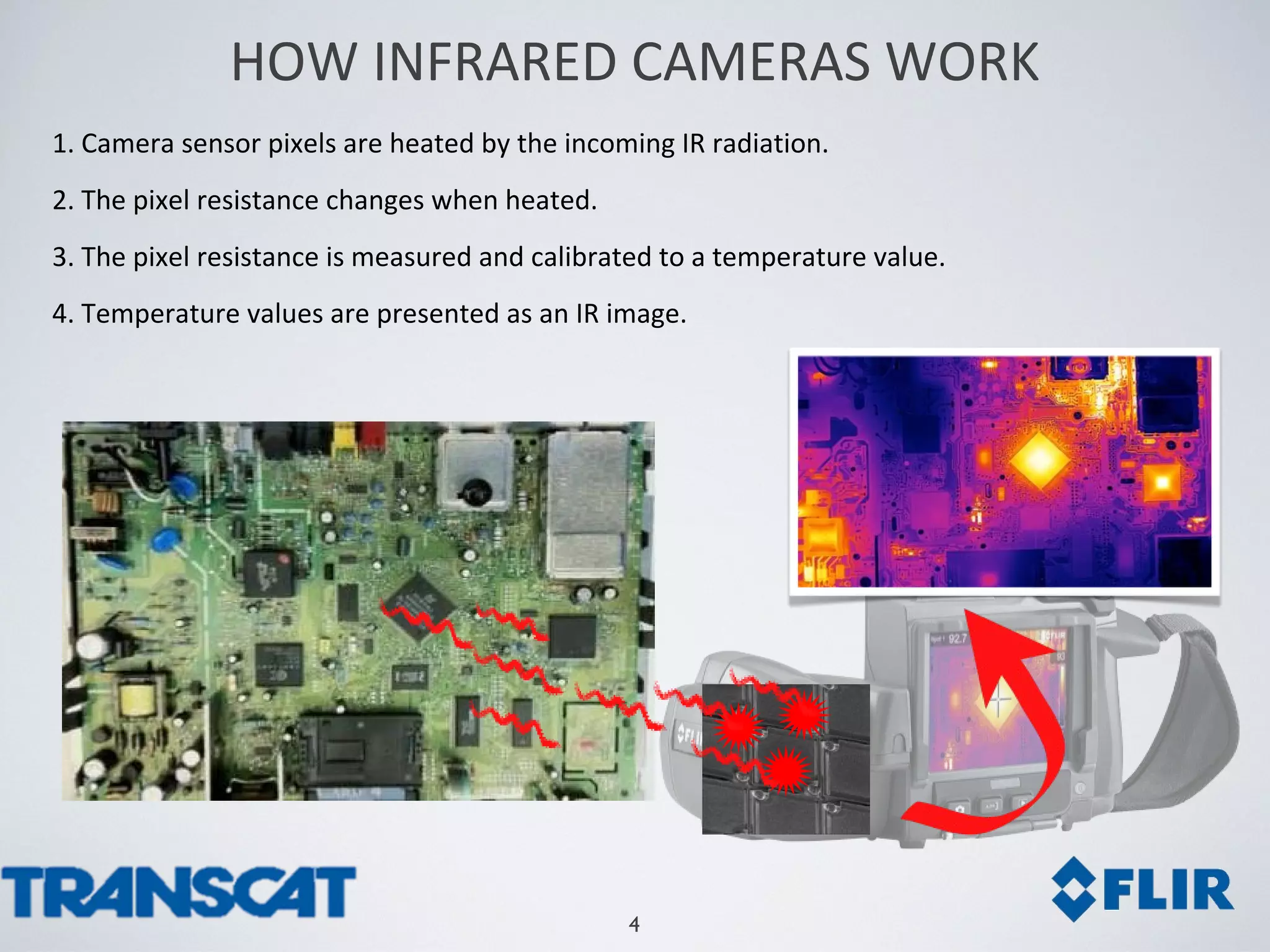
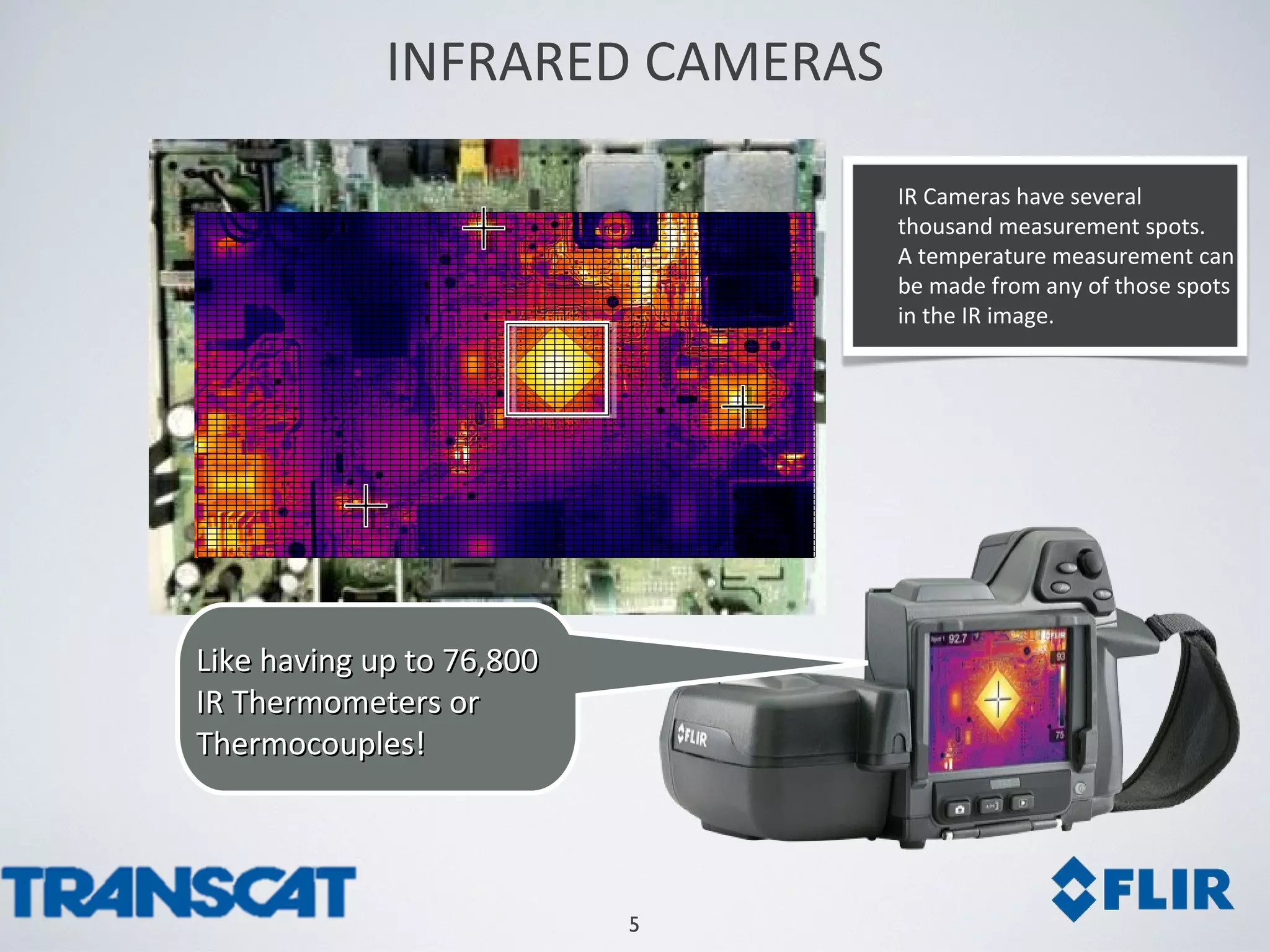
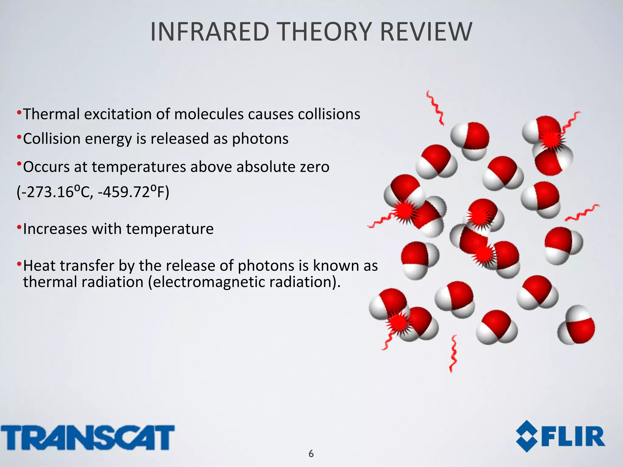
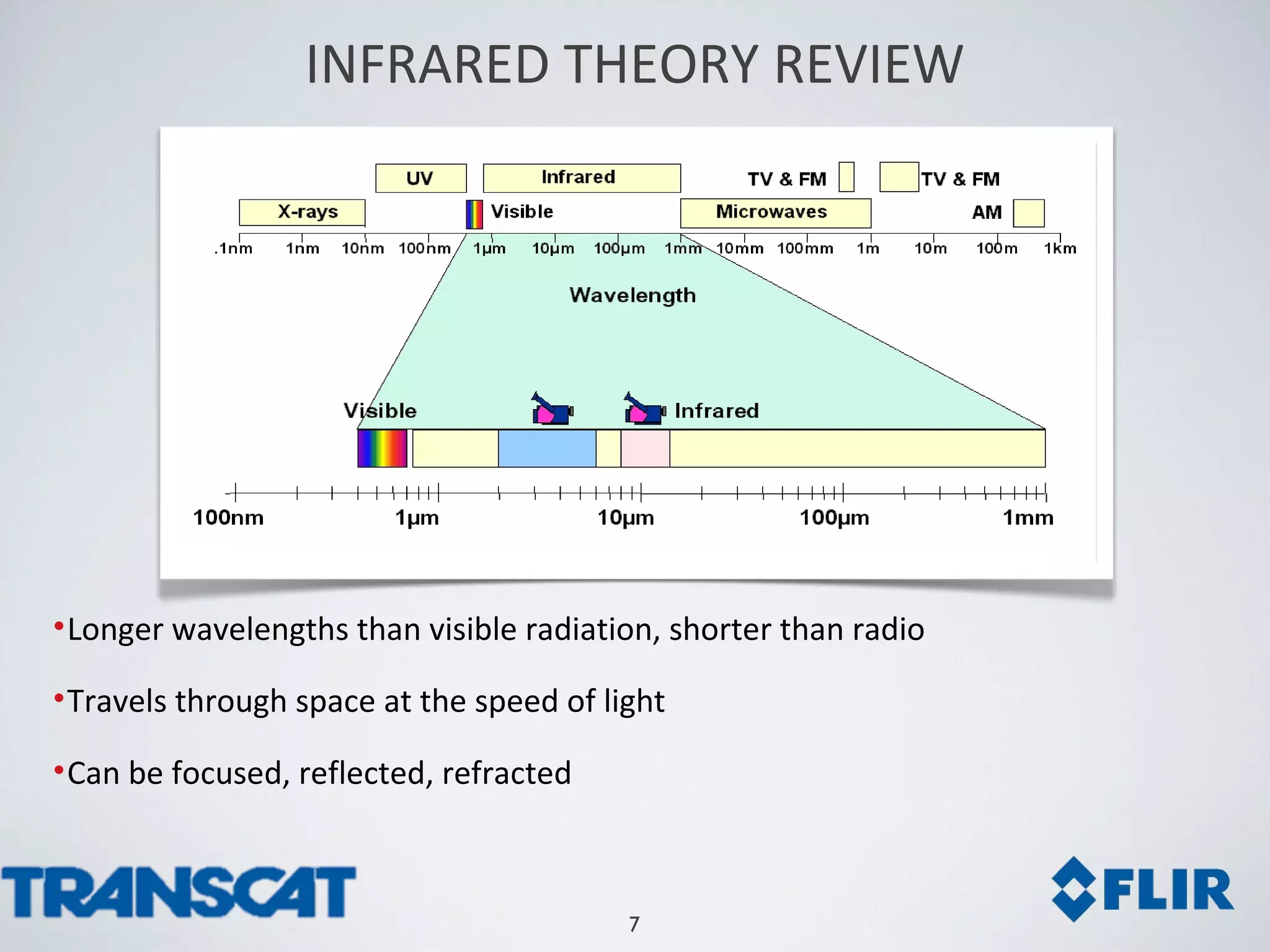
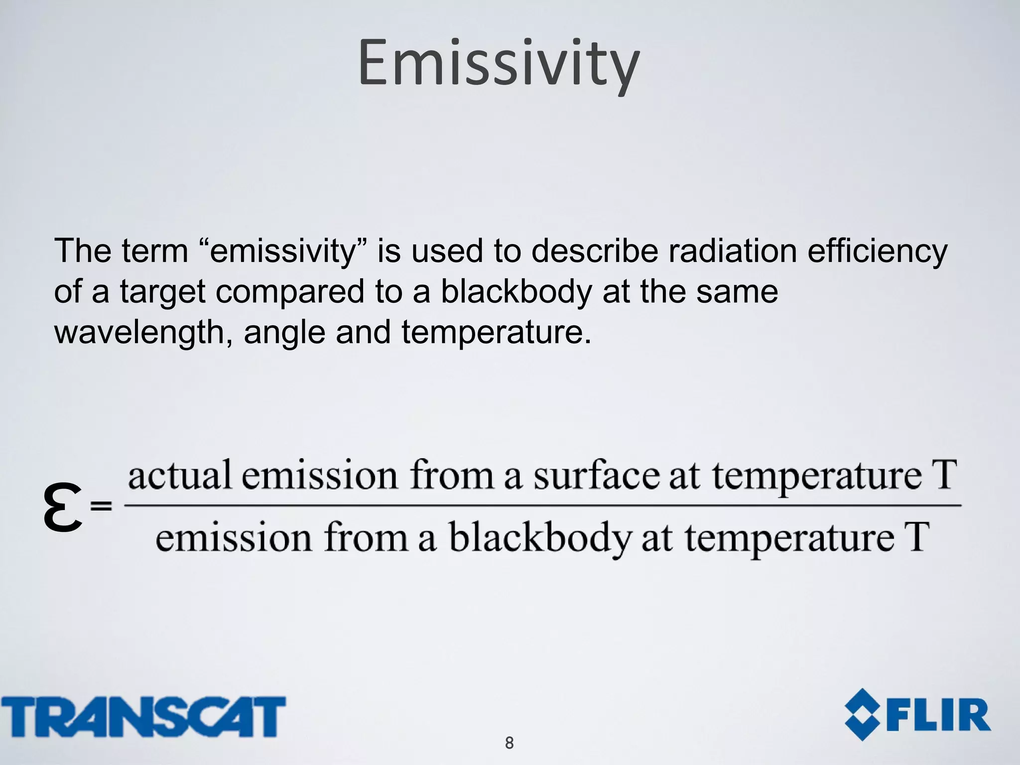
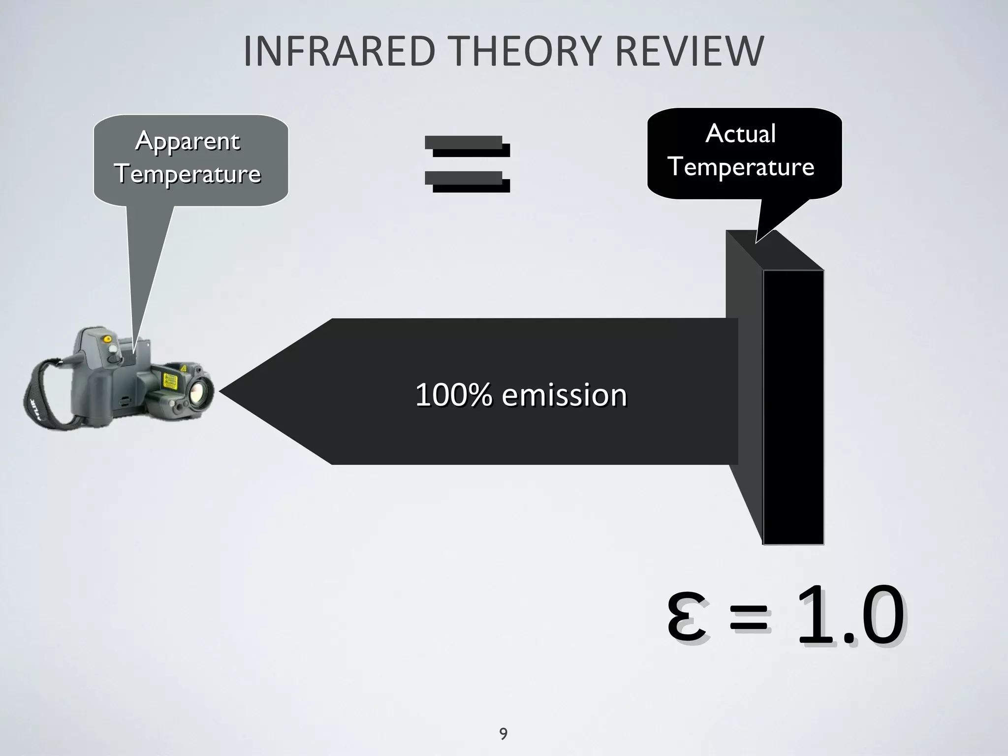
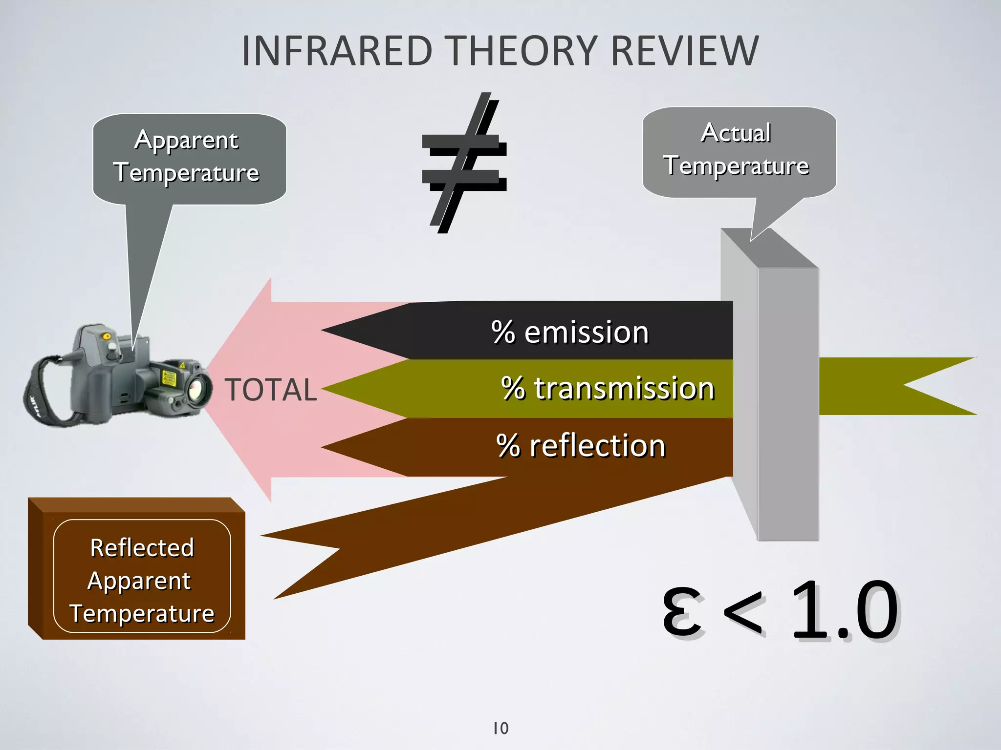
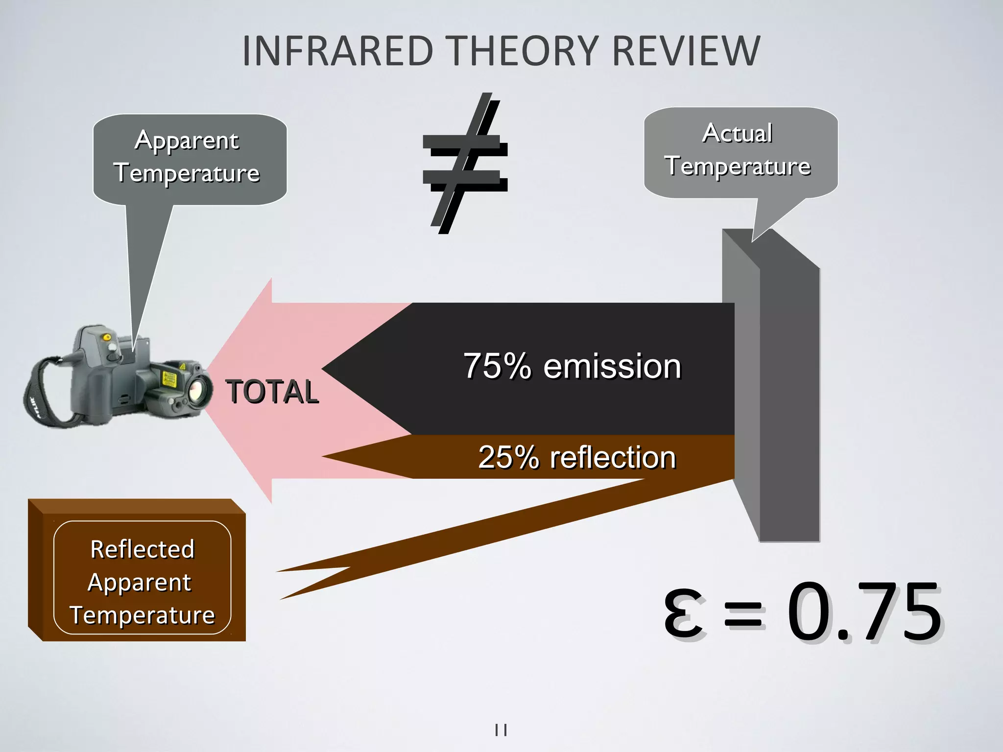
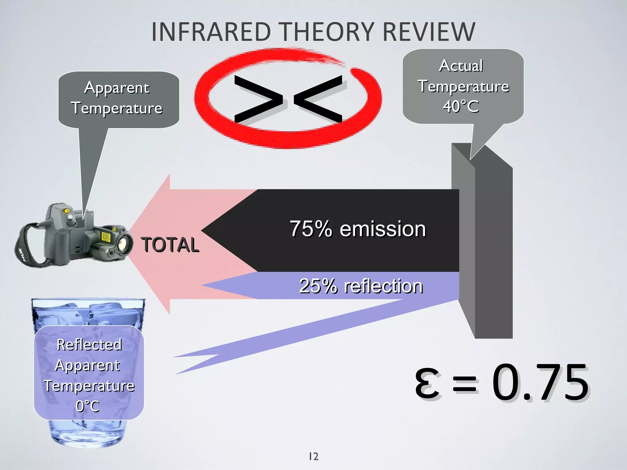
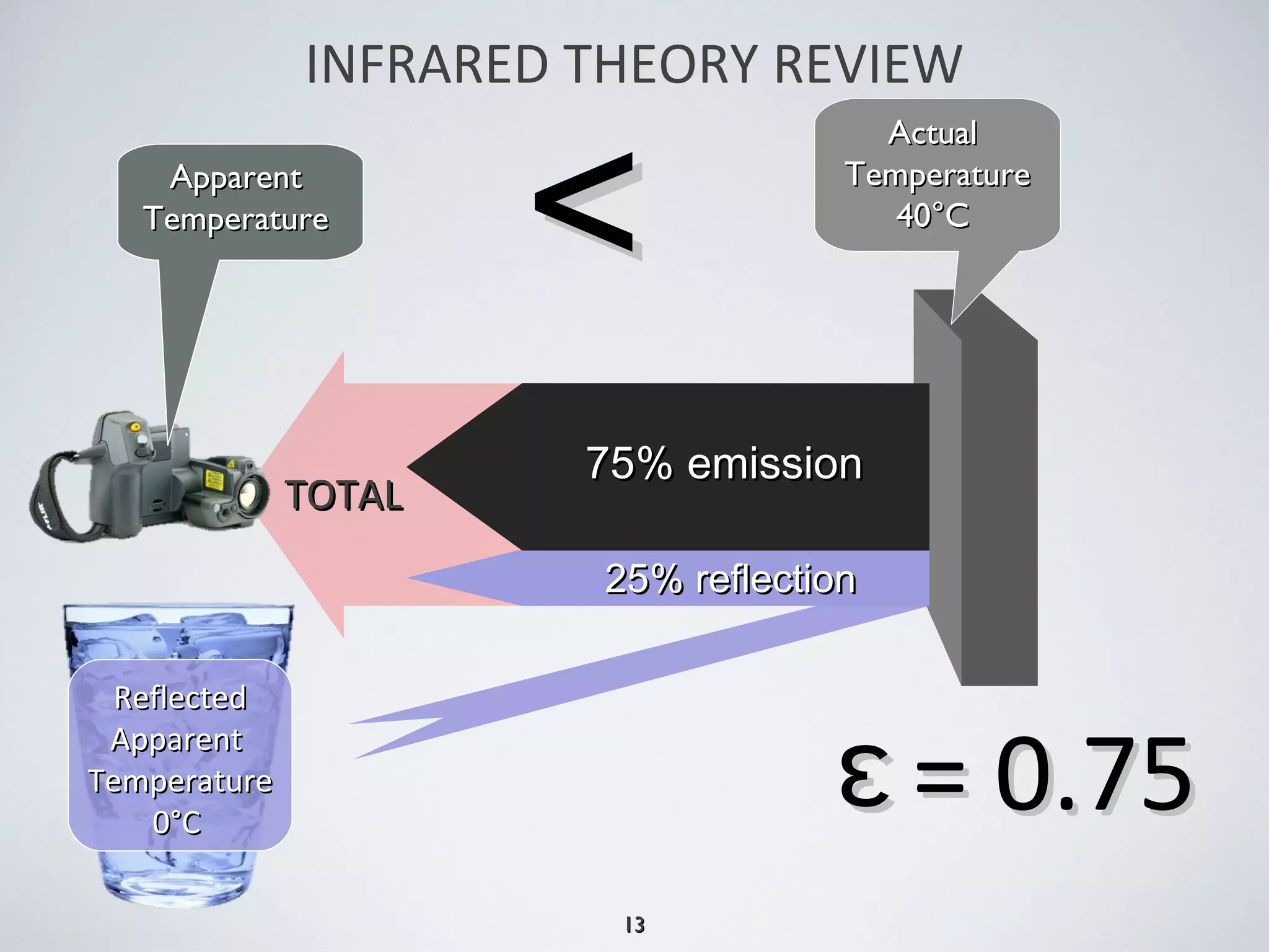
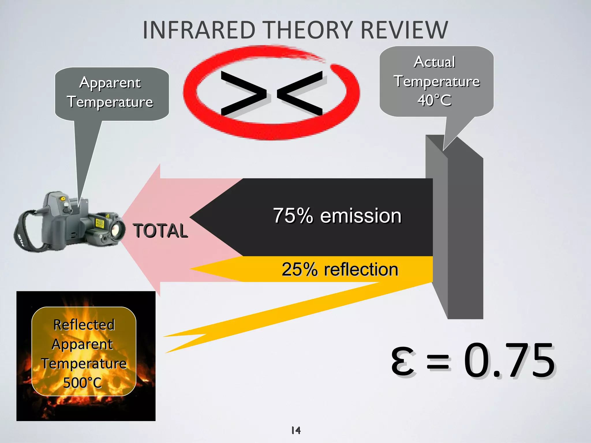
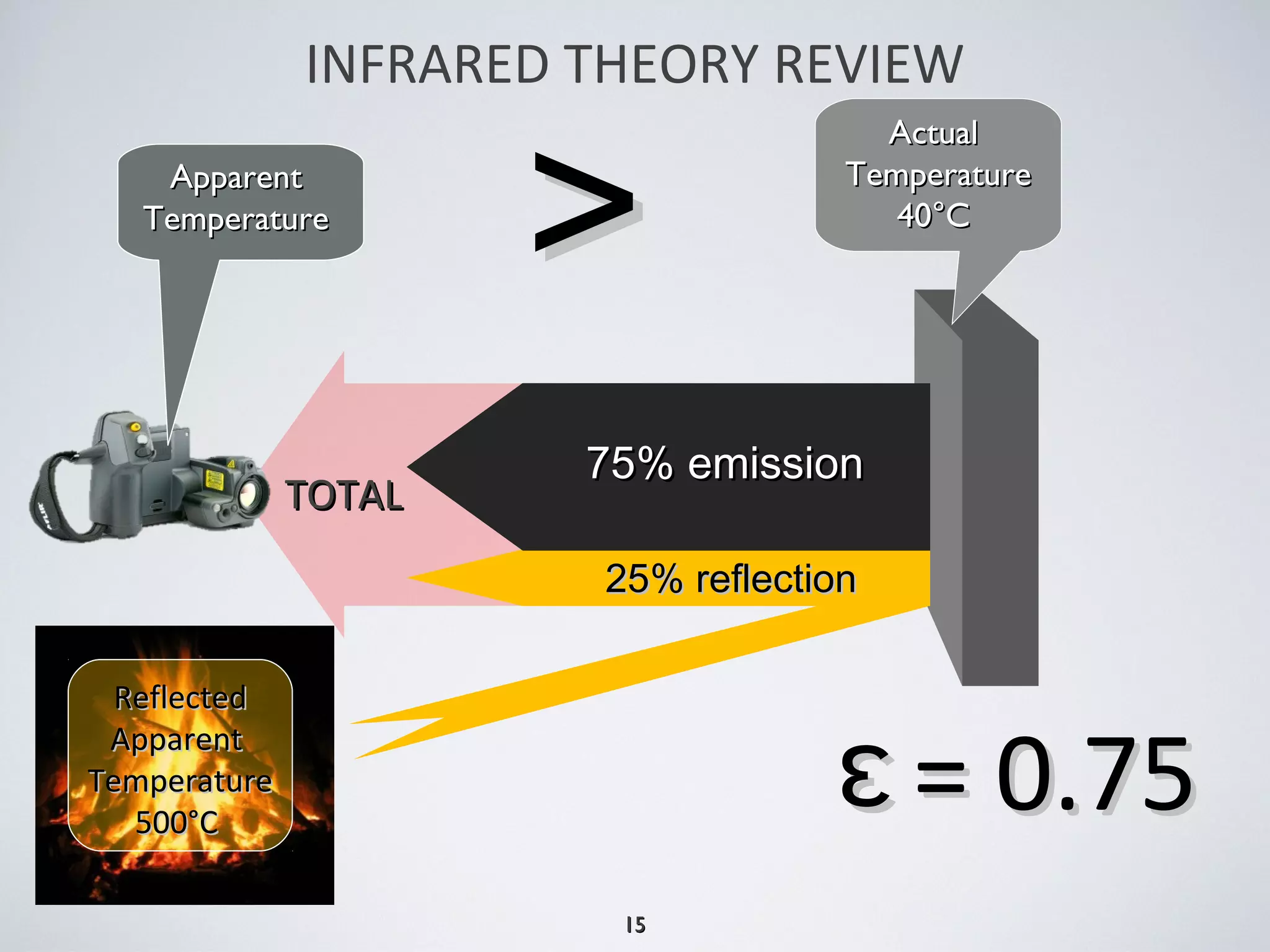
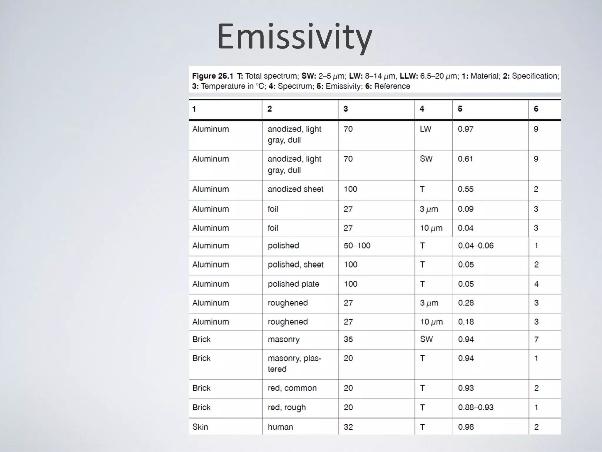
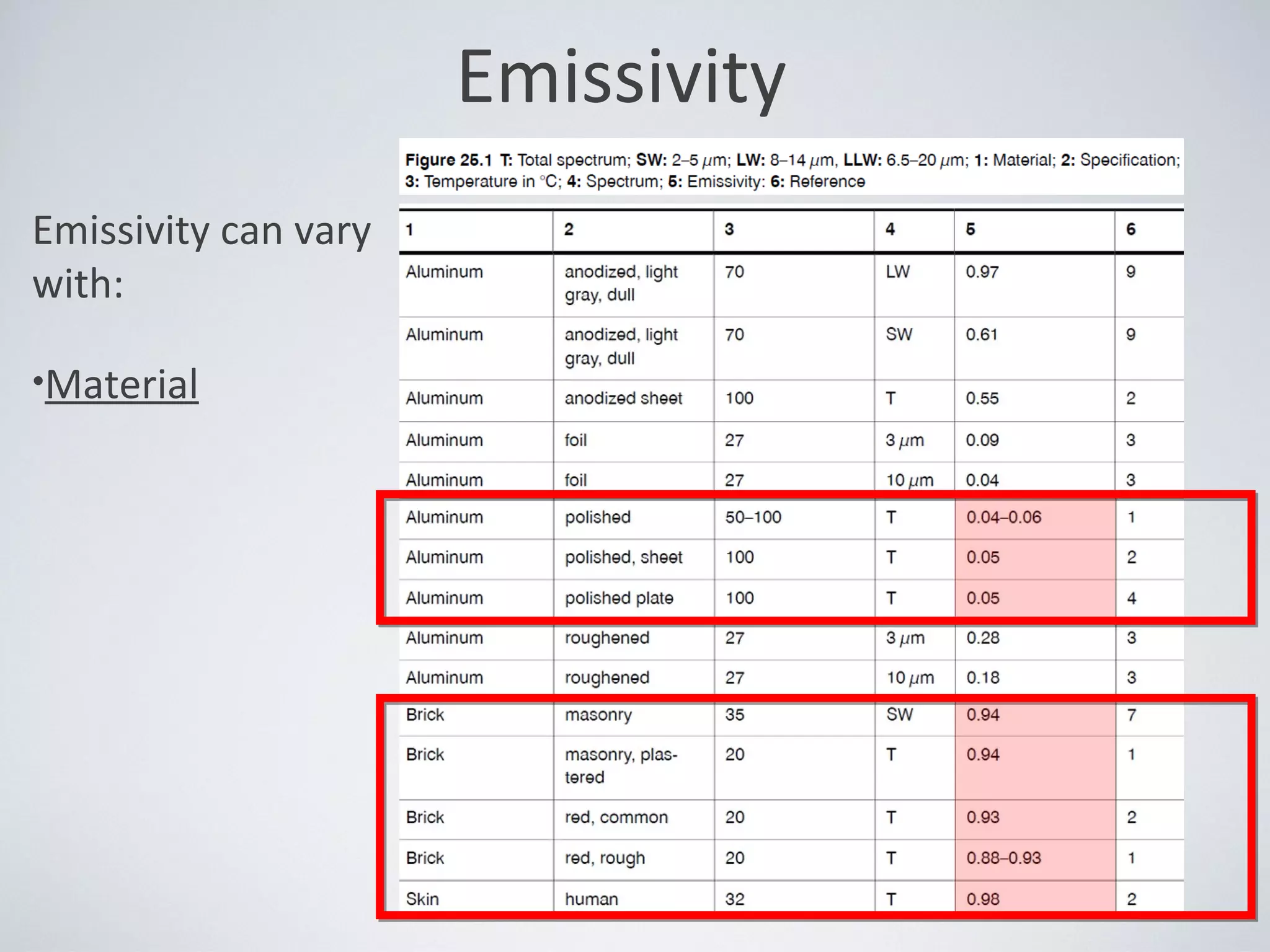
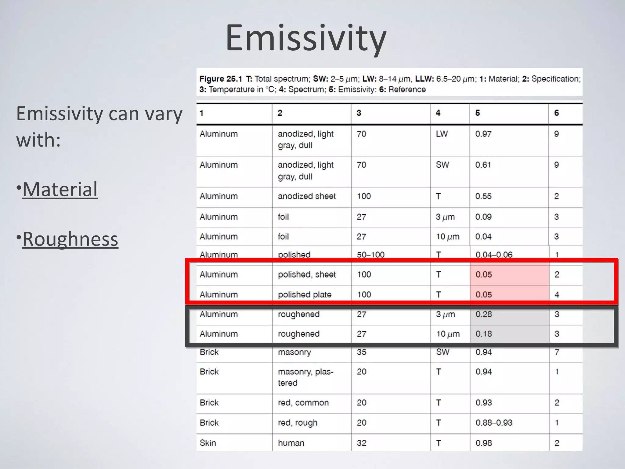
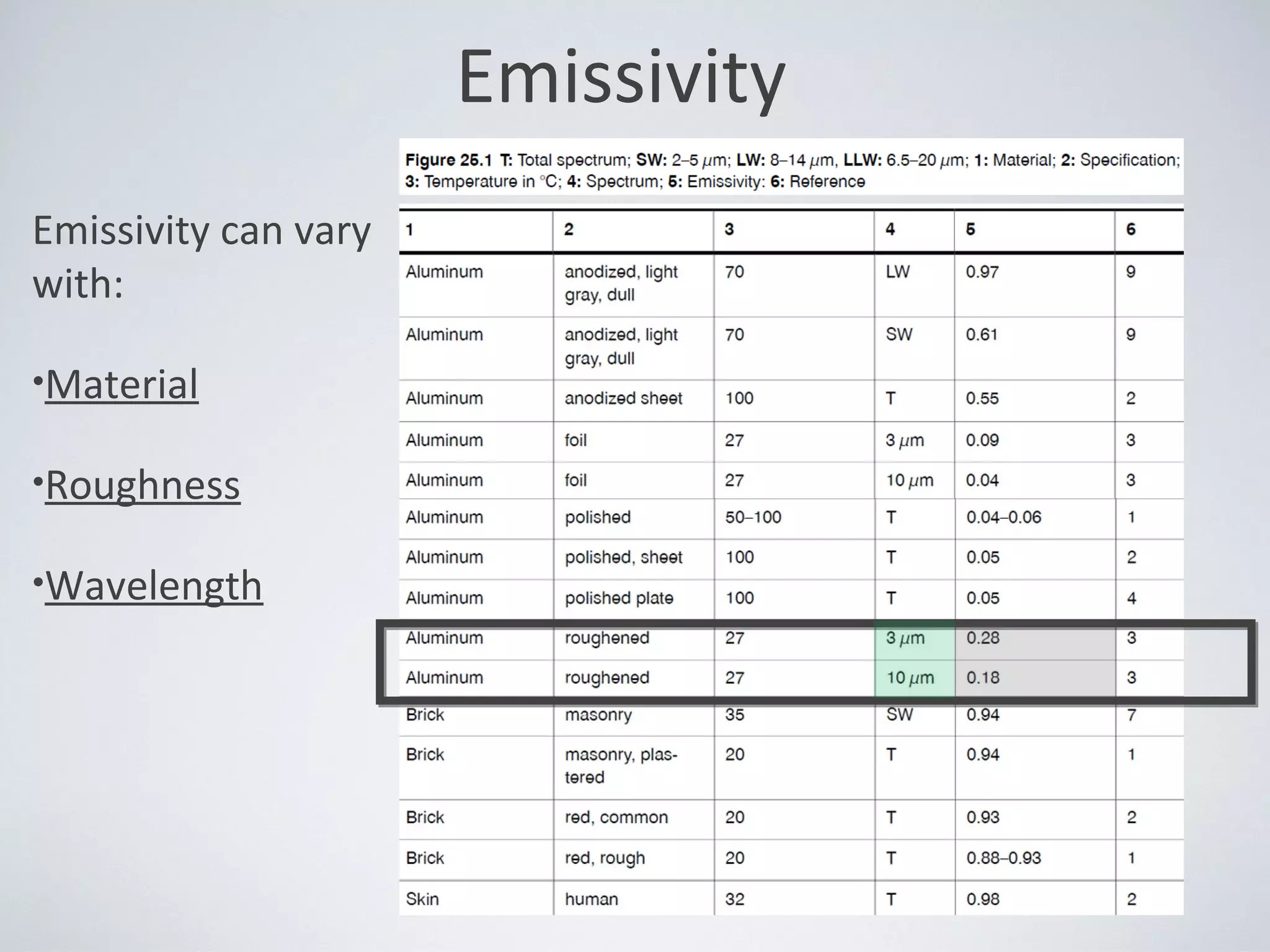
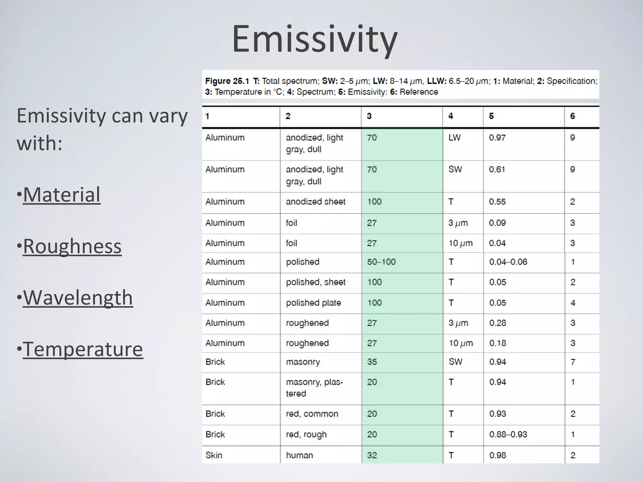
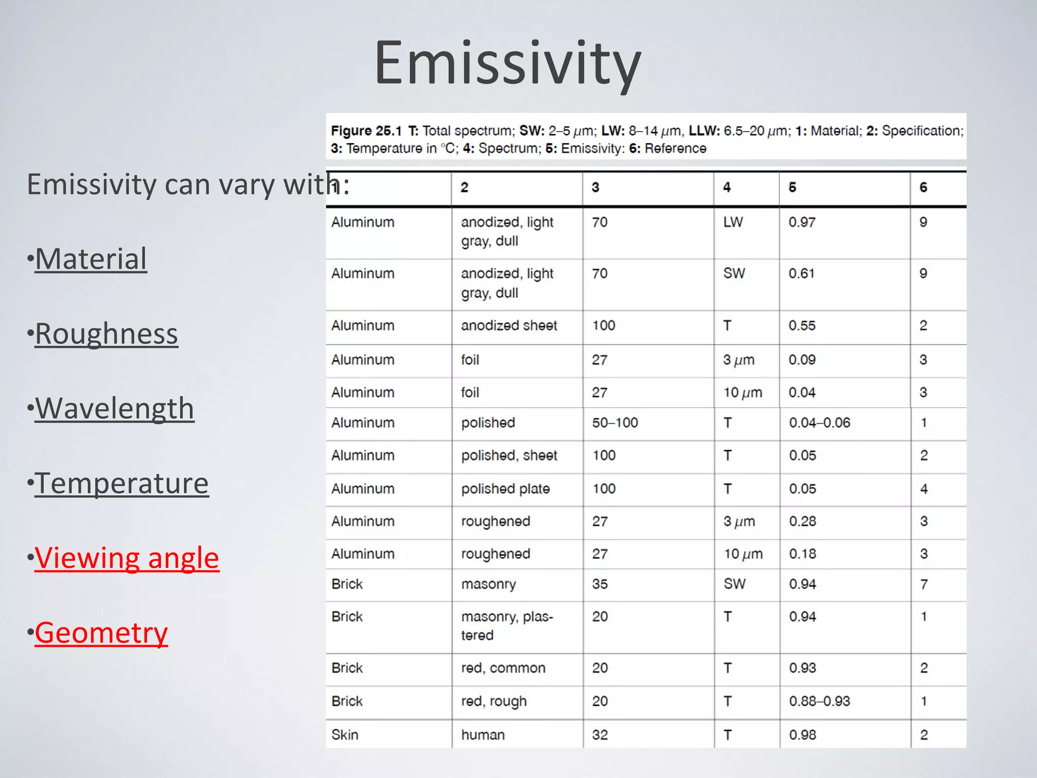
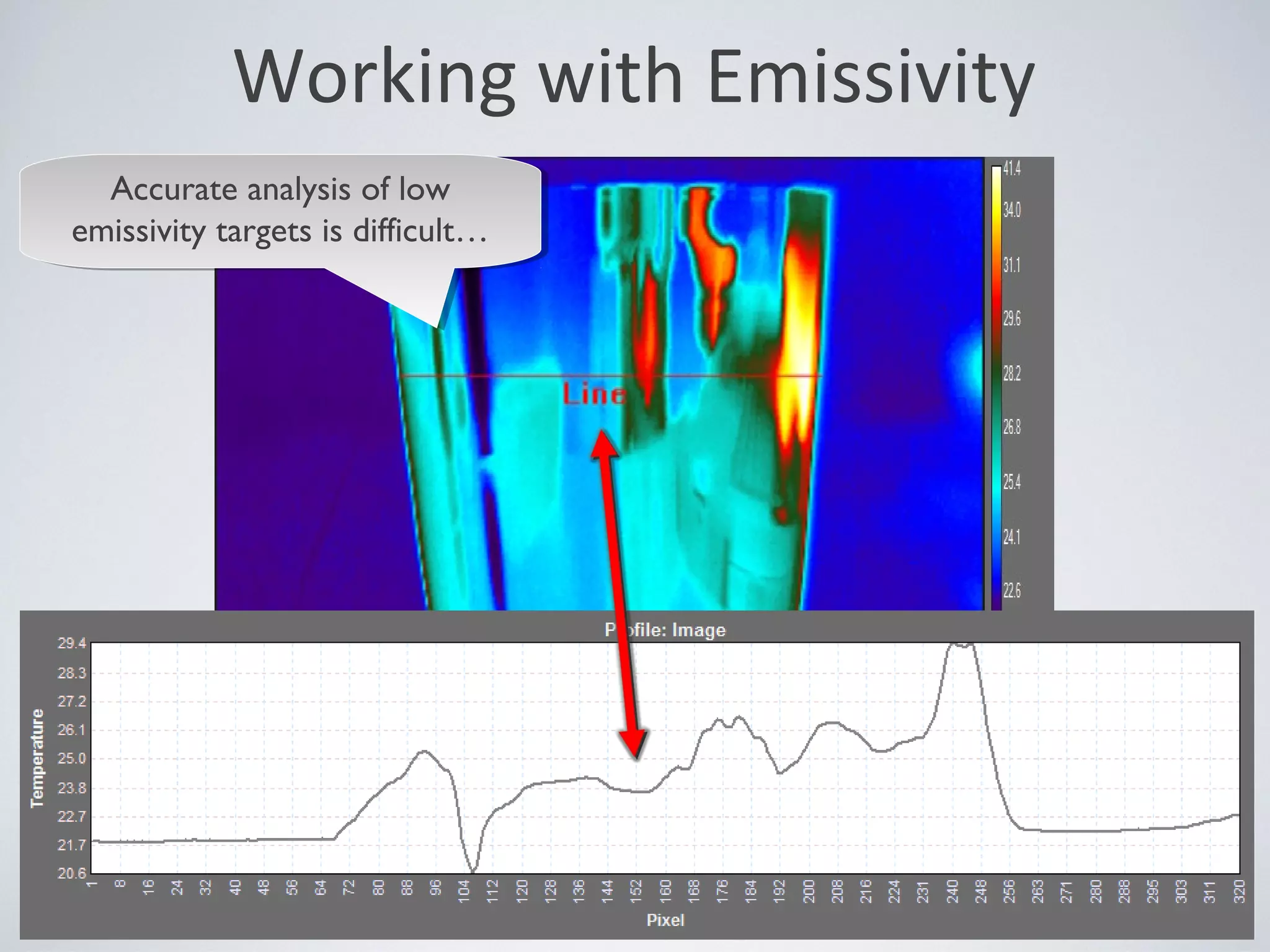
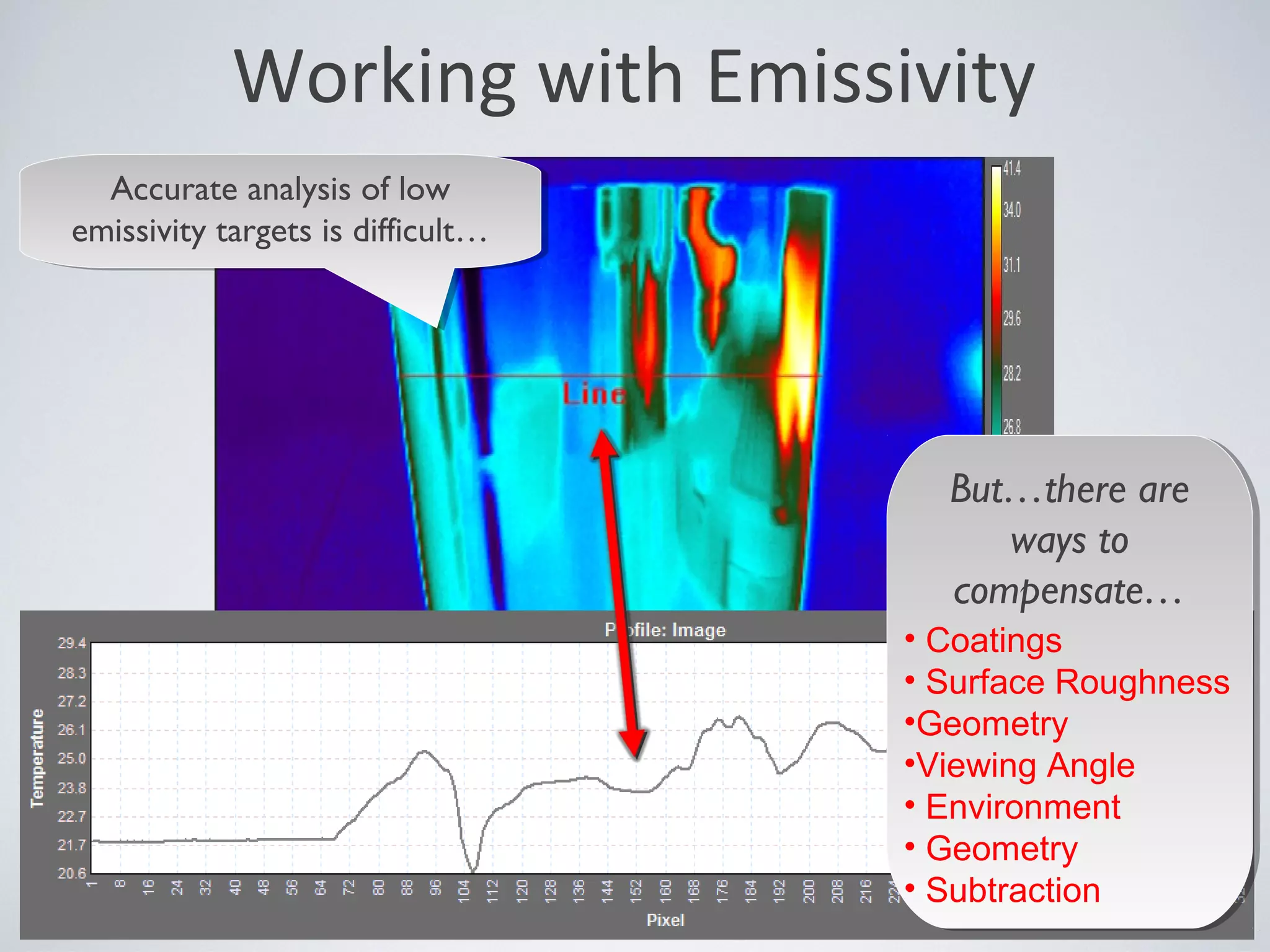
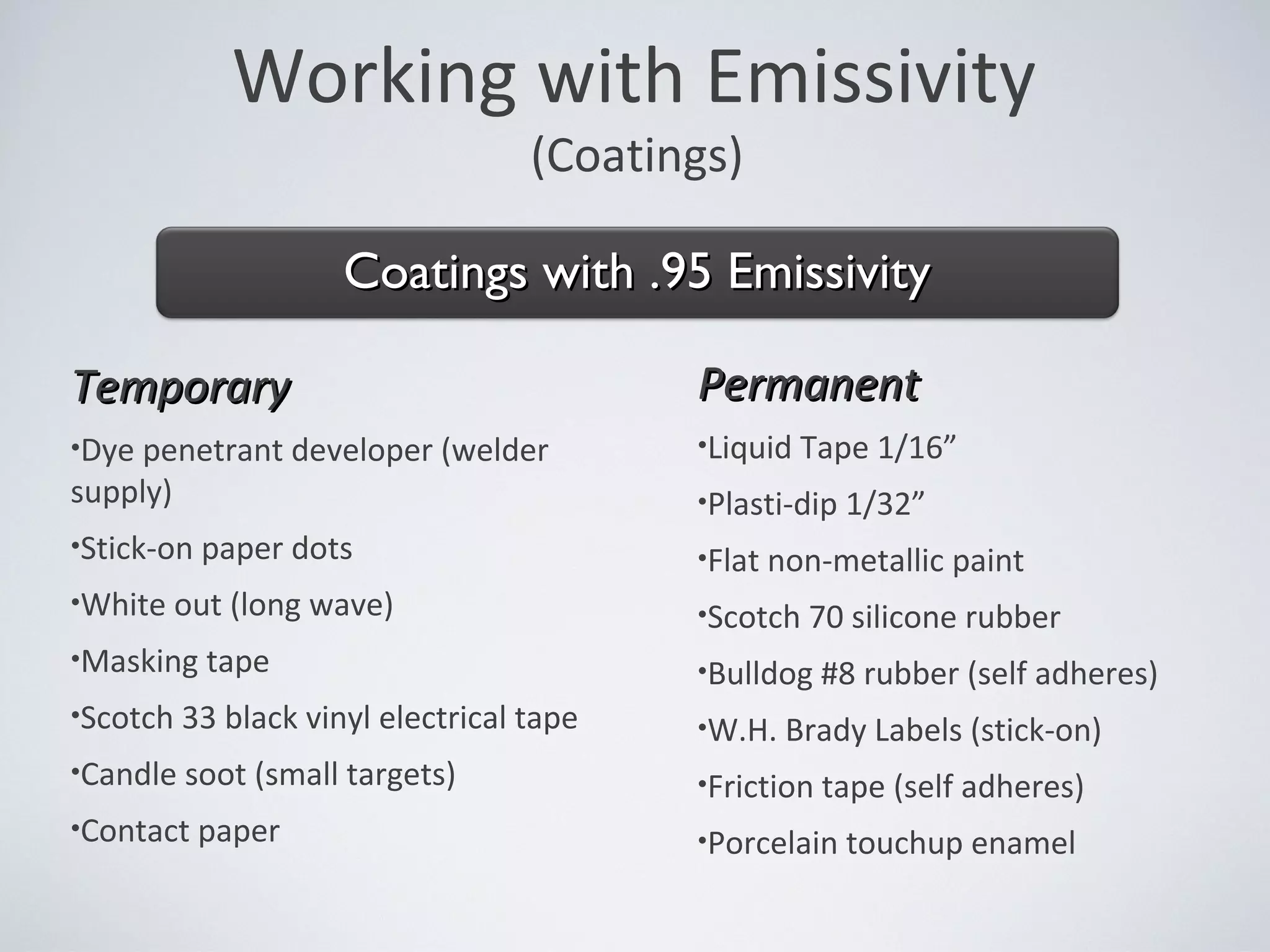
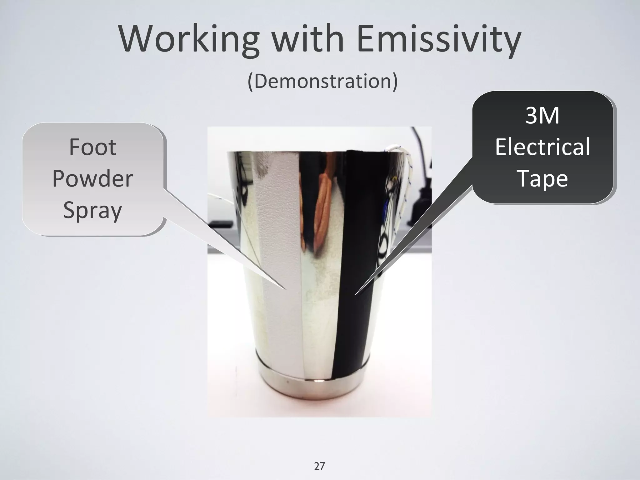
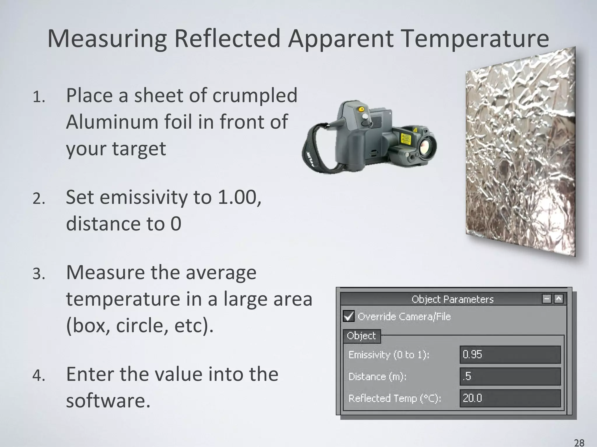
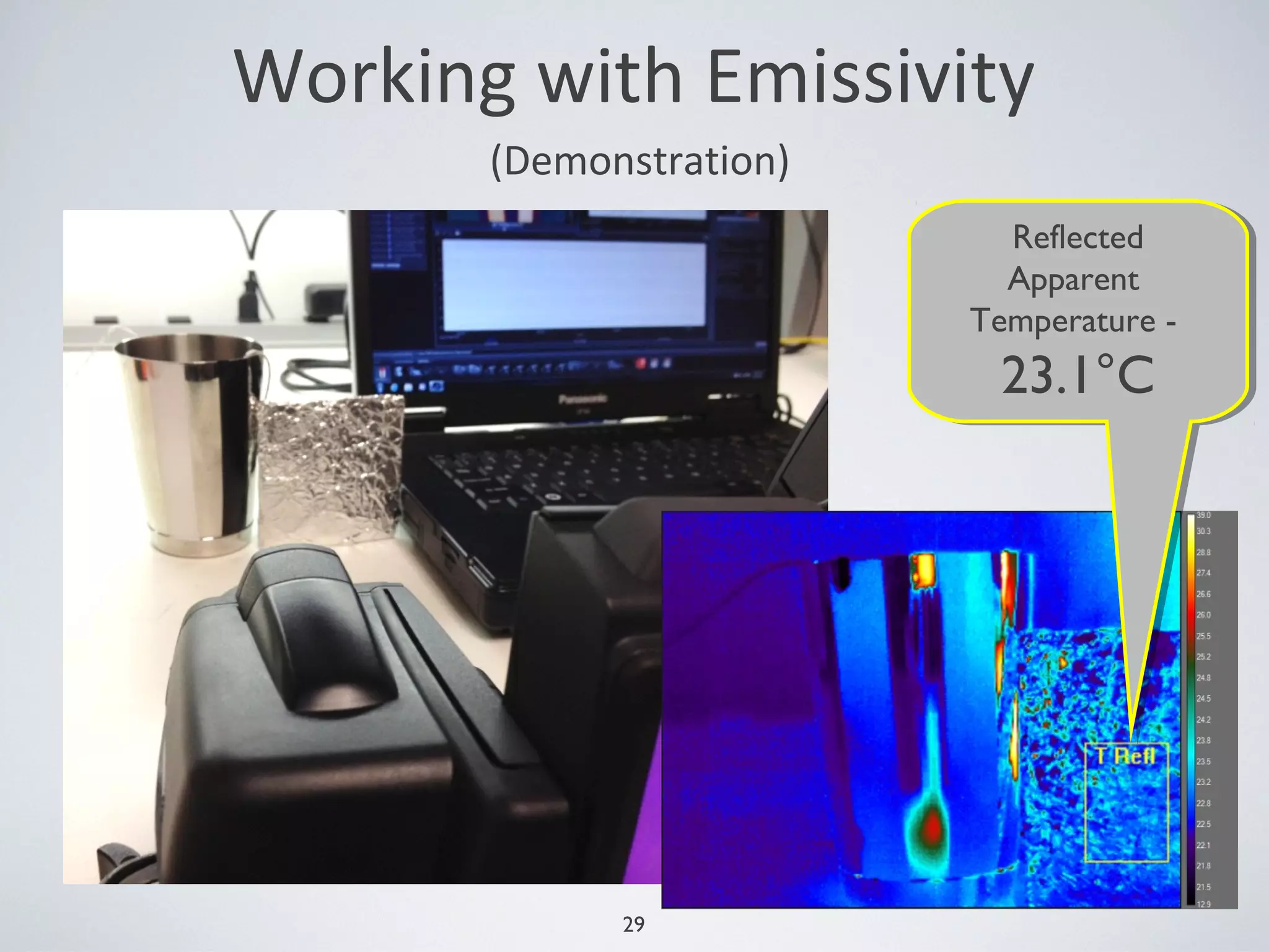
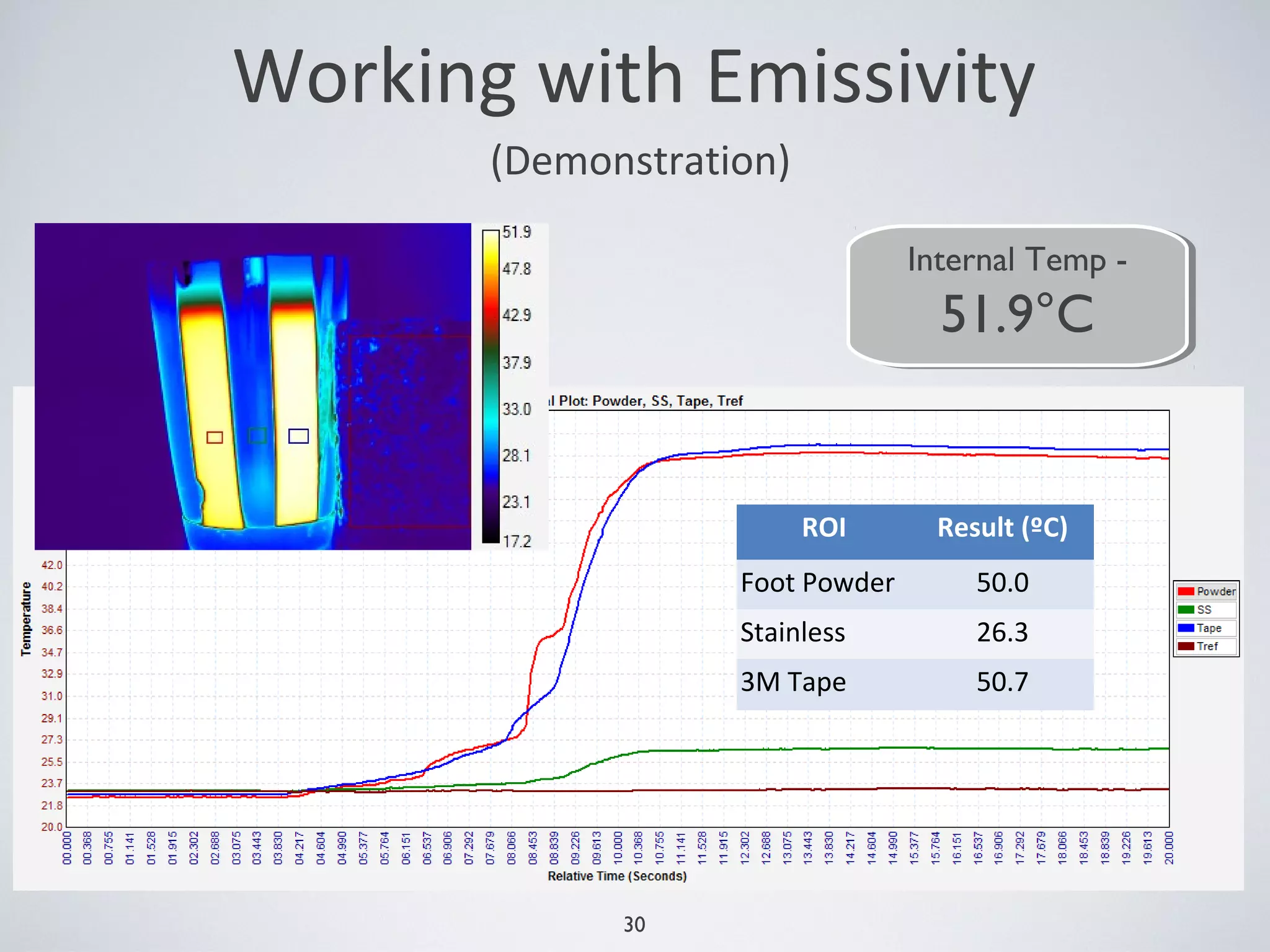
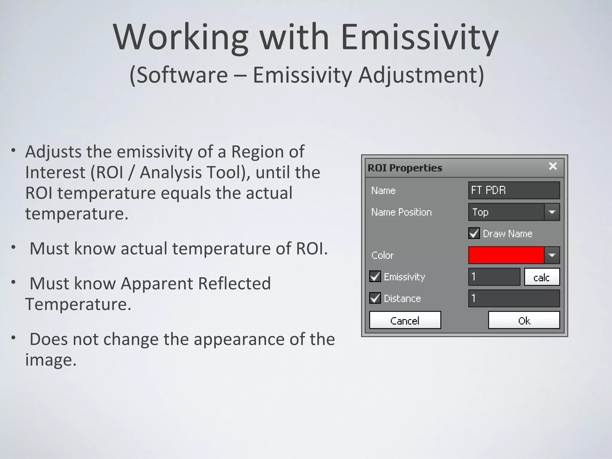
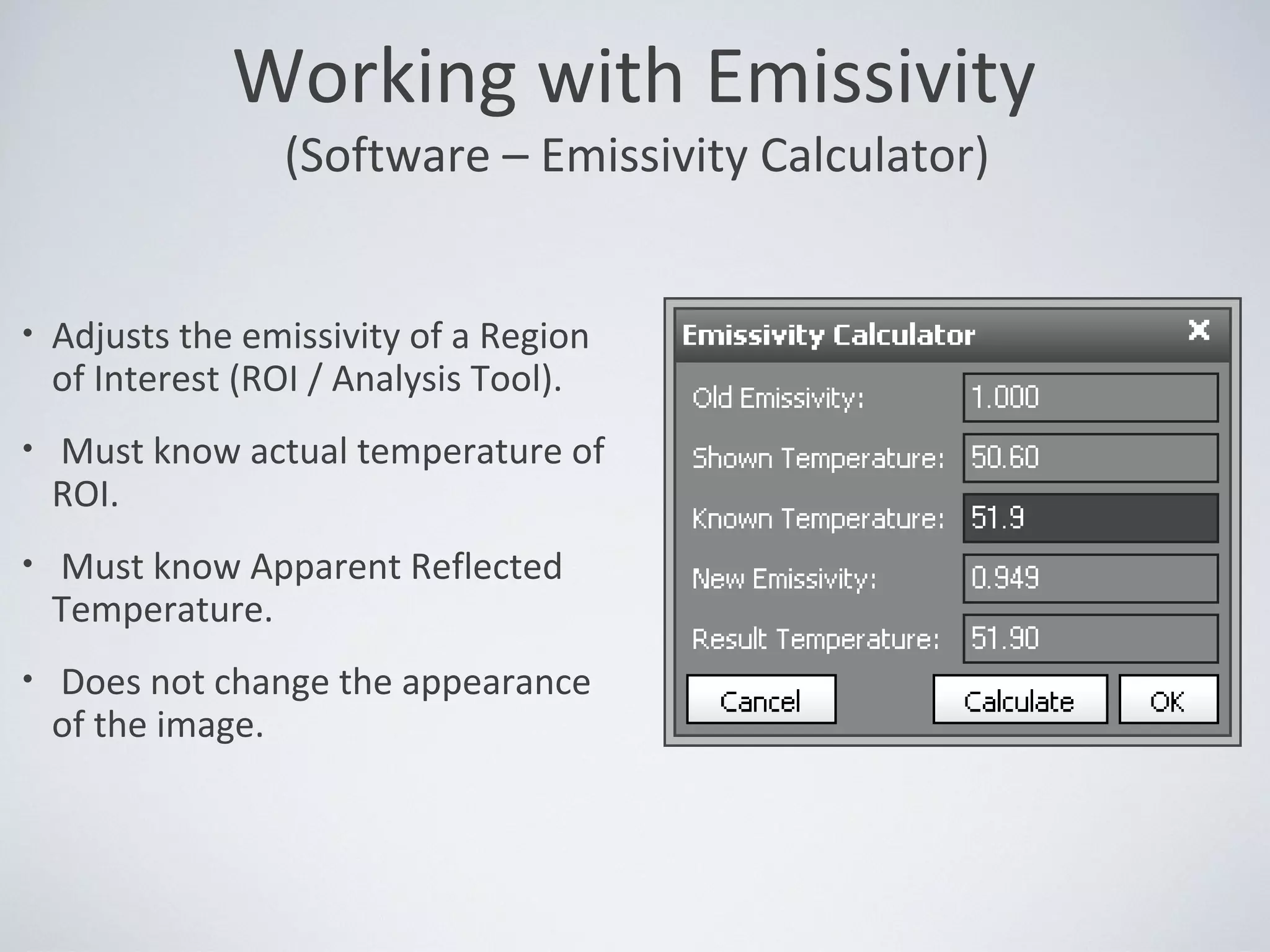
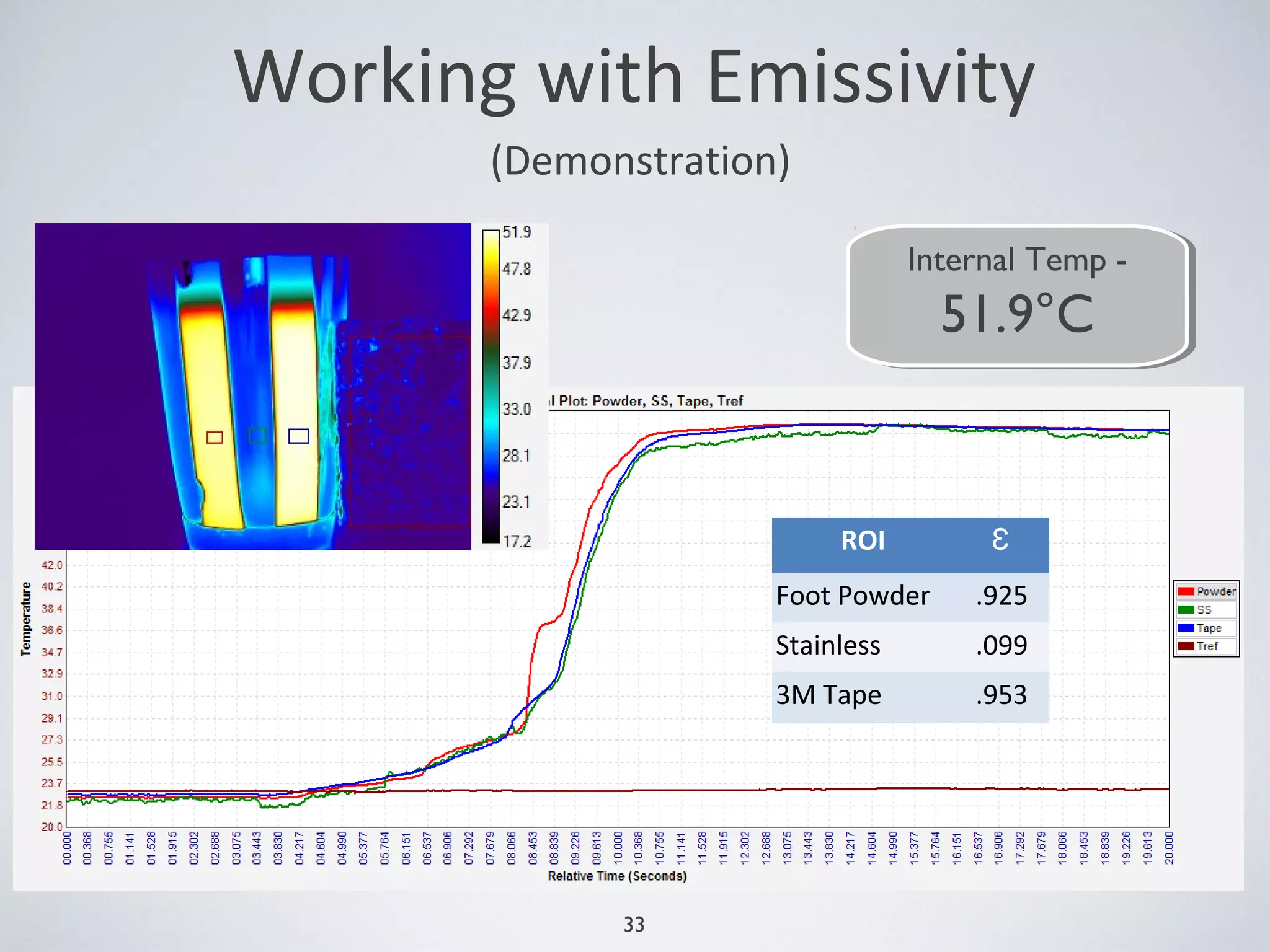
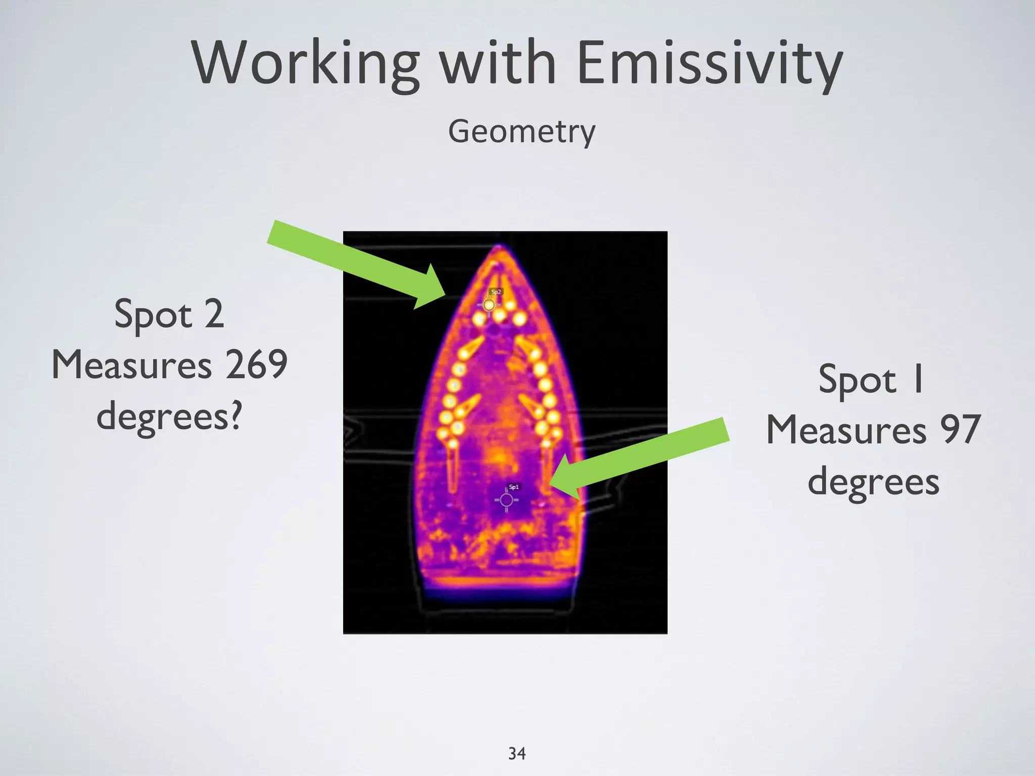
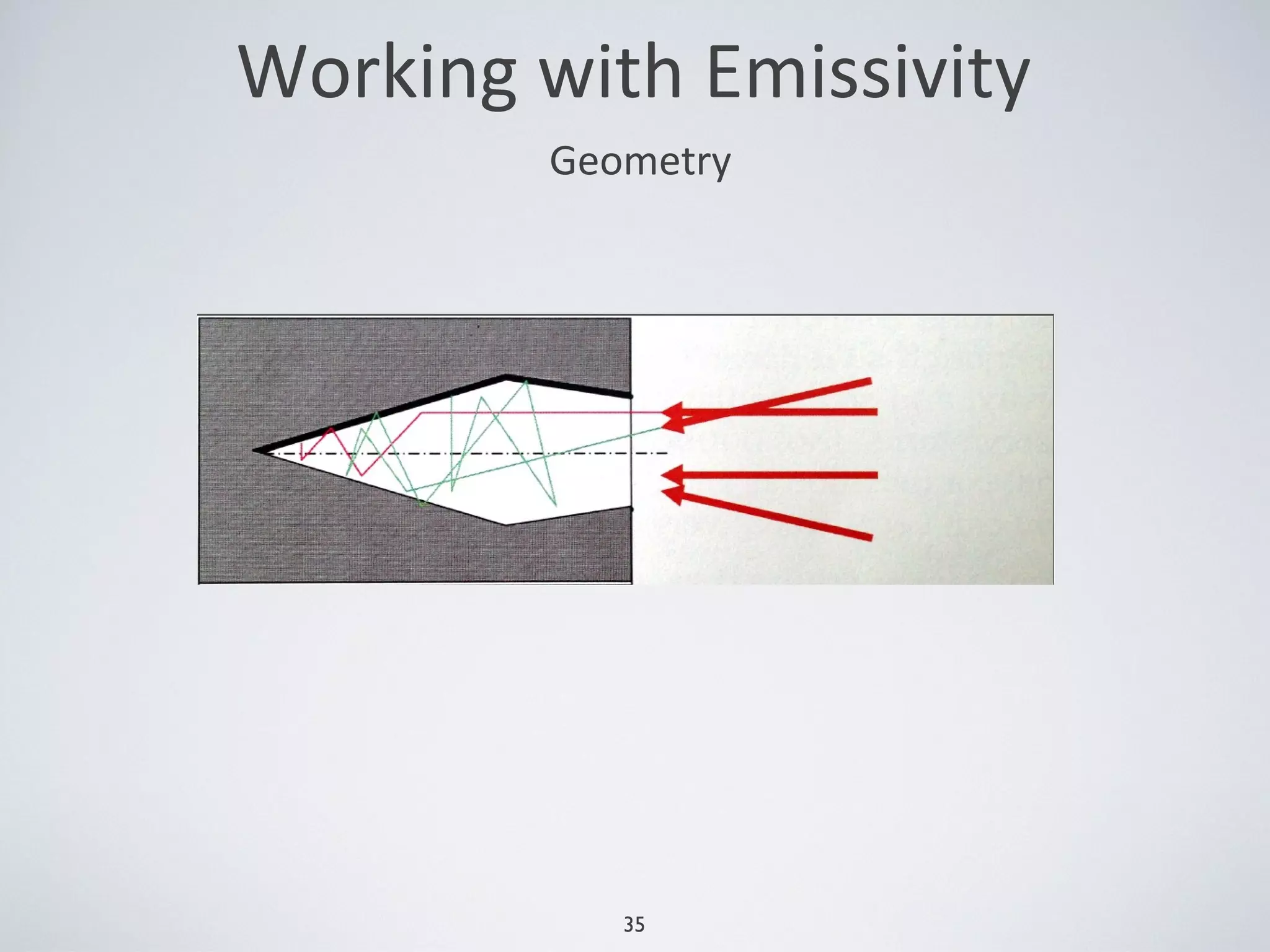
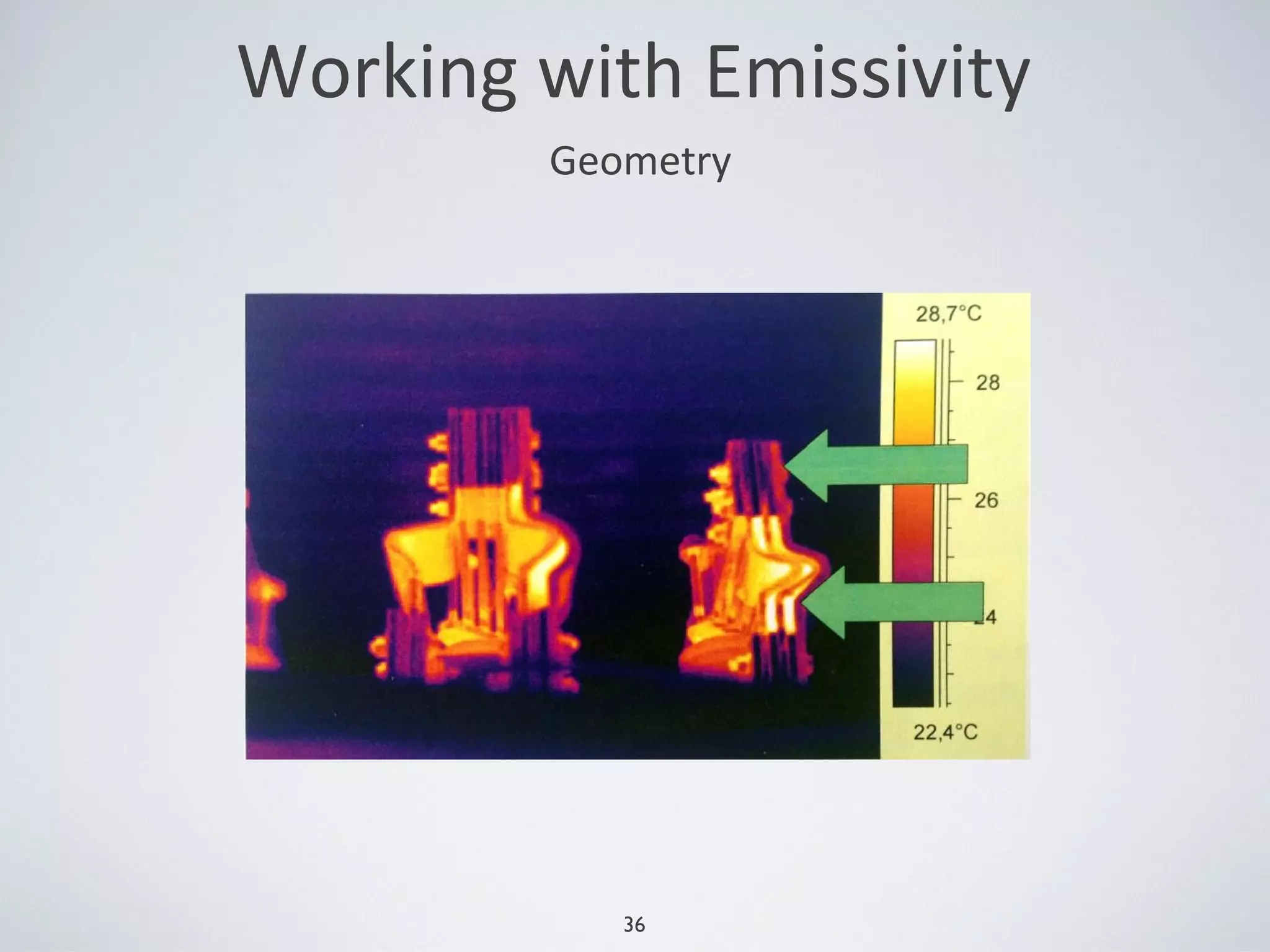
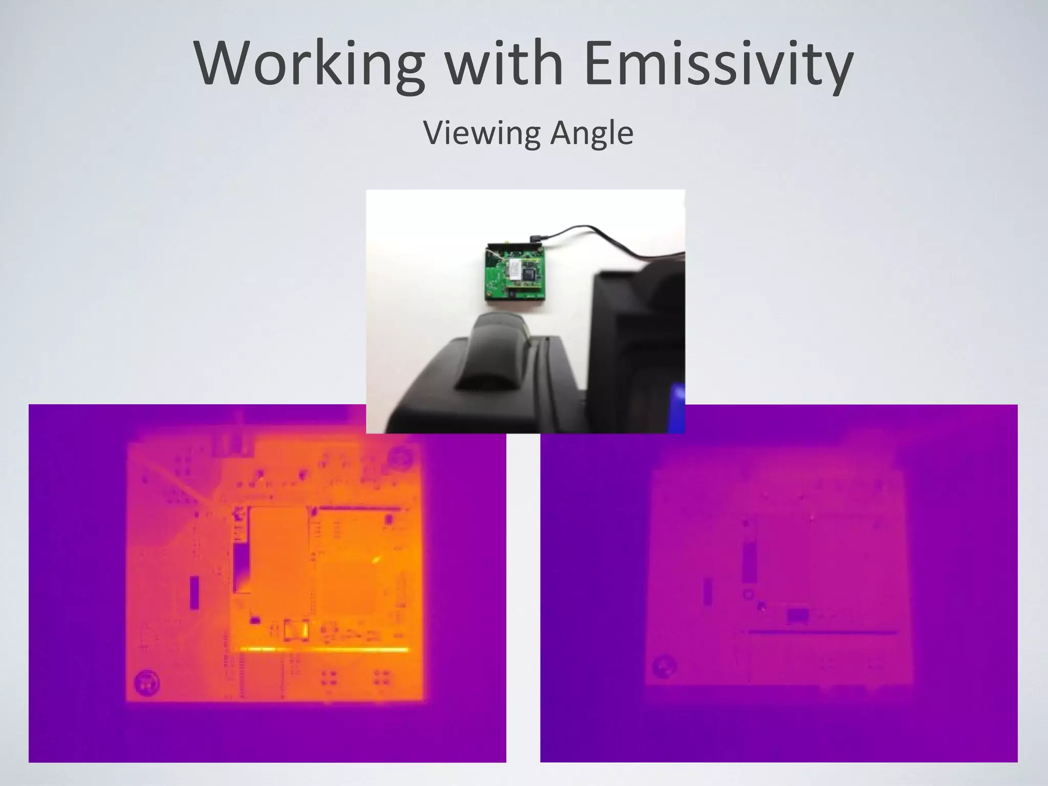
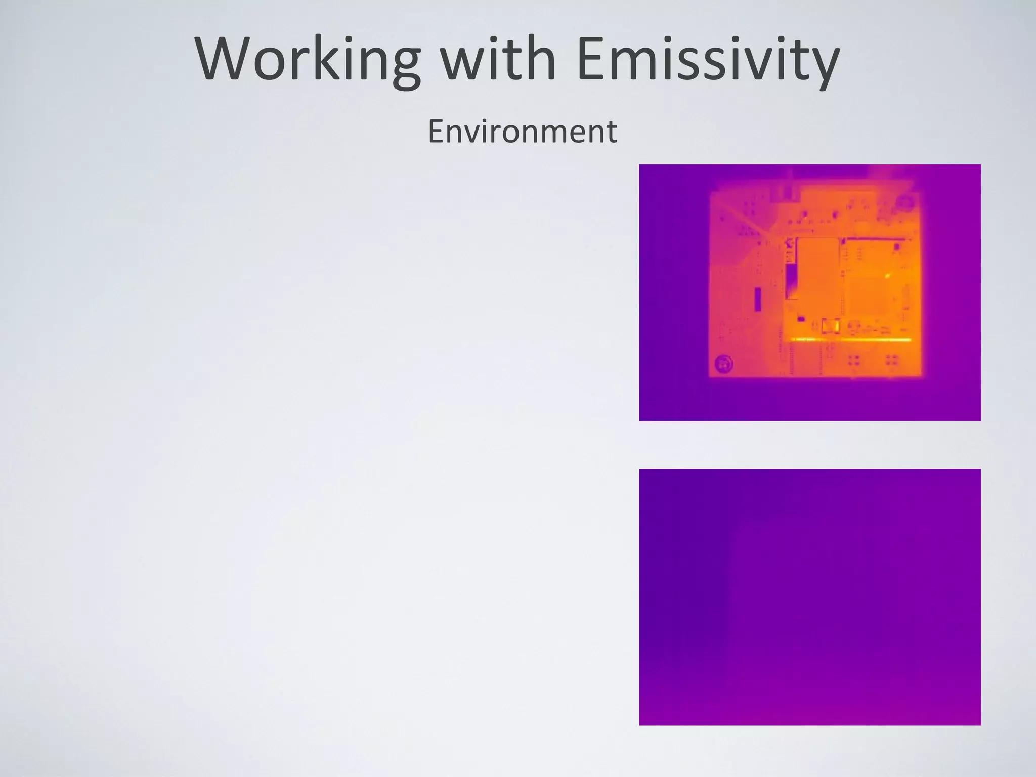
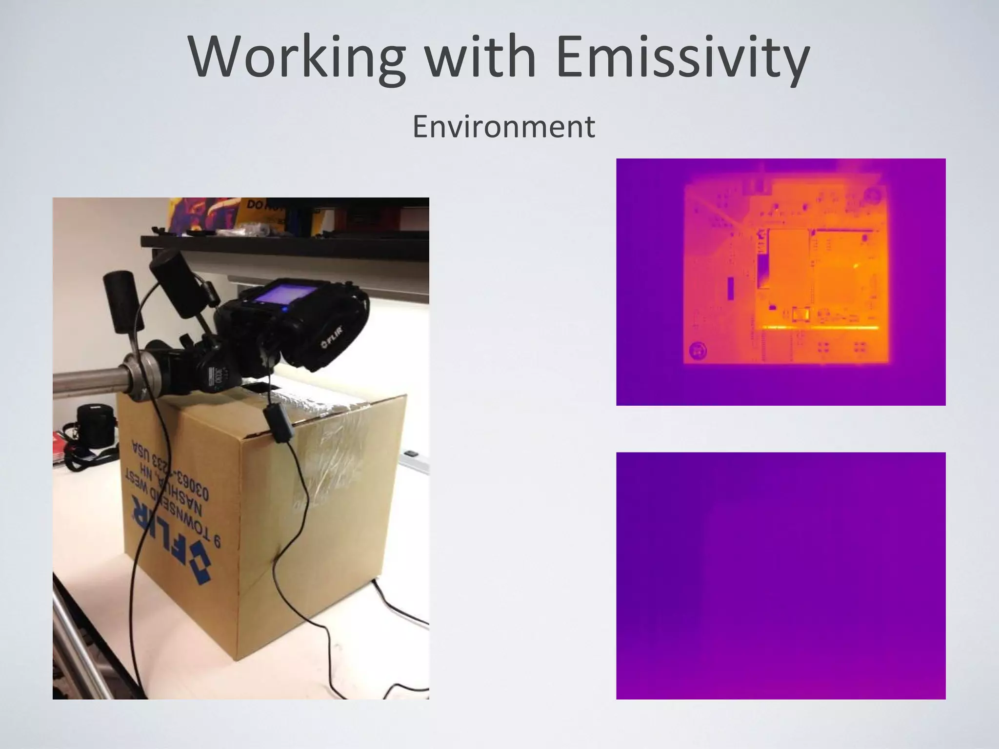
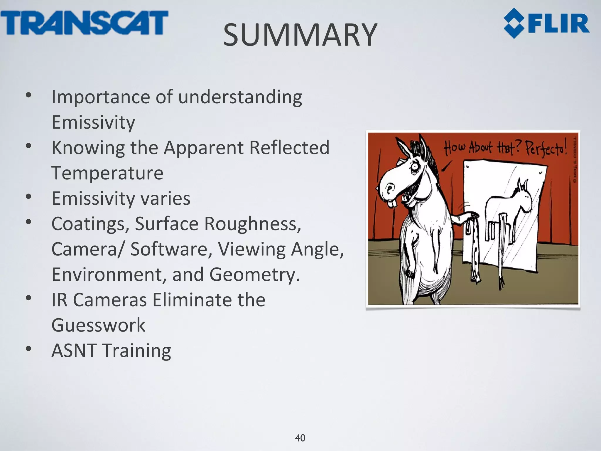
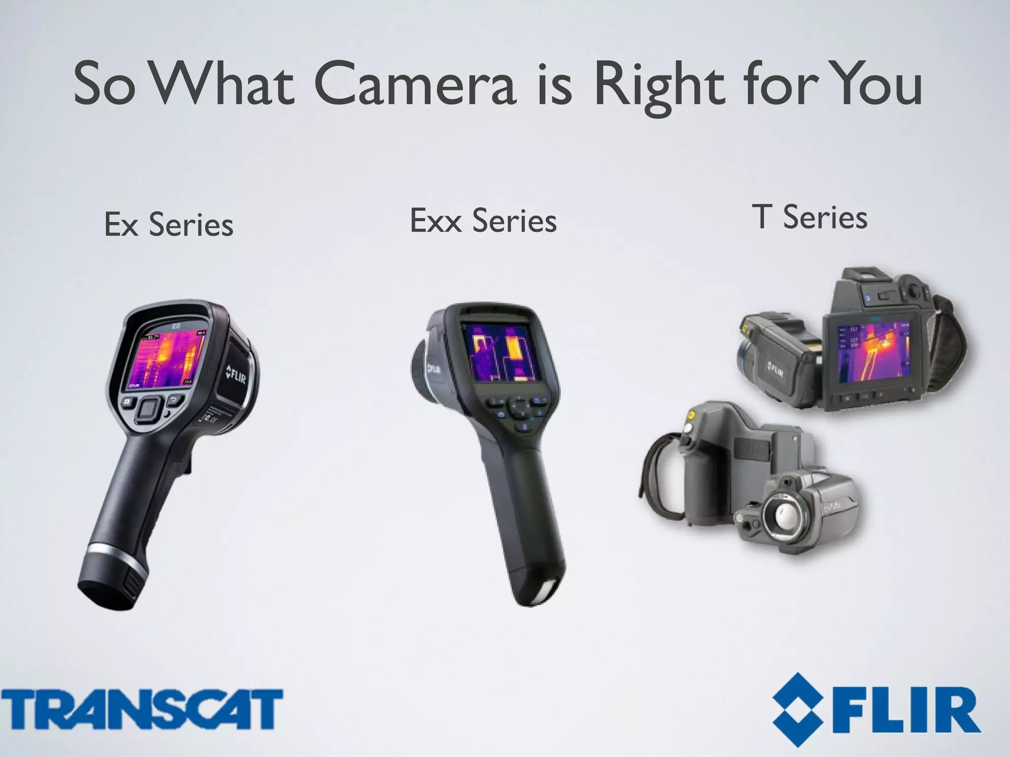
1
The Infrared AdvantageThe Infrared Advantage
Emissivity and the Potential Impacts
on your Thermal Measurement
2
• What does it mean to measure temperature?
• Infrared Theory Review
• Emissivity Discussion
• Working with Emissivity to make Measurements
• Summary
AGENDA
3
HOW YOU MEASURE TEMPERATURE...
All temperature measuring devices accomplish this
by measuring an effect of temperature:
•Thermistor: resistance changes with temperature
•Thermometer: volume changes with temperature
•Thermocouple: voltage changes with temperature
• IR Thermometers: voltage changes with temperature
• IR Camera: resistance changes with temperature
4
1. Camera sensor pixels are heated by the incoming IR radiation.
2. The pixel resistance changes when heated.
3. The pixel resistance is measured and calibrated to a temperature value.
4. Temperature values are presented as an IR image.
HOW INFRARED CAMERAS WORK
5
IR Cameras have several
thousand measurement spots.
A temperature measurement can
be made from any of those spots
in the IR image.
Like having up to 76,800Like having up to 76,800
IR Thermometers orIR Thermometers or
Thermocouples!Thermocouples!
INFRARED CAMERAS
6
•Thermal excitation of molecules causes collisions
•Collision energy is released as photons
•Occurs at temperatures above absolute zero
(-273.16⁰C, -459.72⁰F)
•Increases with temperature
•Heat transfer by the release of photons is known as
thermal radiation (electromagnetic radiation).
INFRARED THEORY REVIEW
7
•Longer wavelengths than visible radiation, shorter than radio
•Travels through space at the speed of light
•Can be focused, reflected, refracted
INFRARED THEORY REVIEW
8
The term “emissivity” is used to describe radiation efficiency
of a target compared to a blackbody at the same
wavelength, angle and temperature.
ɛ
Emissivity
9
= 1.0= 1.0
100% emission100% emission
ɛɛ
==
INFRARED THEORY REVIEW
ApparentApparent
TemperatureTemperature
ActualActual
TemperatureTemperature
10
Wabs
% transmission% transmission
INFRARED THEORY REVIEW
% emission% emission
% reflection% reflection
TOTAL
≠≠ ActualActual
TemperatureTemperature
< 1.0< 1.0ɛɛ
ReflectedReflected
ApparentApparent
TemperatureTemperature
ApparentApparent
TemperatureTemperature
11
WWabsabs
INFRARED THEORY REVIEW
25% reflection25% reflection
75% emission75% emission
ActualActual
TemperatureTemperature
ApparentApparent
TemperatureTemperature
ReflectedReflected
ApparentApparent
TemperatureTemperature
TOTALTOTAL
= 0.75= 0.75ɛɛ
≠≠
12
INFRARED THEORY REVIEW
25% reflection25% reflection
75% emission75% emission
ActualActual
TemperatureTemperature
40°C40°C
ApparentApparent
TemperatureTemperature
ReflectedReflected
ApparentApparent
TemperatureTemperature
0°C0°C
><><
TOTALTOTAL
= 0.75= 0.75ɛɛ
1313
INFRARED THEORY REVIEW
25% reflection25% reflection
75% emission75% emission
ActualActual
TemperatureTemperature
40°C40°C
ApparentApparent
TemperatureTemperature
ReflectedReflected
ApparentApparent
TemperatureTemperature
0°C0°C
<<
TOTALTOTAL
= 0.75= 0.75ɛɛ
1414
INFRARED THEORY REVIEW
25% reflection25% reflection
75% emission75% emission
ActualActual
TemperatureTemperature
40°C40°C
ApparentApparent
TemperatureTemperature
ReflectedReflected
ApparentApparent
TemperatureTemperature
500°C500°C
><><
TOTALTOTAL
= 0.75= 0.75ɛɛ
1515
INFRARED THEORY REVIEW
25% reflection25% reflection
75% emission75% emission
ActualActual
TemperatureTemperature
40°C40°C
ApparentApparent
TemperatureTemperature
ReflectedReflected
ApparentApparent
TemperatureTemperature
500°C500°C
>>
TOTALTOTAL
= 0.75= 0.75ɛɛ
Emissivity
Emissivity
Emissivity can vary
with:
•Material
Emissivity
Emissivity can vary
with:
•Material
•Roughness
Emissivity
Emissivity can vary
with:
•Material
•Roughness
•Wavelength
Emissivity
Emissivity can vary
with:
•Material
•Roughness
•Wavelength
•Temperature
Emissivity
Emissivity can vary with:
•Material
•Roughness
•Wavelength
•Temperature
•Viewing angle
•Geometry
22
MEASUREMENT DEMONSTRATION
23
DEMONSTRATION
• FLIR T420
•Type K Thermocouple
• Stainless Steel Cup
• Scotch 3M Electrical Tape
• Foot Powder Spray
Accurate analysis of low
emissivity targets is difficult…
Accurate analysis of low
emissivity targets is difficult…
Working with Emissivity
Accurate analysis of low
emissivity targets is difficult…
Accurate analysis of low
emissivity targets is difficult…
But…there are
ways to
compensate…
But…there are
ways to
compensate…
• Coatings
• Surface Roughness
•Geometry
•Viewing Angle
• Environment
• Geometry
• Subtraction
Working with Emissivity
(Coatings)
TemporaryTemporary
•Dye penetrant developer (welder
supply)
•Stick-on paper dots
•White out (long wave)
•Masking tape
•Scotch 33 black vinyl electrical tape
•Candle soot (small targets)
•Contact paper
PermanentPermanent
•Liquid Tape 1/16”
•Plasti-dip 1/32”
•Flat non-metallic paint
•Scotch 70 silicone rubber
•Bulldog #8 rubber (self adheres)
•W.H. Brady Labels (stick-on)
•Friction tape (self adheres)
•Porcelain touchup enamel
Coatings with .95 EmissivityCoatings with .95 Emissivity
27
(Demonstration)
Foot
Powder
Spray
Foot
Powder
Spray
3M
Electrical
Tape
3M
Electrical
Tape
Working with Emissivity
Measuring Reflected Apparent Temperature
1. Place a sheet of crumpled
Aluminum foil in front of
your target
2. Set emissivity to 1.00,
distance to 0
3. Measure the average
temperature in a large area
(box, circle, etc).
4. Enter the value into the
software.
28
29
Reflected
Apparent
Temperature -
23.1°C
Reflected
Apparent
Temperature -
23.1°C
(Demonstration)
Working with Emissivity
30
(Demonstration)
Working with Emissivity
Internal Temp -
51.9°C
Internal Temp -
51.9°C
ROI Result (ºC)
Foot Powder 50.0
Stainless 26.3
3M Tape 50.7
• Adjusts the emissivity of a Region of
Interest (ROI / Analysis Tool), until the
ROI temperature equals the actual
temperature.
• Must know actual temperature of ROI.
• Must know Apparent Reflected
Temperature.
• Does not change the appearance of the
image.
Working with Emissivity
(Software – Emissivity Adjustment)
• Adjusts the emissivity of a Region
of Interest (ROI / Analysis Tool).
• Must know actual temperature of
ROI.
• Must know Apparent Reflected
Temperature.
• Does not change the appearance
of the image.
Working with Emissivity
(Software – Emissivity Calculator)
33
(Demonstration)
Working with Emissivity
Internal Temp -
51.9°C
Internal Temp -
51.9°C
ROI Ɛ
Foot Powder .925
Stainless .099
3M Tape .953
34
Spot 1
Measures 97
degrees
Spot 2
Measures 269
degrees?
Working with Emissivity
Geometry
35
Working with Emissivity
Geometry
36
Working with Emissivity
Geometry
Working with Emissivity
Viewing Angle
Working with Emissivity
Environment
Working with Emissivity
Environment
40
SUMMARY
• Importance of understanding
Emissivity
• Knowing the Apparent Reflected
Temperature
• Emissivity varies
• Coatings, Surface Roughness,
Camera/ Software, Viewing Angle,
Environment, and Geometry.
• IR Cameras Eliminate the
Guesswork
• ASNT Training
So What Camera is Right forYou
Ex Series T SeriesExx Series
Questions you Should Ask
• How far from the target?
• How hot is the target?
• What other applications?
• How often will you use the camera?
• What camera features do I need?
• Who will use the camera or cameras?
• What type of reporting and trending will I do?
• Radiometric JPEG image storage
• MSX Technology
• Fixed Focus (focus free)
• 3” Color LCD
• -20° C to 250° C Temperature Range
• Cost $995 to $5,995
FLIR Ex Series – Spot Gun
Replacement
FLIR Exx-Series- Performance Cameras
• Large Touch screen
• Wi-Fi and Bluetooth for remote reporting
• MSX Technology
• Laser, video light
• Accessory Lenses, wide angle, telephoto
• Temp ranges up to 650° C
• Cost $3,995 to $7,995
FLIR T Series- High Performance
• Ergonomics/Outdoor Applications
• High Temperature, up to 2,000° C
• High Resolution up to (640 x 480)
• Remote Controls
• $8,750 to $26,950
46
Thanks

Emissivity_Webinar_FLIR_Transcat_03252014

  • 1.
    1 The Infrared AdvantageTheInfrared Advantage Emissivity and the Potential Impacts on your Thermal Measurement
  • 2.
    2 • What doesit mean to measure temperature? • Infrared Theory Review • Emissivity Discussion • Working with Emissivity to make Measurements • Summary AGENDA
  • 3.
    3 HOW YOU MEASURETEMPERATURE... All temperature measuring devices accomplish this by measuring an effect of temperature: •Thermistor: resistance changes with temperature •Thermometer: volume changes with temperature •Thermocouple: voltage changes with temperature • IR Thermometers: voltage changes with temperature • IR Camera: resistance changes with temperature
  • 4.
    4 1. Camera sensorpixels are heated by the incoming IR radiation. 2. The pixel resistance changes when heated. 3. The pixel resistance is measured and calibrated to a temperature value. 4. Temperature values are presented as an IR image. HOW INFRARED CAMERAS WORK
  • 5.
    5 IR Cameras haveseveral thousand measurement spots. A temperature measurement can be made from any of those spots in the IR image. Like having up to 76,800Like having up to 76,800 IR Thermometers orIR Thermometers or Thermocouples!Thermocouples! INFRARED CAMERAS
  • 6.
    6 •Thermal excitation ofmolecules causes collisions •Collision energy is released as photons •Occurs at temperatures above absolute zero (-273.16⁰C, -459.72⁰F) •Increases with temperature •Heat transfer by the release of photons is known as thermal radiation (electromagnetic radiation). INFRARED THEORY REVIEW
  • 7.
    7 •Longer wavelengths thanvisible radiation, shorter than radio •Travels through space at the speed of light •Can be focused, reflected, refracted INFRARED THEORY REVIEW
  • 8.
    8 The term “emissivity”is used to describe radiation efficiency of a target compared to a blackbody at the same wavelength, angle and temperature. ɛ Emissivity
  • 9.
    9 = 1.0= 1.0 100%emission100% emission ɛɛ == INFRARED THEORY REVIEW ApparentApparent TemperatureTemperature ActualActual TemperatureTemperature
  • 10.
    10 Wabs % transmission% transmission INFRAREDTHEORY REVIEW % emission% emission % reflection% reflection TOTAL ≠≠ ActualActual TemperatureTemperature < 1.0< 1.0ɛɛ ReflectedReflected ApparentApparent TemperatureTemperature ApparentApparent TemperatureTemperature
  • 11.
    11 WWabsabs INFRARED THEORY REVIEW 25%reflection25% reflection 75% emission75% emission ActualActual TemperatureTemperature ApparentApparent TemperatureTemperature ReflectedReflected ApparentApparent TemperatureTemperature TOTALTOTAL = 0.75= 0.75ɛɛ ≠≠
  • 12.
    12 INFRARED THEORY REVIEW 25%reflection25% reflection 75% emission75% emission ActualActual TemperatureTemperature 40°C40°C ApparentApparent TemperatureTemperature ReflectedReflected ApparentApparent TemperatureTemperature 0°C0°C ><>< TOTALTOTAL = 0.75= 0.75ɛɛ
  • 13.
    1313 INFRARED THEORY REVIEW 25%reflection25% reflection 75% emission75% emission ActualActual TemperatureTemperature 40°C40°C ApparentApparent TemperatureTemperature ReflectedReflected ApparentApparent TemperatureTemperature 0°C0°C << TOTALTOTAL = 0.75= 0.75ɛɛ
  • 14.
    1414 INFRARED THEORY REVIEW 25%reflection25% reflection 75% emission75% emission ActualActual TemperatureTemperature 40°C40°C ApparentApparent TemperatureTemperature ReflectedReflected ApparentApparent TemperatureTemperature 500°C500°C ><>< TOTALTOTAL = 0.75= 0.75ɛɛ
  • 15.
    1515 INFRARED THEORY REVIEW 25%reflection25% reflection 75% emission75% emission ActualActual TemperatureTemperature 40°C40°C ApparentApparent TemperatureTemperature ReflectedReflected ApparentApparent TemperatureTemperature 500°C500°C >> TOTALTOTAL = 0.75= 0.75ɛɛ
  • 16.
  • 17.
  • 18.
  • 19.
  • 20.
  • 21.
    Emissivity Emissivity can varywith: •Material •Roughness •Wavelength •Temperature •Viewing angle •Geometry
  • 22.
  • 23.
    23 DEMONSTRATION • FLIR T420 •TypeK Thermocouple • Stainless Steel Cup • Scotch 3M Electrical Tape • Foot Powder Spray
  • 24.
    Accurate analysis oflow emissivity targets is difficult… Accurate analysis of low emissivity targets is difficult… Working with Emissivity
  • 25.
    Accurate analysis oflow emissivity targets is difficult… Accurate analysis of low emissivity targets is difficult… But…there are ways to compensate… But…there are ways to compensate… • Coatings • Surface Roughness •Geometry •Viewing Angle • Environment • Geometry • Subtraction Working with Emissivity
  • 26.
    Working with Emissivity (Coatings) TemporaryTemporary •Dyepenetrant developer (welder supply) •Stick-on paper dots •White out (long wave) •Masking tape •Scotch 33 black vinyl electrical tape •Candle soot (small targets) •Contact paper PermanentPermanent •Liquid Tape 1/16” •Plasti-dip 1/32” •Flat non-metallic paint •Scotch 70 silicone rubber •Bulldog #8 rubber (self adheres) •W.H. Brady Labels (stick-on) •Friction tape (self adheres) •Porcelain touchup enamel Coatings with .95 EmissivityCoatings with .95 Emissivity
  • 27.
  • 28.
    Measuring Reflected ApparentTemperature 1. Place a sheet of crumpled Aluminum foil in front of your target 2. Set emissivity to 1.00, distance to 0 3. Measure the average temperature in a large area (box, circle, etc). 4. Enter the value into the software. 28
  • 29.
  • 30.
    30 (Demonstration) Working with Emissivity InternalTemp - 51.9°C Internal Temp - 51.9°C ROI Result (ºC) Foot Powder 50.0 Stainless 26.3 3M Tape 50.7
  • 31.
    • Adjusts theemissivity of a Region of Interest (ROI / Analysis Tool), until the ROI temperature equals the actual temperature. • Must know actual temperature of ROI. • Must know Apparent Reflected Temperature. • Does not change the appearance of the image. Working with Emissivity (Software – Emissivity Adjustment)
  • 32.
    • Adjusts theemissivity of a Region of Interest (ROI / Analysis Tool). • Must know actual temperature of ROI. • Must know Apparent Reflected Temperature. • Does not change the appearance of the image. Working with Emissivity (Software – Emissivity Calculator)
  • 33.
    33 (Demonstration) Working with Emissivity InternalTemp - 51.9°C Internal Temp - 51.9°C ROI Ɛ Foot Powder .925 Stainless .099 3M Tape .953
  • 34.
    34 Spot 1 Measures 97 degrees Spot2 Measures 269 degrees? Working with Emissivity Geometry
  • 35.
  • 36.
  • 37.
  • 38.
  • 39.
  • 40.
    40 SUMMARY • Importance ofunderstanding Emissivity • Knowing the Apparent Reflected Temperature • Emissivity varies • Coatings, Surface Roughness, Camera/ Software, Viewing Angle, Environment, and Geometry. • IR Cameras Eliminate the Guesswork • ASNT Training
  • 41.
    So What Camerais Right forYou Ex Series T SeriesExx Series
  • 42.
    Questions you ShouldAsk • How far from the target? • How hot is the target? • What other applications? • How often will you use the camera? • What camera features do I need? • Who will use the camera or cameras? • What type of reporting and trending will I do?
  • 43.
    • Radiometric JPEGimage storage • MSX Technology • Fixed Focus (focus free) • 3” Color LCD • -20° C to 250° C Temperature Range • Cost $995 to $5,995 FLIR Ex Series – Spot Gun Replacement
  • 44.
    FLIR Exx-Series- PerformanceCameras • Large Touch screen • Wi-Fi and Bluetooth for remote reporting • MSX Technology • Laser, video light • Accessory Lenses, wide angle, telephoto • Temp ranges up to 650° C • Cost $3,995 to $7,995
  • 45.
    FLIR T Series-High Performance • Ergonomics/Outdoor Applications • High Temperature, up to 2,000° C • High Resolution up to (640 x 480) • Remote Controls • $8,750 to $26,950
  • 46.

Editor's Notes

  • #2 Good day and welcome. It is my pleasure to present this webinar on behalf of TransCat and FLIR Systems. We appreciate you taking time out of your schedules to meet with us for the next 30-40 minutes discussing Emissivity and the Potential impacts this property may have when making thermal measurements with an IR camera.
  • #3 The agenda for today&amp;apos;s Webinar is as follows: First, I will address what it means to measure temperature with measurement technologies available today. Then, I will review some general Infrared Theory I will then review the definition of Emissivity and Reflected Radiation Following this, I demonstrate some of the methods used to work with emissivity and produce accurate quantitative results And in closing, I will summarize our findings. I will point out that the subject of emissivity is an extensive one. And for thermal imaging and measurement applications is covered over days in American Society of non destructive testing (or ASNT), certified training courses. The content presented today is but a brief glimpse into emissivity theory and how to compensate for reflected radiation interference. Let’s get started...
  • #4 First of all... Do you realize there is no direct method to measure the absolute temperature? All temperature measuring devices report (or calculate) a temperature value by measuring an effect of temperature. For example: A thermistor measures changes in resistance associated with changes in temperature. A thermometer measures changes in volume associated with changes in temperature. A thermocouple measures changes in voltage associated with changes in temperature. IR Thermometers, also measure changes in voltage associated with changes in temperature. And an infrared camera (more specifically the IR camera we use in today’s webinar), measures changes in resistance associated with changes in temperature. All of these instruments report a temperature value based upon the measurement of some other parameter. For today’s presentation. We will focus on IR Cameras only…
  • #5 Ok, Now that we have reviewed some Infrared Theory Basics, Let’s discuss how IR Cameras see Infrared Radiation and report a temperature value. Lets first look at the operation of an IR camera. In this example we are referencing a FLIR T420. The T420 is available from Transcat . This camera has a uncooled microbolometer focal plane array infrared detector. A microbolometer is a thermal based sensor. Meaning, it produces a resistance change when heated. Our focal plane array contains 320 x 240 (76,800) detector elements. Each element being a single bolometer. With the lens of our camera, we focus infrared radiation onto the detector elements. As the radiation strikes our elements, they heat up and their respective resistance changes. Using a readout integrated circuit, we can measure the resistance change for each element and convert the reading to a digital count. Most cameras digitize at 14 bits or 2 to the 14th power. The digitized data for each element is then calibrated to temperature, assigned a color or greyscale value and presented as an image.
  • #6 Because our image is made up of individual detector element measurements. We can use analysis tools to highlight specific elements and display their respective values. I can use an area tool to display the maximum, minimum, or average temperature within an area. I can use spot tools to display the temperature values from any element within my image. In a way, my T420 camera is like having 76,800 IR thermometers or thermocouple in the palm of your hand to make thermal measurements.
  • #7 As our discussion today focuses on Infrared Temperature reporting devices. Let’s review a little Infrared Theory. Let’s start at the molecular level. As a medium (fluid, gas, or solid), heats above absolute zero (-273 degrees C or 460 degrees F), molecules within the medium start to move about. As these molecules move around they collide with each other creating a release of energy in the form of photons. As the temperature of the medium increases, so does the molecular movement and collisions, thus an increase in temperature produces an increase in the release of photons. This form of heat transfer, caused by the release of photons, is know as thermal radiation, or infrared radiation. Thermal or Infrared radiation is what is sensed (or seen) by an IR Camera.
  • #8 The Chart shown here is a representation of the electromagnetic spectrum. From the chart we see how Infrared Radiation relates to other forms of electromagnetic radiation. Some key take away points are... Infrared radiation wavelengths are larger than the visible wavelengths our eyes are tuned to see yet shorter than radio wavelengths. Like visible light, IR radiation travels through space at the speed of light. It can also be focused, reflected, and refracted like visible light.
  • #9 In important property in the field of Infrared Theory is Emissivity. In basic terms... emissivity describes how well a target (or material) emits infrared radiation. A perfect emitter is known as a blackbody and has an emissivity value of 1. In reality there are no perfect blackbodies. So most materials have an emissivity value less than 1.
  • #10 Let’s take a closer look at the property of emissivity and how it might affect measurements taken with an IR Camera. In this example. We want to sample and report the temperature of a perfect black body. Thus, the emissivity of our target is 1. Or in other words. The IR radiation from the target is 100% emitted from the target surface. This is a good time to point out the difference between the actual temperature and the apparent temperature. The actual temperature is the “actual” or “true” temperature of the target of interest. The apparent temperature is the temperature value reported by our IR camera. I say “reported” temperature value and not “measured” value because as you remember, our IR Camera does not measure temperature. Our camera measures the effect of temperature, performs some mathematical calculations related to a calibration procedure, and then reports a temperature value. Our goal in using IR Cameras is to try and make the reported “Apparent Temperature” be as close as possible to the “Actual Temperature” of the target.
  • #11 In reality, the objects we are likely to measure are not perfect radiators or blackbodies. Our targets will have emissivity values less than 1. As such, the total radiation reaching the IR Camera could be a combination of Emitted, Transmitted, and Reflected radiation. Transmitted radiation is that radiation which passes through the target of interest (like seeing light pass through a piece of glass). Reflected radiation is radiation from a source in front of the target that reflects off the target surface (like seeing your image reflected off the surface of a mirror). The temperature associated with the reflected radiation is known as the &amp;quot;Reflected Apparent Temperature”. It is also known as Treflected or Tbackground. The IR camera sees the total radiation from the target of interest. It cannot differentiate between the various sources of radiation on its own. It is the camera user who must tell the instrument what makes up the total radiation so the instrument can calculate and report an Apparent Temperature close to the Actual Temperature.
  • #12 Let’s discuss further the potential impact reflected IR radiation can have on our IR camera measurement. In this example, let’s assume my target of interest is opaque (meaning there is no radiation transmission through the target), and that my target has an emissivity value of .75. Or in other words the total radiation from the target will be 75% emission and 25% refection. Let’s also assume I have made no emissivity adjustment to my IR camera. As such, the camera will make no compensation for the reflected radiation. How might the reflected radiation impact my camera measurement? Well it depends. It depends upon the temperature of the reflected source. The value of the Reflected Apparent Temperature and the difference from the actual temperature of our target.
  • #13 It depends upon the temperature of the source of the reflection. Let’s say the temperature of my target of interest is 40°C and the source of reflection is a large cup of ice water with a temperature of 0°C. Remember, I have done nothing to the IR camera to compensate for emissivity. Will the camera report an apparent temperature higher or lower than the actual target temperature?
  • #14 In this example the camera will report an apparent temperature lower than the actual temperature. Think of it like pouring 25 parts of 0°C cold water into 75 parts of 40°C. Similar to the cold water diluting the warm water reducing its temperature. The colder reflected radiation will dilute the warm radiation emitted from the target surface.
  • #15 Now let’s say the temperature of my target of interest is 40°C and the source of reflection is a large fire with a temperature of 500°C. Once again, I have done nothing to the IR camera to compensate for emissivity. Will the camera report an apparent temperature higher or lower than the actual target temperature?
  • #16 In this scenario the IR camera will report an apparent temperature higher than the actual temperature. The 500 degree reflected radiation will add to and increase the 40 degree radiation emitted from the target. From these exercises we learn that not only is it important to know the emissivity of the target. But it is just as important to know the temperature of the reflection source or (the Reflected Apparent Temperature). Later I will demonstrate who to determine the Reflected Apparent Temperature using an IR camera. But first, lets discuss how you determine the emissivity of your target.
  • #17 One way is to reference an emissivity table. The emissivity for most materials can be found in tables like this. Emissivity tables can be readily found on-line, in heat transfer text books, and most IR Camera manuals. We can learn much about emissivity from the table. For Example: First, from the table we see that different materials have different emissivity values. For example, we see that both Brick and Human Skin are better emitters than Aluminum. Second, we see that surface roughness impacts emissivity. Roughened aluminum has a higher emissivity value than polished aluminum. Third, we see that emissivity can vary by wavelength. Looking again at roughened aluminum we see there are different emissivity values for the midwave IR spectrum at 3µm and the longwave IR spectrum at 10µm. Finally, from the table we see emissivity values listed at a specific temperatures indicating emissivity can vary for a given material with changes in temperature.
  • #18 One way is to reference an emissivity table. The emissivity for most materials can be found in tables like this. Emissivity tables can be readily found on-line, in heat transfer text books, and most IR Camera manuals. We can learn much about emissivity from the table. For Example: First, from the table we see that different materials have different emissivity values. For example, we see that both Brick and Human Skin are better emitters than Aluminum. Second, we see that surface roughness impacts emissivity. Roughened aluminum has a higher emissivity value than polished aluminum. Third, we see that emissivity can vary by wavelength. Looking again at roughened aluminum we see there are different emissivity values for the midwave IR spectrum at 3µm and the longwave IR spectrum at 10µm. Finally, from the table we see emissivity values listed at a specific temperatures indicating emissivity can vary for a given material with changes in temperature.
  • #19 One way is to reference an emissivity table. The emissivity for most materials can be found in tables like this. Emissivity tables can be readily found on-line, in heat transfer text books, and most IR Camera manuals. We can learn much about emissivity from the table. For Example: First, from the table we see that different materials have different emissivity values. For example, we see that both Brick and Human Skin are better emitters than Aluminum. Second, we see that surface roughness impacts emissivity. Roughened aluminum has a higher emissivity value than polished aluminum. Third, we see that emissivity can vary by wavelength. Looking again at roughened aluminum we see there are different emissivity values for the midwave IR spectrum at 3µm and the longwave IR spectrum at 10µm. Finally, from the table we see emissivity values listed at a specific temperatures indicating emissivity can vary for a given material with changes in temperature.
  • #20 One way is to reference an emissivity table. The emissivity for most materials can be found in tables like this. Emissivity tables can be readily found on-line, in heat transfer text books, and most IR Camera manuals. We can learn much about emissivity from the table. For Example: First, from the table we see that different materials have different emissivity values. For example, we see that both Brick and Human Skin are better emitters than Aluminum. Second, we see that surface roughness impacts emissivity. Roughened aluminum has a higher emissivity value than polished aluminum. Third, we see that emissivity can vary by wavelength. Looking again at roughened aluminum we see there are different emissivity values for the midwave IR spectrum at 3µm and the longwave IR spectrum at 10µm. Finally, from the table we see emissivity values listed at a specific temperatures indicating emissivity can vary for a given material with changes in temperature.
  • #21 One way is to reference an emissivity table. The emissivity for most materials can be found in tables like this. Emissivity tables can be readily found on-line, in heat transfer text books, and most IR Camera manuals. We can learn much about emissivity from the table. For Example: First, from the table we see that different materials have different emissivity values. For example, we see that both Brick and Human Skin are better emitters than Aluminum. Second, we see that surface roughness impacts emissivity. Roughened aluminum has a higher emissivity value than polished aluminum. Third, we see that emissivity can vary by wavelength. Looking again at roughened aluminum we see there are different emissivity values for the midwave IR spectrum at 3µm and the longwave IR spectrum at 10µm. Finally, from the table we see emissivity values listed at a specific temperatures indicating emissivity can vary for a given material with changes in temperature.
  • #22 In summary we learned from a study of a emissivity table that Emissivity can vary with Material, Surface Roughness, Wavelength, and temperature. Additionally, emissivity can vary with camera viewing angle to the target and target surface geometry. But what if you cannot find your material in a table? Or what if you require to know your specific emissivity for your specific conditions? There are methods available for determining emissivity. We will uncover some of these in the demonstration that follows.
  • #23 My demonstration for today is quite simple. I will image and measure the pouring of hot water into a stainless steel cup. I will use thermocouple, placed inside the water in the cup, as a comparison reference for the IR Camera. You may recall from a previous webinar, “Thermocouple verses IR Camera Measurement”, we learned that Type K, bead wire thermocouples do report reliable temperature measurements for fluids and gasses. If you did not participate in the webinar and would like to view it. You will find it available for playback on the testequity website.
  • #24 In my demonstration today I will use the following equipment: A FLIR T420 thermal camera 2) An EXTECH TYPE K THERMOCOUPLE 3) Stainless Steel Cup 4) Scotch 3M Black Electrical Tape 5) Foot powder spray
  • #25 Let’s first take a look at our stainless steel cup at steady state, with no fluid in it. The IR image presented here with its corresponding color palette and temperature scale would lead you to believe there is temperature variation across the Stainless Steel cup. Additionally, the line 1 region of interest and corresponding line profile also indicate variation in temperature across the Stainless Steel cup of almost 10 degrees. This apparent variation is a lie. In reality there is no thermal variation across the surface of our stainless steel cup. The apparent variations are the direct affect of low emissivity and reflected radiation. As a general rule, targets with low emissivity&amp;apos;s (below 0.7), are difficult to measure and targets with very low emissivity’s (below 0.2), are very difficult and sometimes impossible to measure.
  • #26 The good news is, there are ways to work around the challenges of making measurements on low emissivity targets. First, anything that can be done to reduce the surface reflectivity, like applying a surface coating or roughening the surface will improve measurement accuracy. Second, you can look at the geometry of the target too.. Third, adjusting the “camera to target” viewing angle or controlling the imaging environment can reduce reflection interference. Finally , changing the geometry of the target surface can create locations with improved emission.
  • #27 Let’s explore these correction methods in more detail. First of all lets discuss coatings. There are primarily 2 categories of coatings, Temporary and Permanent. Listed here are various temporary and permanent coatings with a high emissivity of .95. Remember, this means 95% of the radiation from these coatings will be emitted while only 5% will be reflected.
  • #28 Let’s return to may stainless steel cup demo. To improve my imaging and measurement results I will apply two temporary coatings, 3M Electrical Tape and a strip of foot power spray. From the emissivity tables I know my 3M electrical tape has an emissivity of .95. I’m not certain of the emissivity value for the foot powder. However, I do know from a visible perspective that the foot powder is less reflective than stainless steel and generally, it should be less reflective in the IR spectrum. There are methods available for determining unknown emissivity values. I will show you how this is done.
  • #29 But first… Just as important as knowing the emissivity of our targets for accurate measurement, is the need to know the Reflected Apparent Temperature. The steps to determine the Reflected Apparent Temperature are actually quite simple and are listed here. First – place a sheet of crumpled Aluminum foil in front of the target of interest. Note - Aluminum foil has a very low emissivity value of .04. Second – Set the emissivity of the camera to 1 and the distance to 0. With these camera settings, we are telling the camera that all radiation measured is emitted with no attenuation due to atmosphere. Third – Place an area region of interest on the foil target in the IR Image and measure the average temperature. That average temperature is your Reflected Apparent Temperature. Fourth – Enter the Reflected Apparent Temperature into the camera and or software. Shown here in this slide is an image of the “object parameters” menu from the T420 FLIR Tools + analysis software. This menu is contains the input locations for the overall image emissivity, camera distance to target, and Reflected Temperature.
  • #30 Using the method described in the previous slide. I determine the Apparent Reflected Apparent temperature for my demonstration to be 23.1 degrees C. I will input this value into the “object parameters” menu the analysis software.
  • #31 Lets’ first look at our demonstration with no emissivity correction applied. I will record a thermal movie file of pouring the hot water into the stainless steel cup. From that movie file I will apply regions of interests (or area analysis tools), to report average temperature values of the Foot Power, Stainless Steel, 3M tape, and aluminum foil surfaces. The plot in this slide, generated from the analysis software, represents a temperature vs time plot from 4 Regions of Interest. The Brown line shows the Apparent Reflected Temperature measurement. Which appears to be fairly constant. The Green, Blue, and Red lines represent the Stainless Steel, 3M tape, and Foot Powder temperature measurements respectively. From the chart we see that the 3M tape and Foot Powder coatings produce fairly accurate results without any emissivity correction when compared to the internal thermocouple temp of 51.9 degrees C. The measurement from the Stainless Steel surface however, varies dramatically from the Internal Thermo Couple measurement with a difference of more than 25 degrees C. Let’s see how we can improve these measurements through emissivity correction. There are to methods for doing this.
  • #32 The first method is quite simple. Knowing the true temperature of our target. In this case, the internal thermocouple measurement of 51.9 degrees C. I simply adjust the emissivity value for a Region of Interested (or analysis tool), until the reported temperature from that region of interest equals the actual known temperature. It may take a few iterations, but eventually, the measurements will match, and I will have determined the emissivity of my Region of Interest. Or in this example, the foot powder coating or stainless steel.
  • #33 The second method is even easier than the first and involves using an emissivity calculator. The analysis software being used with the IR camera in this demonstration and packaged with the FLIR T420 Thermal Bench Top Kit has this functionality. You simply apply a region of interest (or Analysis tool), to the target. Enter the known actual temperature (in this case, our internal thermal couple measurement), and press calculate. The software will calculate the emissivity and then assign that new emissivity value to the region of interest.
  • #34 Now lets look at our temperature verses time plot with the corrected emissivity’s for our coatings and bare stainless steel surface. The results from the emissivity calculator are presented in the table. As expected, the Foot Powder has very good emission properties with an emissivity value of .925 (or in other words the powder is 92.5% emissive and 7.5% reflective). The plot shows the corrected calculated temperature tracks almost exactly with the 3M tape. Speaking of the 3M tape, I did use the calculator to generate an emissivity value to check against the table value. The calculated result matches the table perfectly at .95. Finally, lets look at the stainless steel. The emissivity calculator generated an emissivity value of .099. Or in other words (9.9 % of the radiation coming from the stainless surface is emitted, while 90.1% of the radiation is reflected. The stainless steel cup is a terrible emitter. But even with such a low emissivity value, with the correction applied, the reported temperature tracks closely with the tape and powder coating measurements.
  • #35 Here is another example of how you can mitigate emissivity. This is a picture of an hot iron. Spot 1 measures 97 degrees. We know the Iron is much hotter than that. When we put the spot on the steam holes we get reading much closer to the truth. Spot 2 measures 259 degrees. So why the difference.
  • #36 The way this factor works is that cavities, angles and holes will all start to resemble the way a blackbody simulater is designed. Multiple reflections between surfaces will increase absorption and therby the emissivity. When the emissivity of the material is low the geometry factor can save you if you cannot raise the emissivity in any other way. For example, comparing three shiny bus bars at a flat surface may show no differences. But around bolts, corners where the bus bars are joined and bolted together or other places where geometry is favorable, the emissivity may be higher.
  • #37 This thermal images shows an example of this effect. We are looking at flexible transformer connections. The top arrow points at a place where the apparent temperature is low. The emissivity is low and the surface is reflecting the wall behind the camera operator. The bottom arrow points at an area where there are gaps between the flexible connectors and the are reflecting each other instead. The result is that the emissivity is effectively higher there. Therefore the apparent temperature is close to the true temperature of the component.
  • #38 Another method for dealing with reflected radiation interference is to simply adjust the IR camera to target viewing angle. In this example I am imaging a printed circuit board or PCB in a non energized steady state condition. That means uniform temperature across the PCB. The bottom left thermal image was taken with the PCB exposed to the environment of the lab. As you can see, there is considerable color variation, or apparent temperature across the board. This variation is the result of reflected radiation. The bottom right thermal image was taken of the PCB with the IR camera to Target Angle varied slightly. This shows a substantial reduction in color variation, or Apparent Temperature Variation. And as long as I stay within 40 to 45 degrees normal to my target I should get good temperature measurement results.
  • #39 Another method for working with emissivity is to control the reflection sources, or control the environment. In this example I am imaging the same previously imaged PCB at a non energized steady state condition. Once again, that means uniform temperature across the PCB. The top right thermal image was taken with the PCB exposed to the environment of the lab. Like before, there is substantial color variation, or apparent temperature across the board. Like before, this variation is the result of reflected radiation. The bottom right thermal image was taken of the PCB in a controlled environment. This image is truer representation of reality. No color variation, no apparent temperature variation. How did I control the environment?
  • #40 Simple. By using a cardboard box with a window cut out at the top.
  • #41 In summary… Emissivity is an important parameter to understand and correct for when using an IR Camera for thermal imaging and temperature measurement. Knowing the Apparent Reflected Temperature of reflection sources is just as critical as knowing the emissivity of the target of interest. Emissivity varies with Material, Wavelength, temperature, camera viewing angle, and target surface geometry. Coatings, Surface Roughness, Camera/ Software, Viewing Angle, Environment, and Geometry, are methods available for working with emissivity and reflection interferences. IR Cameras are great tools for non contact temperature measurement. The thermal image combined with several measurement spots take the guess work out of thermal analysis. The subject of Emissivity and Reflectivity is covered more extensively in ASNT accredited training courses. For more information contact your Transcat representative.
  • #43 Historically IR cameras have been expensive, difficult to use, bulky to carry and required extensive training.
  • #44 Temperature