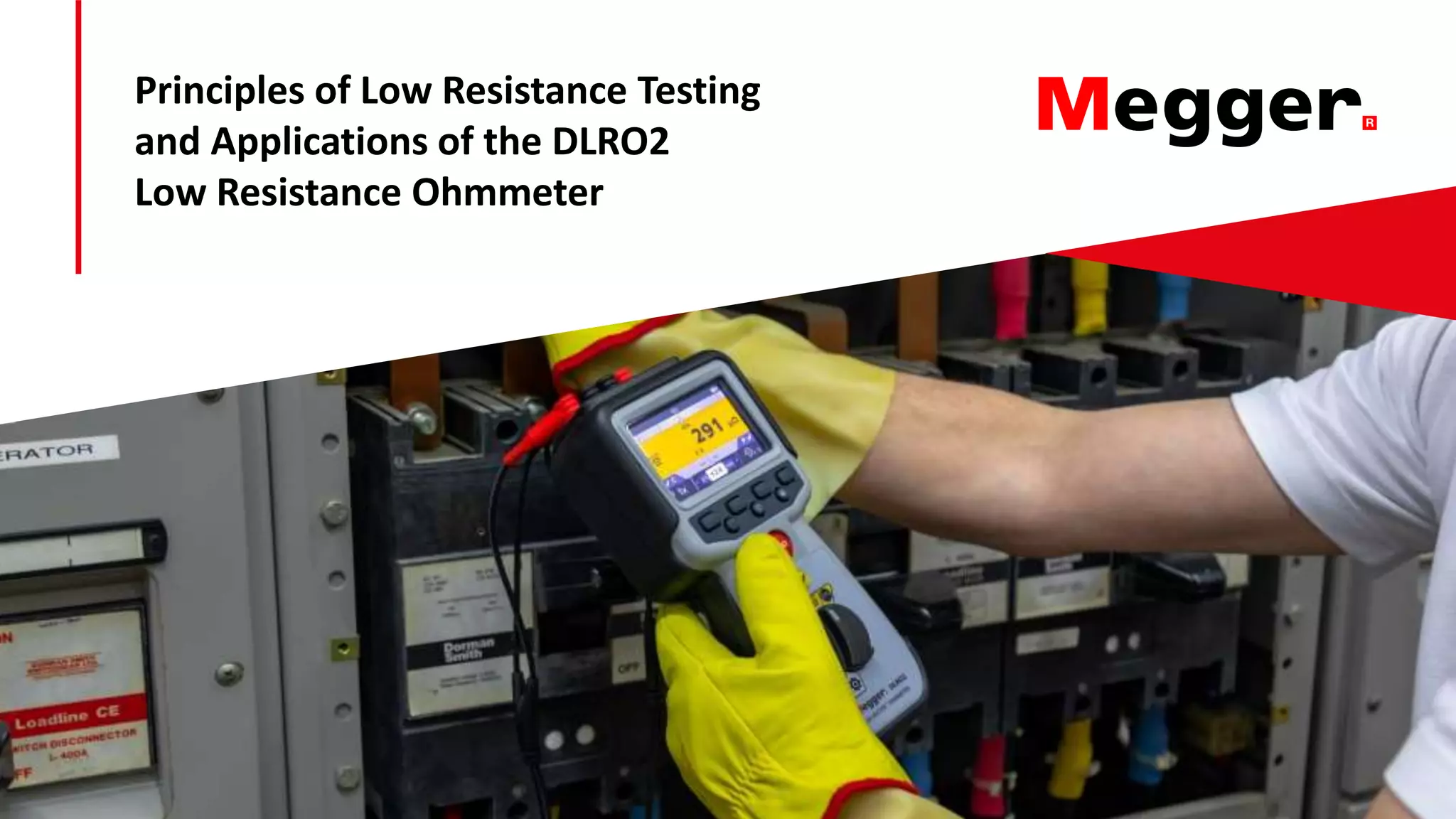
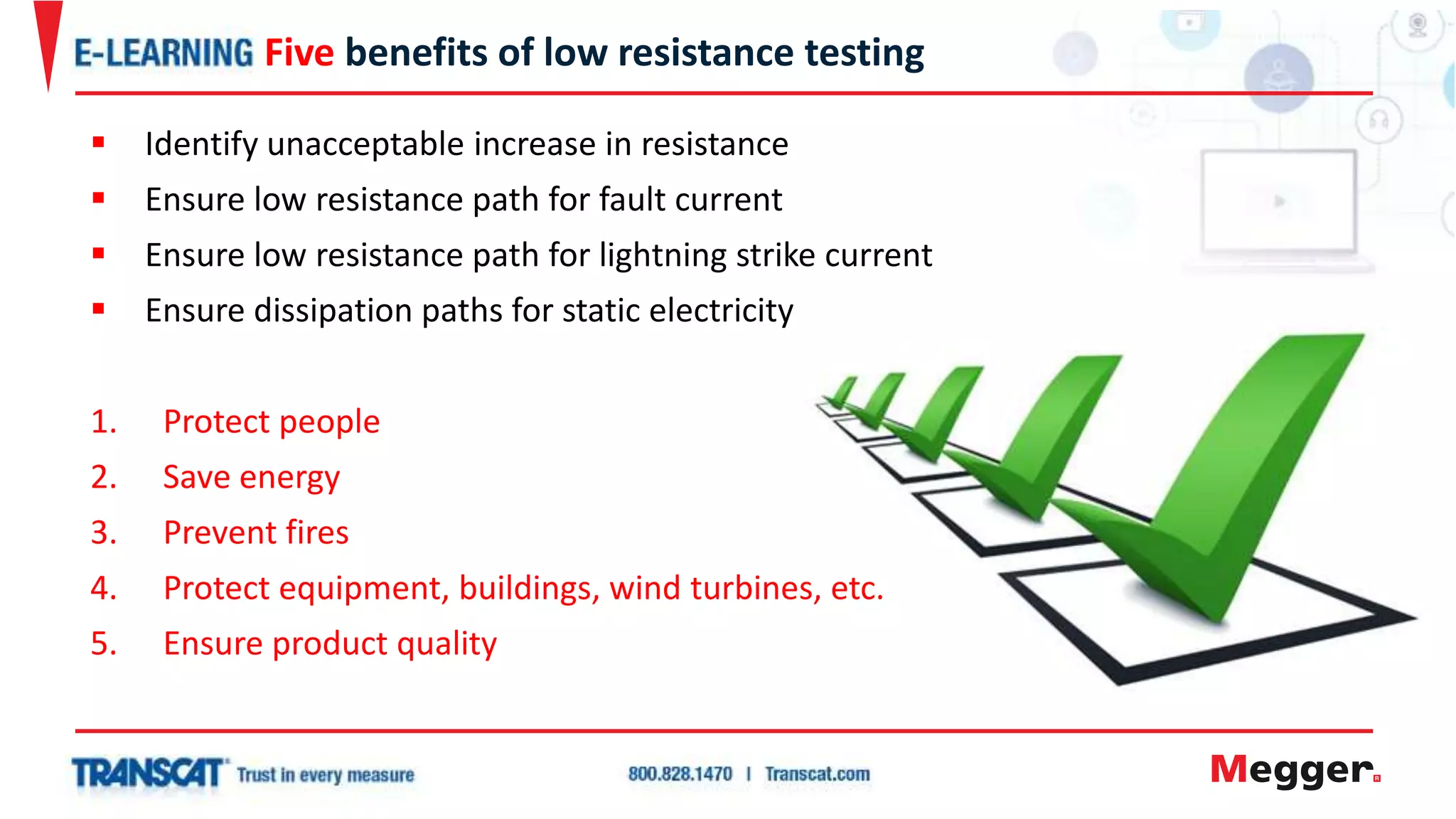
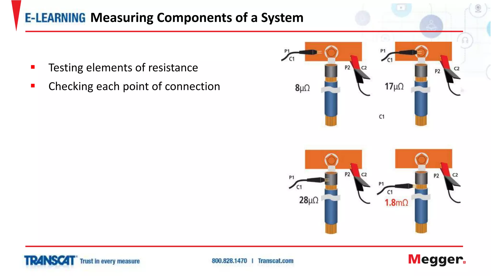
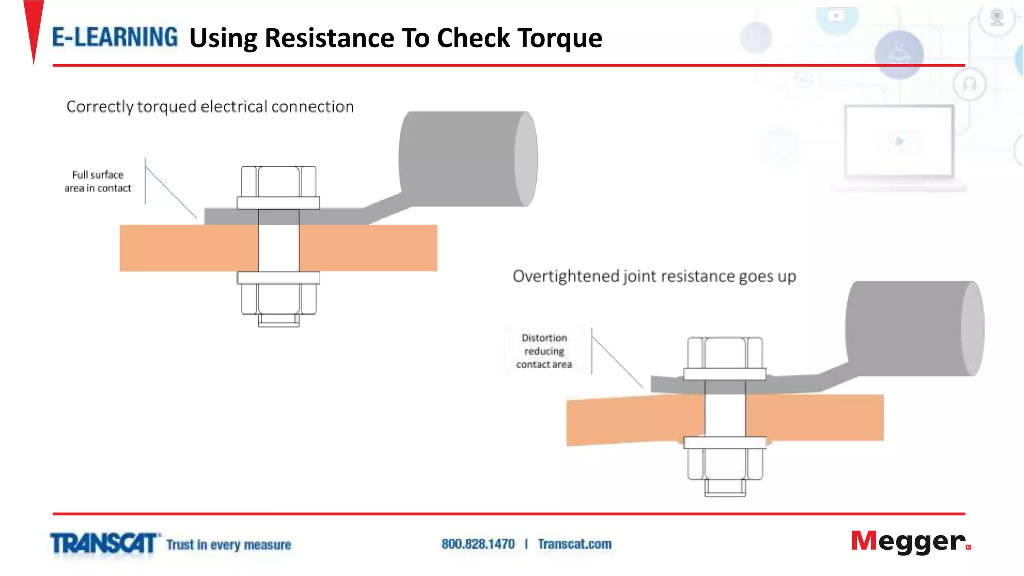
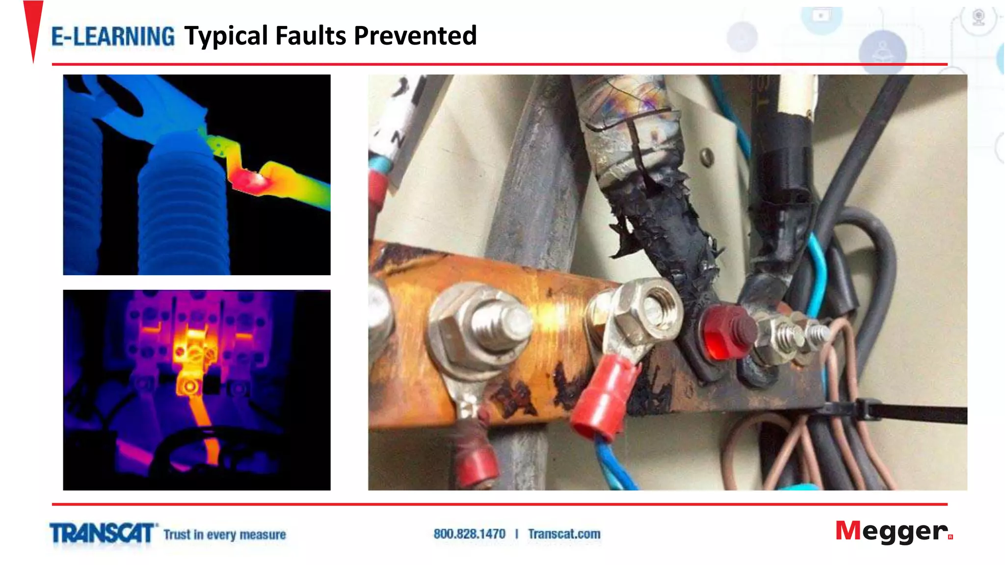
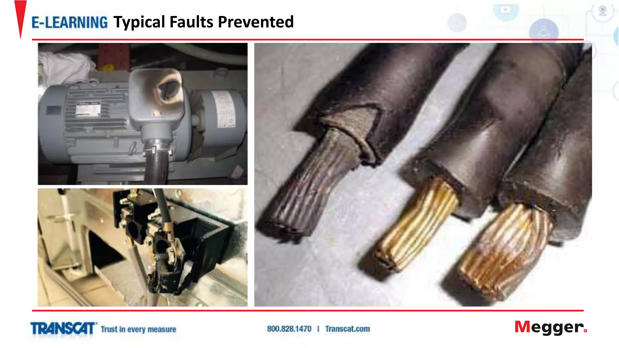
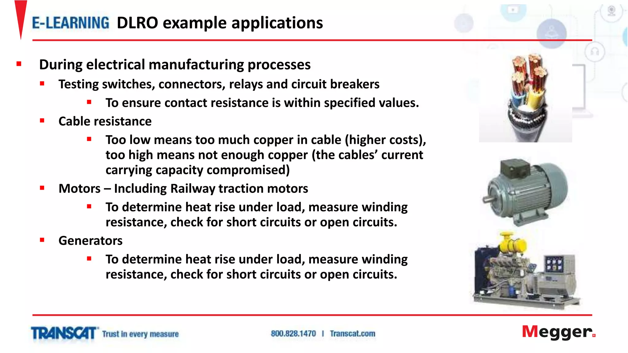
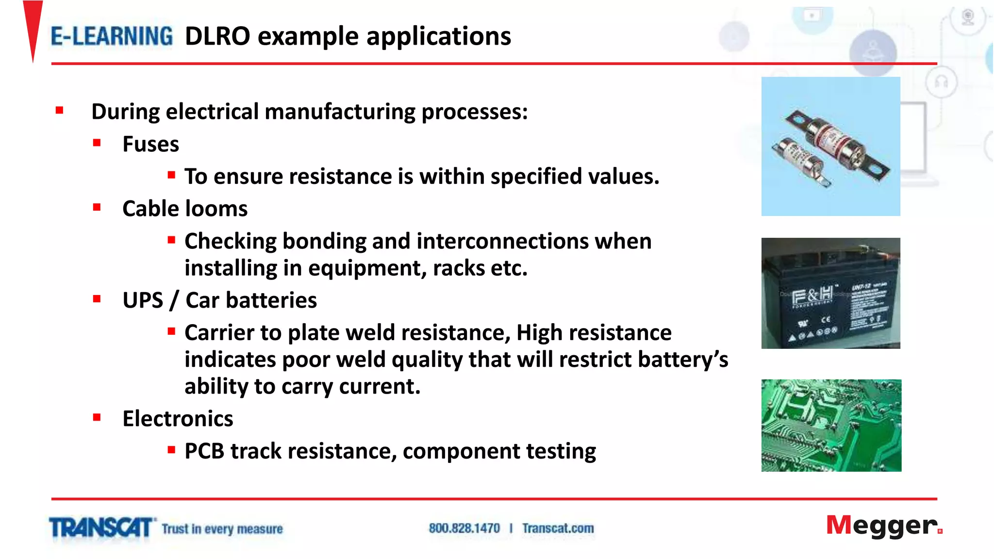
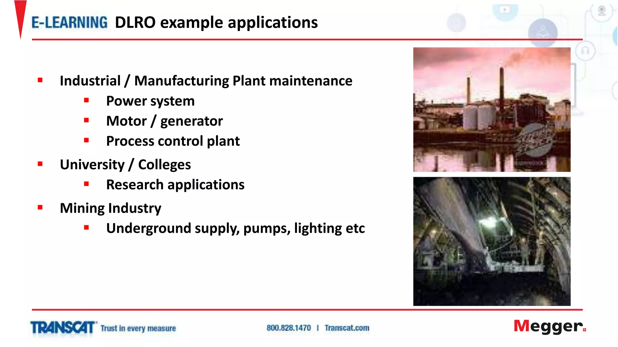
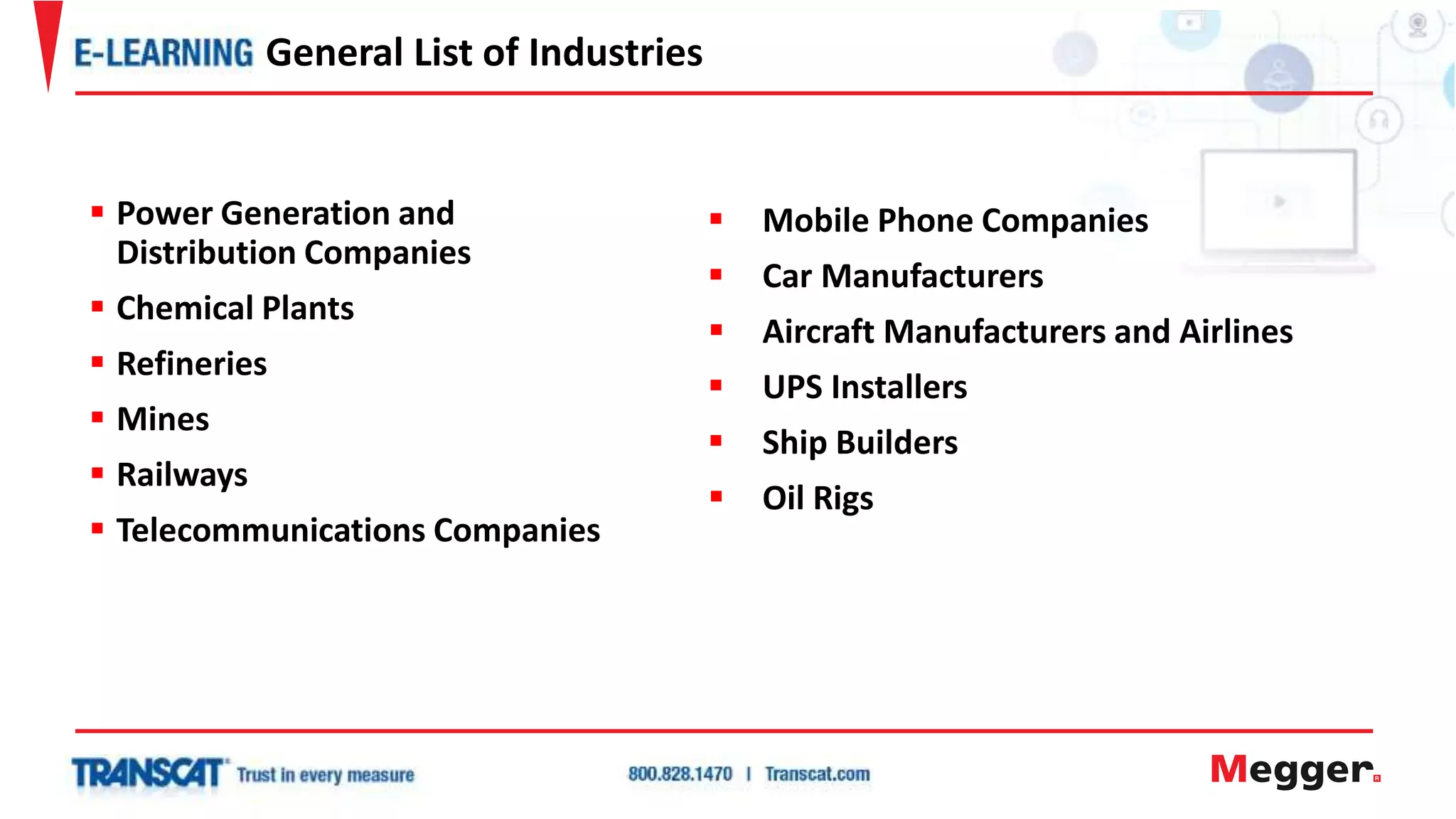
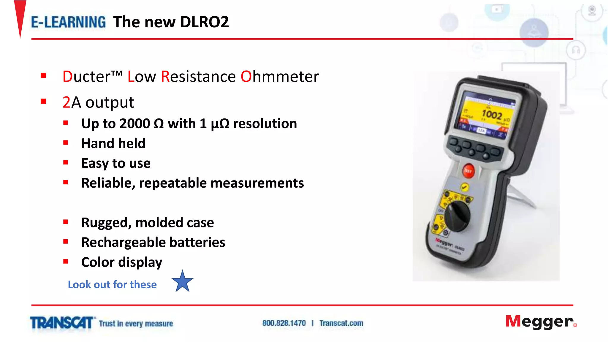
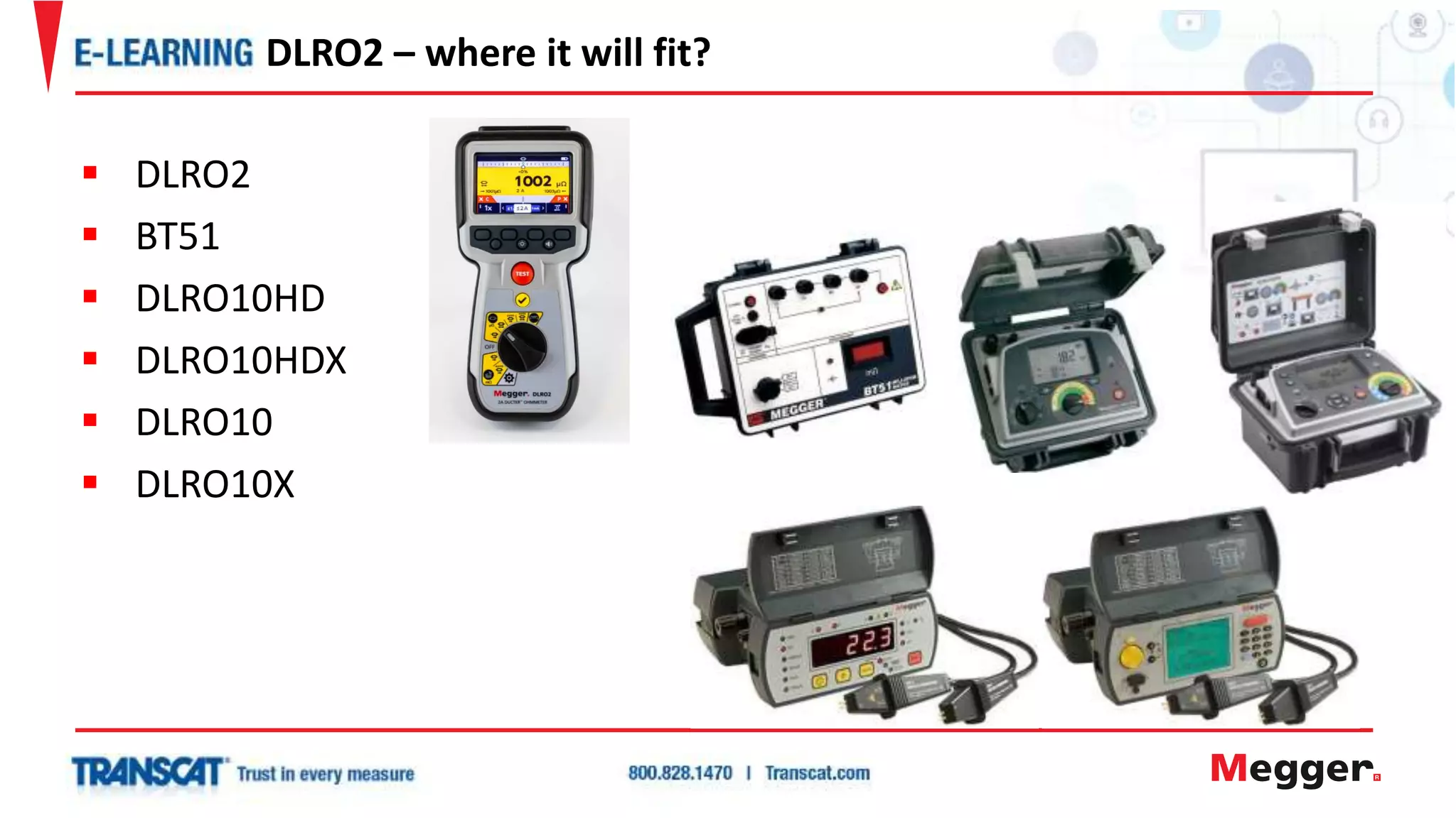
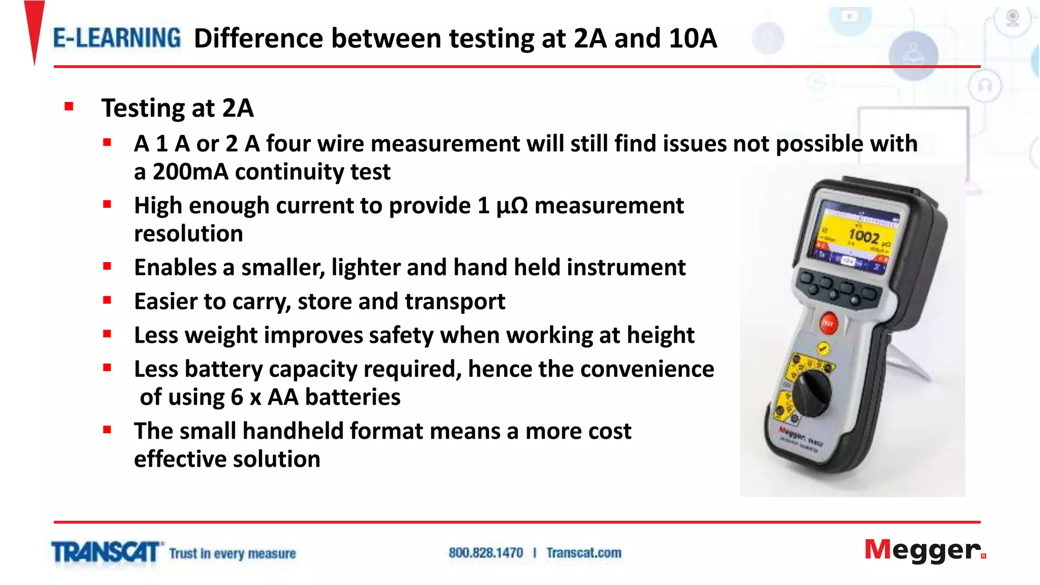
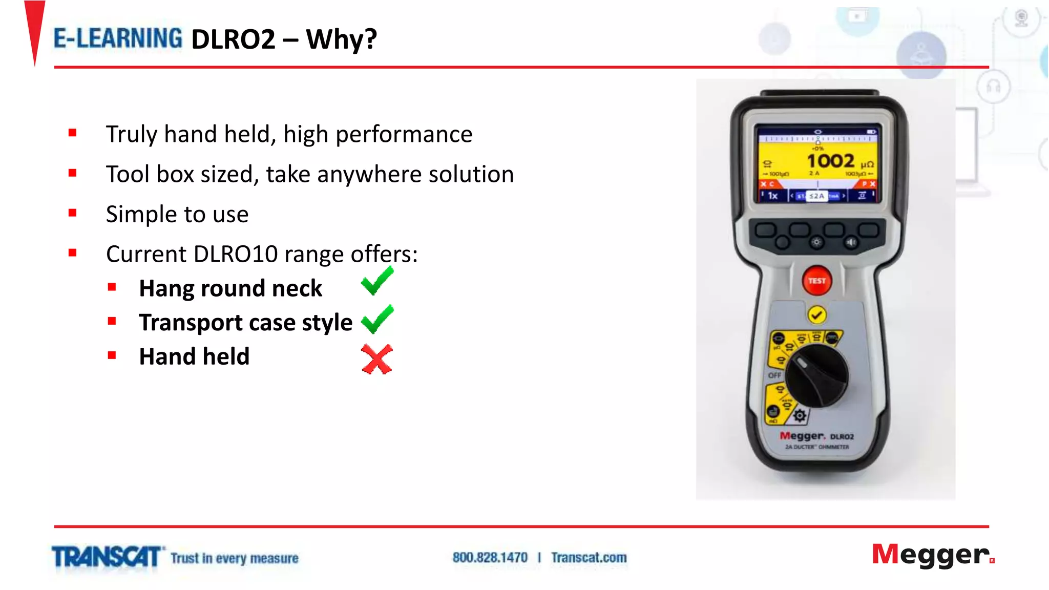
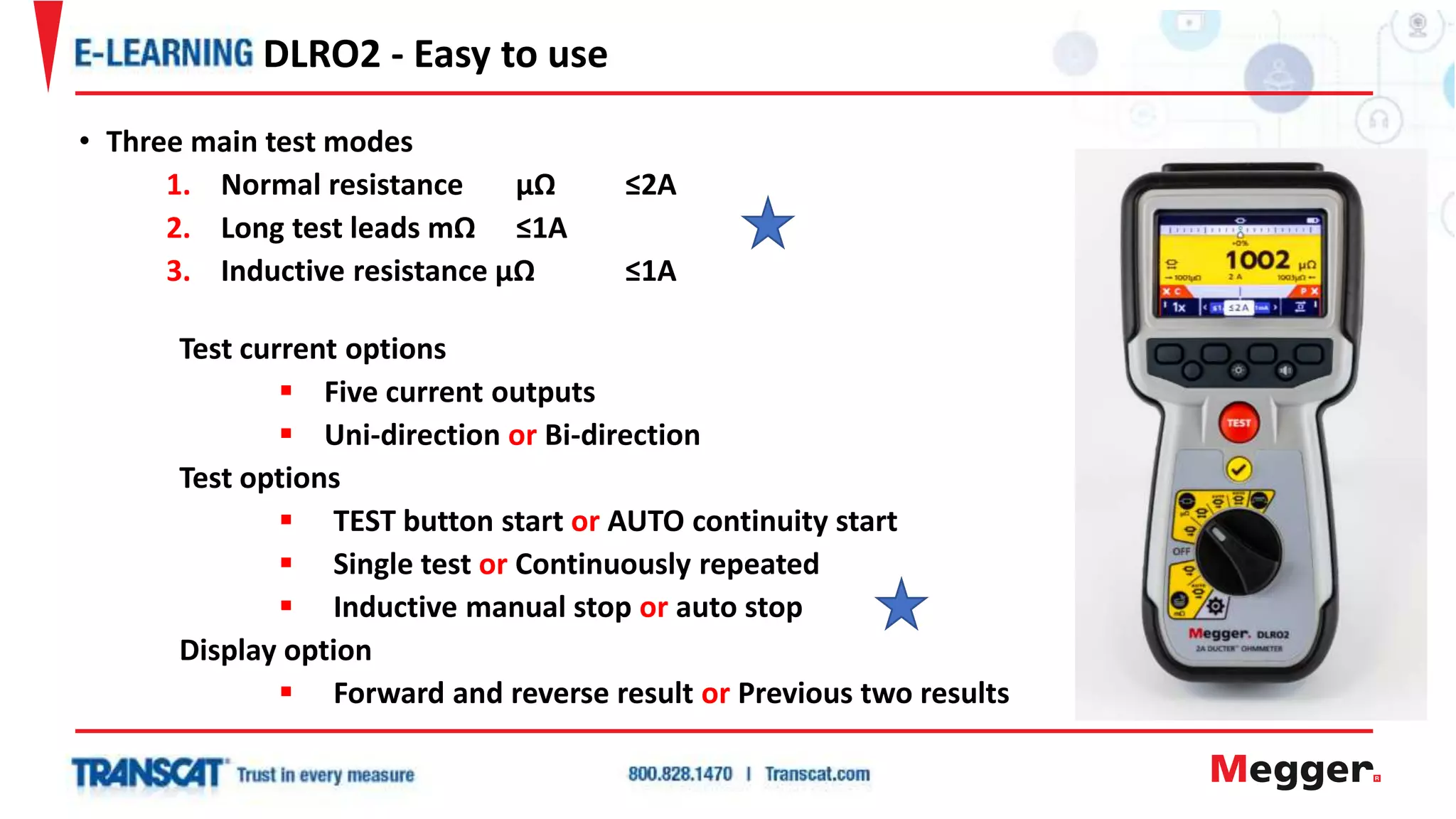
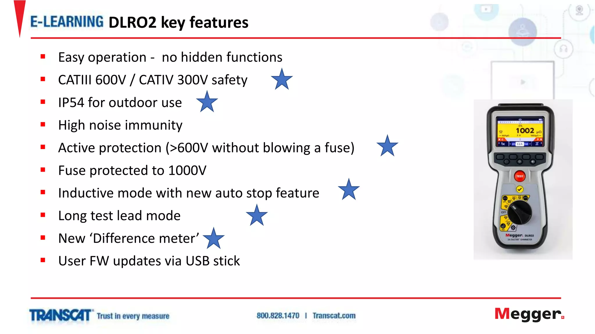
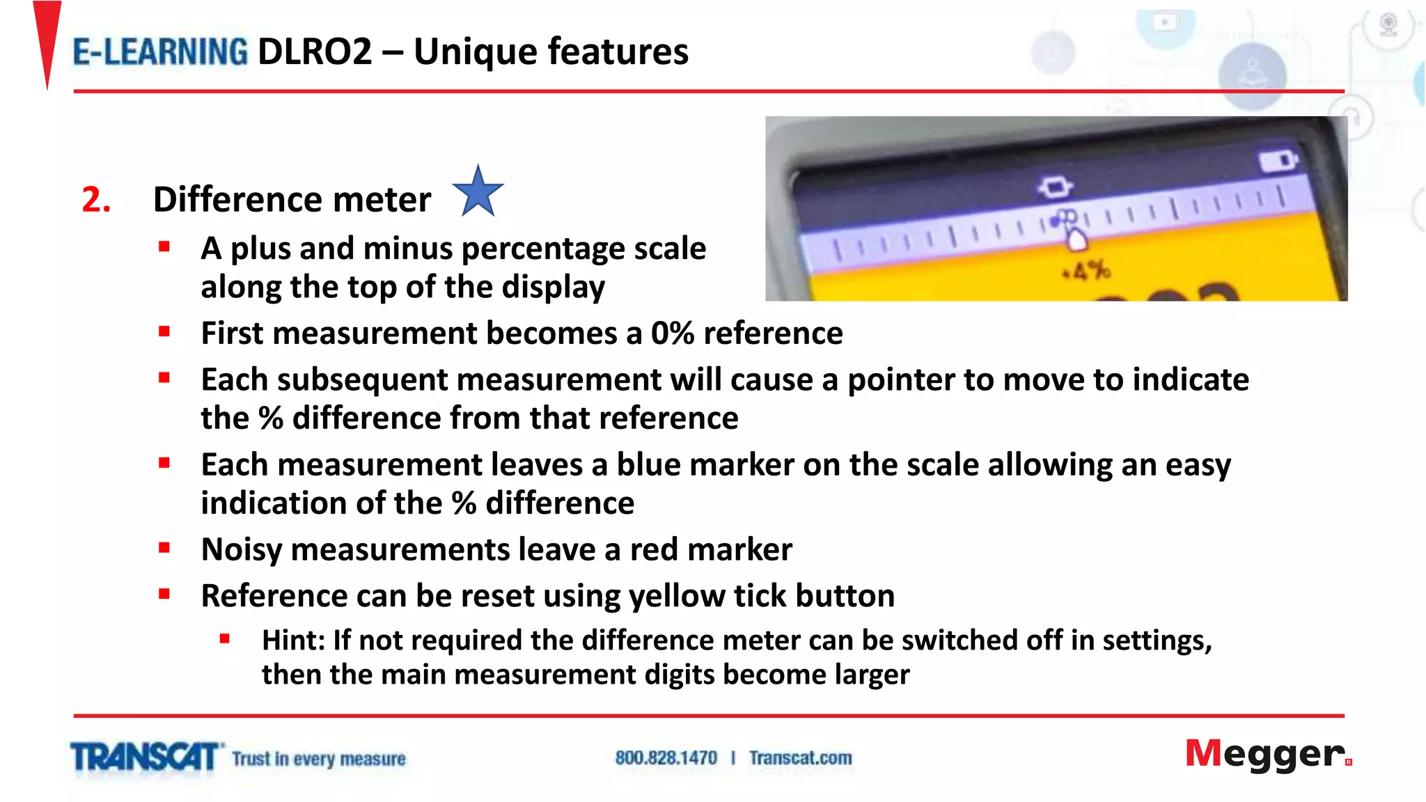
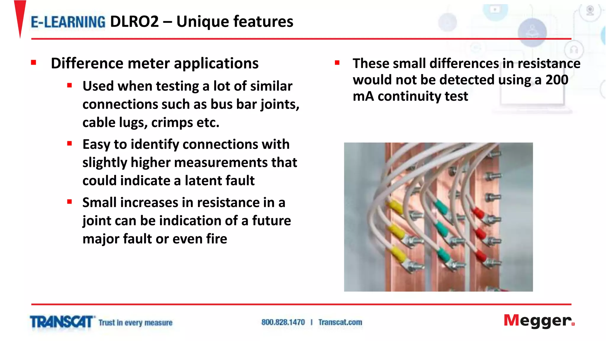
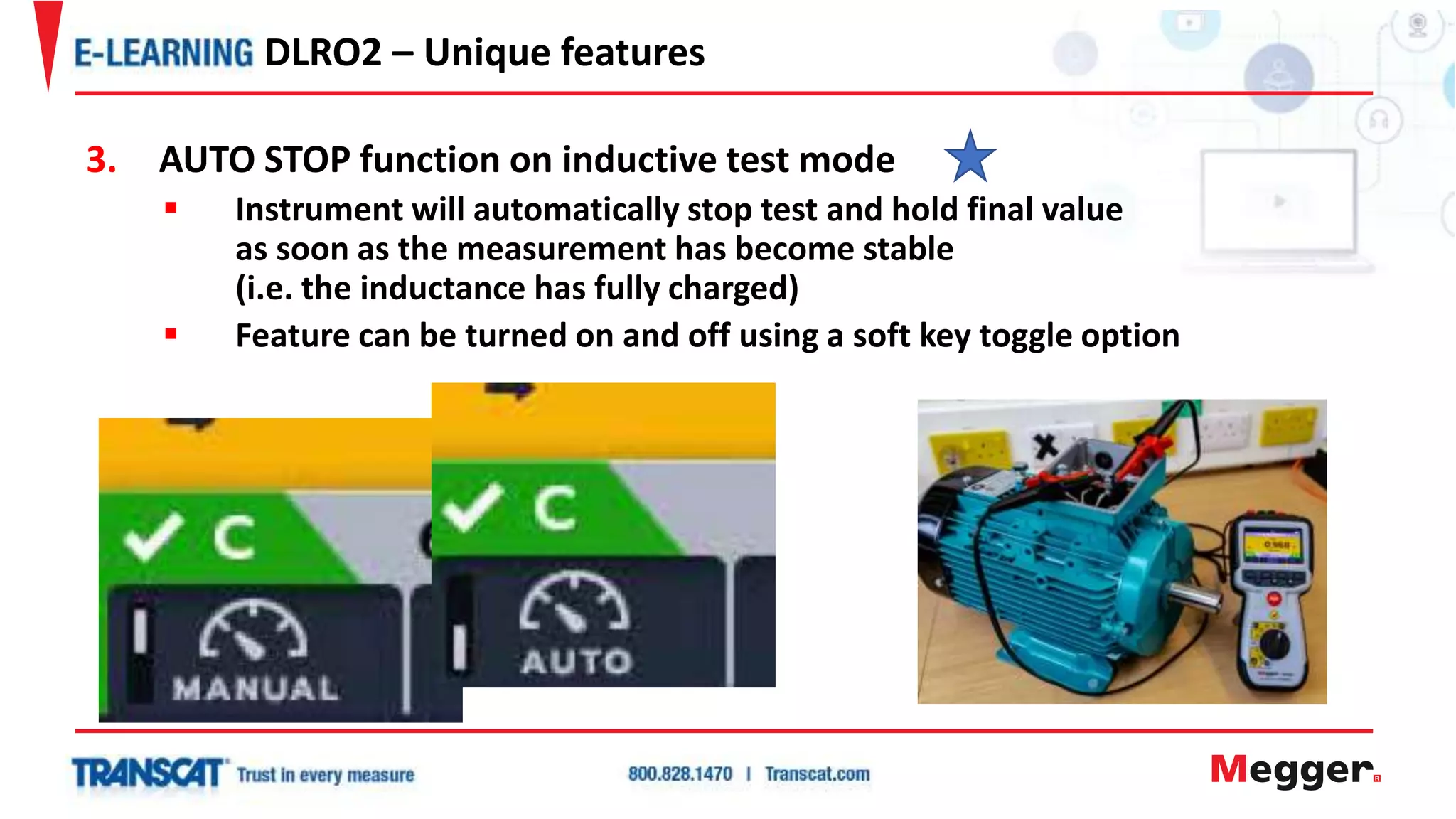
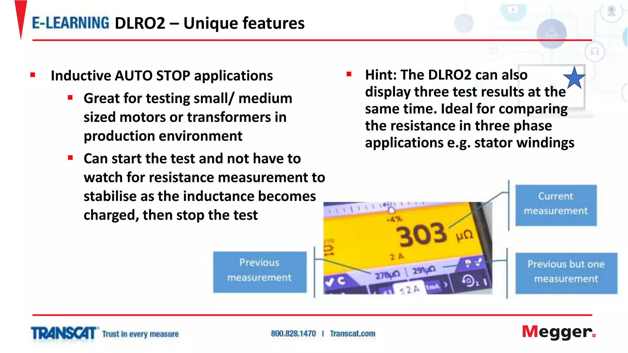
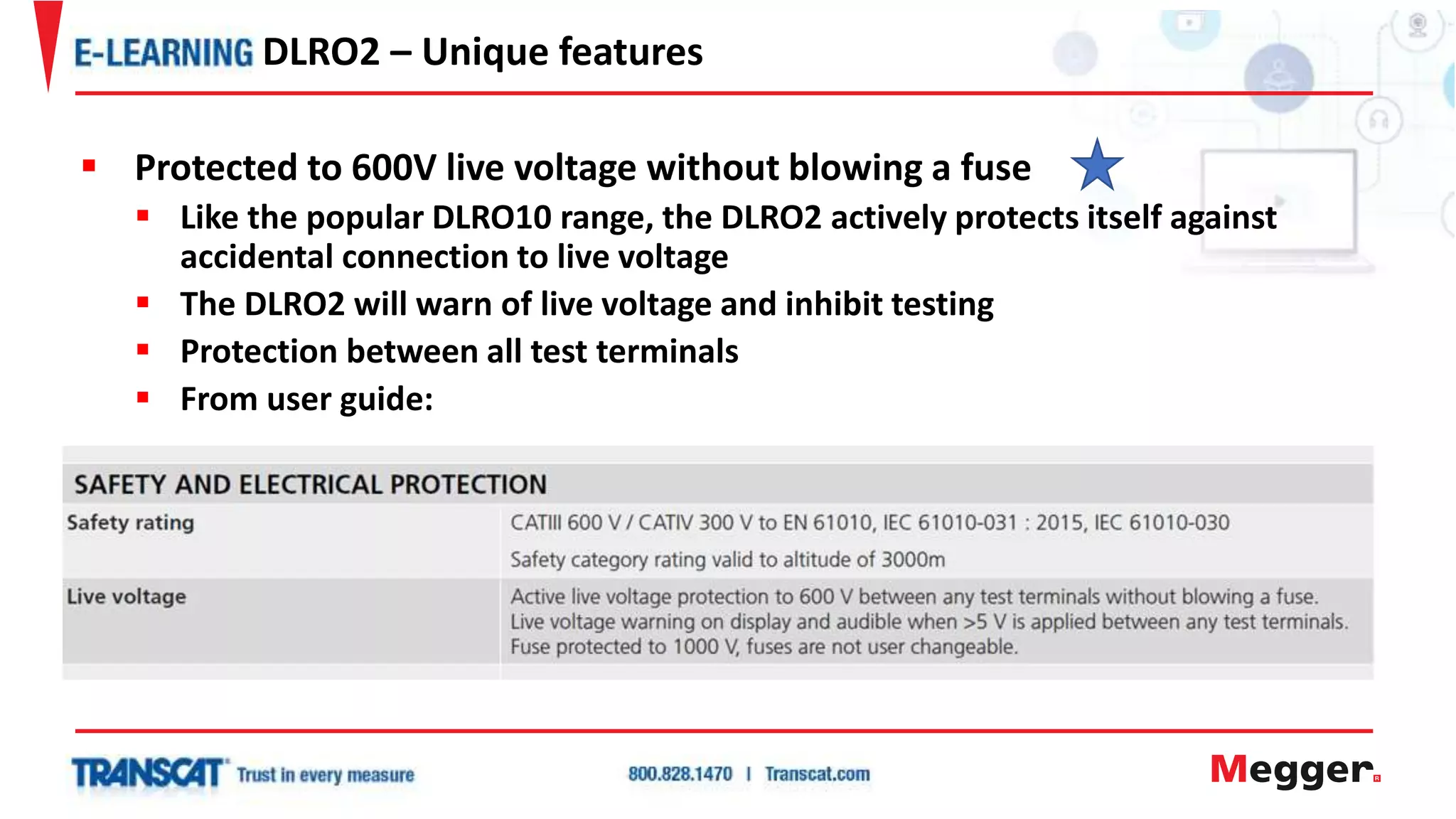
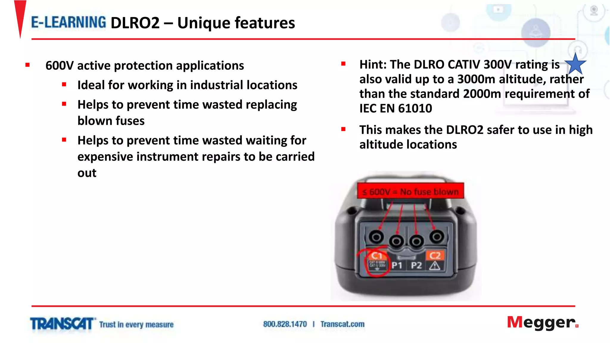
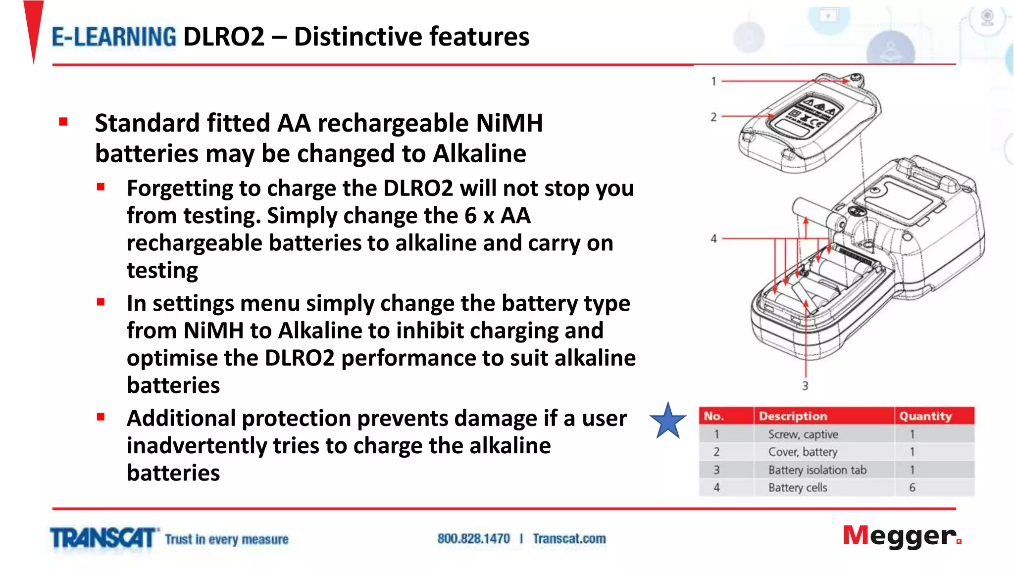
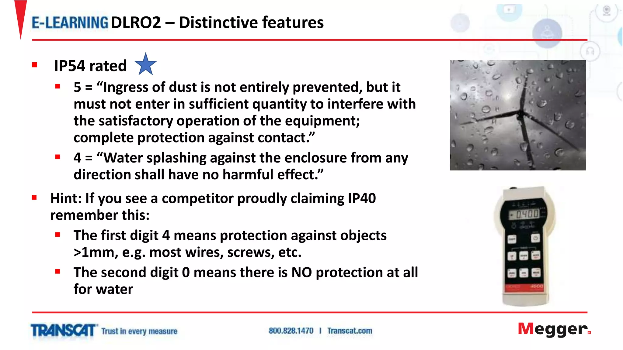
Brian Hammerschmidt, Megger
Principles of Low Resistance Testing
and Applications of the DLRO2
Low Resistance Ohmmeter
 What do our end users want?
 What is considered a Low Resistance Test?
 When to measure Low Resistance
 Why measure Low Resistance?
 Benefits of Low Resistance Testing
 DLRO Example Applications
 DLRO2 – Features and Key Characteristics
 Questions
Outline
 A Digital Low Resistance
Ohmmeter (DLRO)?
What Do Our End Users Really Want?
 Peace of mind
 Reliability
 Cost saving
 Prevention rather than cure
What Do Our End Users Really Want?
 Ducter™ testing or low resistance testing (also known as
contact resistance test) measures the resistance of electrical
connections.
 These can be connections between any two conductors,
for example, cable connections, busbar sections, circuit
breakers, aircraft frame bonds, rail and pipeline bonds,
and many more applications.
What is a low resistance test?
What is considered to be a low resistance test?
 Go/No Go
 Ensure resistance is correct at installation/commissioning
 Condition Monitoring
 Identify unacceptable increase in resistance
 Like Testing
 Ensure ‘like’ elements of a system are of similar resistance
When To Measure Low Resistance?
 Identify unacceptable increase in resistance
 Prevent equipment damage / Increase efficiency
 Low resistance path for fault current
 Fault will always take the path of
lowest resistance
 Low resistance path for lightning strike current
 Static electricity dissipation paths
 Drive predictive maintenance
 Spot the increasing resistance and correct
before it becomes a problem
Why Measure Low Resistance?
 So what causes an increase in resistance?
 Manufacturing / installation or following a repair
 Bolts not tightened enough – or over tightened
 Poor / rough mating surfaces
 Dirty mating surfaces
 Damage
 Frayed wires / broken strands etc.
 Following long periods of shut down
 Corrosion due to dampness
 Chemical attack
Why Measure Low Resistance
 So what causes increase in resistance?
 In service
 Environmental and chemical attack
 Even air will oxidize
 Moisture ingress
 Oil and salt will degrade connections
even more rapidly.
 Chemical corrosion can attack the
mating surfaces
 Electrical stresses
 Over voltages or impulses
Why Measure Low Resistance?
 So what causes increase in resistance?
 Mechanical stress
 Vibration, impact, start / stop
 Metal fatigue
 Equipment heat up and cool down cycles
 Poor solder joints
Why Measure Low Resistance?
 Identify unacceptable increase in resistance
 Ensure low resistance path for fault current
 Ensure low resistance path for lightning strike current
 Ensure dissipation paths for static electricity
1. Protect people
2. Save energy
3. Prevent fires
4. Protect equipment, buildings, wind turbines, etc.
5. Ensure product quality
Five benefits of low resistance testing
DLRO EXAMPLE
APPLICATIONS
 Testing elements of resistance
 Checking each point of connection
Measuring Components of a System
Using Resistance To Check Torque
Typical Faults Prevented
 During electrical manufacturing processes
 Testing switches, connectors, relays and circuit breakers
 To ensure contact resistance is within specified values.
 Cable resistance
 Too low means too much copper in cable (higher costs),
too high means not enough copper (the cables’ current
carrying capacity compromised)
 Motors – Including Railway traction motors
 To determine heat rise under load, measure winding
resistance, check for short circuits or open circuits.
 Generators
 To determine heat rise under load, measure winding
resistance, check for short circuits or open circuits.
DLRO example applications
 During electrical manufacturing processes:
 Fuses
 To ensure resistance is within specified values.
 Cable looms
 Checking bonding and interconnections when
installing in equipment, racks etc.
 UPS / Car batteries
 Carrier to plate weld resistance, High resistance
indicates poor weld quality that will restrict battery’s
ability to carry current.
 Electronics
 PCB track resistance, component testing
DLRO example applications
 Industrial / Manufacturing Plant maintenance
 Power system
 Motor / generator
 Process control plant
 University / Colleges
 Research applications
 Mining Industry
 Underground supply, pumps, lighting etc
DLRO example applications
 Aircraft assembly and maintenance
 Main frame electrical and mechanical bonds –
to ensure a stable “ground plan” to protect
aircraft from static electricity and
lightning strikes.
 Static wick bonding
 Antenna bonds
 Control linkage bonding
 Battery connection and interconnection
 Integrity of structure and exhaust system
 Metallic coating resistance
DLRO example applications
 Aluminium refineries
 Graphite electrodes – to verify density
 Ship building or any metal structures
 Weld quality – measure at regular intervals along weld length
looking for uniformity.
 Installed equipment bonds – to steel structure / hull.
 Raw material processing, e.g. cement plants
 Power carrying elements – installation and maintenance
 Ground bonds - cement is corrosive
 Automotive industry – car, van, commercial vehicle
 Cable leads in robot spot welders work-harden through flexing
causing strands to break. Results in poor weld quality.
DLRO example applications
 Power Generation and Distribution
 Bus bars – lap joint tests to maintain low resistance, and hence
maintaining efficiency and reducing likely hood of fire.
 Cable joints – including overhead lines. High impedance joint can
explode.
 Fuses – connections
 Uninterruptible Power Supply (UPS)
 Battery straps – quality of connections. Preventing potential of
fire and failure to operate
 Carrier to plate weld resistance – High resistance indicates poor
weld quality that will restrict battery’s ability to carry current.
 Military vehicles – Trucks, tanks etc.
 Installed equipment such as radio equipment - ground bonding
to vehicle chassis.
DLRO example applications
 Buildings – wiring, lightning protection bonds
 Various bonds, both for power distribution and earth
grounding – check for step and touch voltage safety in fault
condition.
 Conduit continuity – metal conduit, detect corroded or loose
threads etc.
 Wind turbines – manufacturing and installation
 Lightning protection – wing tip to base, or component parts
in manufacture. Long test leads available for this
application.
 Earth ground bonds – various
DLRO example applications
 Mobile Phone Companies
 Car Manufacturers
 Aircraft Manufacturers and Airlines
 UPS Installers
 Ship Builders
 Oil Rigs
 Power Generation and
Distribution Companies
 Chemical Plants
 Refineries
 Mines
 Railways
 Telecommunications Companies
General List of Industries
 Better than insurance…
Insurance picks up the pieces when
things go wrong…
….Low resistance testing prevents
it from going wrong
The low down of low resistance testing
 Ducter™ Low Resistance Ohmmeter
 2A output
 Up to 2000 Ω with 1 µΩ resolution
 Hand held
 Easy to use
 Reliable, repeatable measurements
 Rugged, molded case
 Rechargeable batteries
 Color display
The new DLRO2
Look out for these
 DLRO2
 BT51
 DLRO10HD
 DLRO10HDX
 DLRO10
 DLRO10X
DLRO2 – where it will fit?
 Testing at 10A
 Higher current provides better ability to heat and expose weaknesses
 DLRO2 maximum power output = 4 W
 DLRO10HD maximum power output = 25 W
Difference between testing at 2A and 10A
DLRO10HD
Difference between testing at 2A and 10A
 Testing at 10A
 Ability to select both very low currents and higher
currents like 10A provide an element of diagnosis with
the ability to find issues such as contamination and
current carrying weaknesses
 Large format of 10A testers allows use of much larger
batteries and therefore improved battery life
DLRO10
DLRO10X
 Testing at 2A
 A 1 A or 2 A four wire measurement will still find issues not possible with
a 200mA continuity test
 High enough current to provide 1 µΩ measurement
resolution
 Enables a smaller, lighter and hand held instrument
 Easier to carry, store and transport
 Less weight improves safety when working at height
 Less battery capacity required, hence the convenience
of using 6 x AA batteries
 The small handheld format means a more cost
effective solution
Difference between testing at 2A and 10A
 Truly hand held, high performance
 Tool box sized, take anywhere solution
 Simple to use
 Current DLRO10 range offers:
 Hang round neck
 Transport case style
 Hand held
DLRO2 – Why?
• Three main test modes
1. Normal resistance µΩ ≤2A
2. Long test leads mΩ ≤1A
3. Inductive resistance µΩ ≤1A
Test current options
 Five current outputs
 Uni-direction or Bi-direction
Test options
 TEST button start or AUTO continuity start
 Single test or Continuously repeated
 Inductive manual stop or auto stop
Display option
 Forward and reverse result or Previous two results
DLRO2 - Easy to use
 Easy operation - no hidden functions
 CATIII 600V / CATIV 300V safety
 IP54 for outdoor use
 High noise immunity
 Active protection (>600V without blowing a fuse)
 Fuse protected to 1000V
 Inductive mode with new auto stop feature
 Long test lead mode
 New ‘Difference meter’
 User FW updates via USB stick
DLRO2 key features
1. Long test lead / mΩ test mode
 Separate, easy to select test mode that optimizes the
instrument for use with very long test leads
 Only tests at 1 A with positive only output tolerance
to comply with 1A minimum current requirements for
wind turbine and aerospace requirements
 Can apply 1A in a total resistance of up to 3 Ω,
allowing potentially over 150m (492 feet) of test
cable to be used
DLRO2 – Unique features
 New cable reels for DLRO2
Lower cost, lighter weight
 Lower weight = safer
DLRO10 performing test
 Long test lead / mΩ test mode
applications
 Testing lightning protection on
wind turbines
 Testing aircraft bonding and
resistance between lightning
receptors
 Subsea cable laying - testing
safety ground connections
DLRO2 – Unique features
2. Difference meter
 A plus and minus percentage scale
along the top of the display
 First measurement becomes a 0% reference
 Each subsequent measurement will cause a pointer to move to indicate
the % difference from that reference
 Each measurement leaves a blue marker on the scale allowing an easy
indication of the % difference
 Noisy measurements leave a red marker
 Reference can be reset using yellow tick button
 Hint: If not required the difference meter can be switched off in settings,
then the main measurement digits become larger
DLRO2 – Unique features
 These small differences in resistance
would not be detected using a 200
mA continuity test
DLRO2 – Unique features
 Difference meter applications
 Used when testing a lot of similar
connections such as bus bar joints,
cable lugs, crimps etc.
 Easy to identify connections with
slightly higher measurements that
could indicate a latent fault
 Small increases in resistance in a
joint can be indication of a future
major fault or even fire
3. AUTO STOP function on inductive test mode
 Instrument will automatically stop test and hold final value
as soon as the measurement has become stable
(i.e. the inductance has fully charged)
 Feature can be turned on and off using a soft key toggle option
DLRO2 – Unique features
 Hint: The DLRO2 can also
display three test results at the
same time. Ideal for comparing
the resistance in three phase
applications e.g. stator windings
DLRO2 – Unique features
 Inductive AUTO STOP applications
 Great for testing small/ medium
sized motors or transformers in
production environment
 Can start the test and not have to
watch for resistance measurement to
stabilise as the inductance becomes
charged, then stop the test
 Protected to 600V live voltage without blowing a fuse
 Like the popular DLRO10 range, the DLRO2 actively protects itself against
accidental connection to live voltage
 The DLRO2 will warn of live voltage and inhibit testing
 Protection between all test terminals
 From user guide:
DLRO2 – Unique features
 Hint: The DLRO CATIV 300V rating is
also valid up to a 3000m altitude, rather
than the standard 2000m requirement of
IEC EN 61010
 This makes the DLRO2 safer to use in high
altitude locations
DLRO2 – Unique features
 600V active protection applications
 Ideal for working in industrial locations
 Helps to prevent time wasted replacing
blown fuses
 Helps to prevent time wasted waiting for
expensive instrument repairs to be carried
out
 Standard fitted AA rechargeable NiMH
batteries may be changed to Alkaline
 Forgetting to charge the DLRO2 will not stop you
from testing. Simply change the 6 x AA
rechargeable batteries to alkaline and carry on
testing
 In settings menu simply change the battery type
from NiMH to Alkaline to inhibit charging and
optimise the DLRO2 performance to suit alkaline
batteries
 Additional protection prevents damage if a user
inadvertently tries to charge the alkaline
batteries
DLRO2 – Distinctive features
 IP54 rated
 5 = “Ingress of dust is not entirely prevented, but it
must not enter in sufficient quantity to interfere with
the satisfactory operation of the equipment;
complete protection against contact.”
 4 = “Water splashing against the enclosure from any
direction shall have no harmful effect.”
 Hint: If you see a competitor proudly claiming IP40
remember this:
 The first digit 4 means protection against objects
>1mm, e.g. most wires, screws, etc.
 The second digit 0 means there is NO protection at all
for water
DLRO2 – Distinctive features
 Display settings
 The yellow display may be changed to white in the
instrument settings
 Increased contrast is ideal for reading in direct sunlight
 The difference meter may be turned off
 With difference meter switch off, the main display digits
become larger – making it easier to read
DLRO2 – Other useful features
DLRO2
High performance in a
hand held instrument
Questions?
Email Christina Spearman christina.spearman@transcat.com
Transcat: 800-828-1470
www.transcat.com
For related product information, go to:
www.transcat.com/brand/megger-store

Principals of Low Resistance Testing Webinar with Megger

  • 1.
  • 2.
    Principles of LowResistance Testing and Applications of the DLRO2 Low Resistance Ohmmeter
  • 3.
     What doour end users want?  What is considered a Low Resistance Test?  When to measure Low Resistance  Why measure Low Resistance?  Benefits of Low Resistance Testing  DLRO Example Applications  DLRO2 – Features and Key Characteristics  Questions Outline
  • 4.
     A DigitalLow Resistance Ohmmeter (DLRO)? What Do Our End Users Really Want?
  • 5.
     Peace ofmind  Reliability  Cost saving  Prevention rather than cure What Do Our End Users Really Want?
  • 6.
     Ducter™ testingor low resistance testing (also known as contact resistance test) measures the resistance of electrical connections.  These can be connections between any two conductors, for example, cable connections, busbar sections, circuit breakers, aircraft frame bonds, rail and pipeline bonds, and many more applications. What is a low resistance test?
  • 7.
    What is consideredto be a low resistance test?
  • 8.
    What is consideredto be a low resistance test?
  • 9.
    What is consideredto be a low resistance test?
  • 10.
    What is consideredto be a low resistance test?
  • 11.
     Go/No Go Ensure resistance is correct at installation/commissioning  Condition Monitoring  Identify unacceptable increase in resistance  Like Testing  Ensure ‘like’ elements of a system are of similar resistance When To Measure Low Resistance?
  • 12.
     Identify unacceptableincrease in resistance  Prevent equipment damage / Increase efficiency  Low resistance path for fault current  Fault will always take the path of lowest resistance  Low resistance path for lightning strike current  Static electricity dissipation paths  Drive predictive maintenance  Spot the increasing resistance and correct before it becomes a problem Why Measure Low Resistance?
  • 13.
     So whatcauses an increase in resistance?  Manufacturing / installation or following a repair  Bolts not tightened enough – or over tightened  Poor / rough mating surfaces  Dirty mating surfaces  Damage  Frayed wires / broken strands etc.  Following long periods of shut down  Corrosion due to dampness  Chemical attack Why Measure Low Resistance
  • 14.
     So whatcauses increase in resistance?  In service  Environmental and chemical attack  Even air will oxidize  Moisture ingress  Oil and salt will degrade connections even more rapidly.  Chemical corrosion can attack the mating surfaces  Electrical stresses  Over voltages or impulses Why Measure Low Resistance?
  • 15.
     So whatcauses increase in resistance?  Mechanical stress  Vibration, impact, start / stop  Metal fatigue  Equipment heat up and cool down cycles  Poor solder joints Why Measure Low Resistance?
  • 16.
     Identify unacceptableincrease in resistance  Ensure low resistance path for fault current  Ensure low resistance path for lightning strike current  Ensure dissipation paths for static electricity 1. Protect people 2. Save energy 3. Prevent fires 4. Protect equipment, buildings, wind turbines, etc. 5. Ensure product quality Five benefits of low resistance testing
  • 17.
  • 18.
     Testing elementsof resistance  Checking each point of connection Measuring Components of a System
  • 19.
    Using Resistance ToCheck Torque
  • 20.
  • 21.
  • 22.
     During electricalmanufacturing processes  Testing switches, connectors, relays and circuit breakers  To ensure contact resistance is within specified values.  Cable resistance  Too low means too much copper in cable (higher costs), too high means not enough copper (the cables’ current carrying capacity compromised)  Motors – Including Railway traction motors  To determine heat rise under load, measure winding resistance, check for short circuits or open circuits.  Generators  To determine heat rise under load, measure winding resistance, check for short circuits or open circuits. DLRO example applications
  • 23.
     During electricalmanufacturing processes:  Fuses  To ensure resistance is within specified values.  Cable looms  Checking bonding and interconnections when installing in equipment, racks etc.  UPS / Car batteries  Carrier to plate weld resistance, High resistance indicates poor weld quality that will restrict battery’s ability to carry current.  Electronics  PCB track resistance, component testing DLRO example applications
  • 24.
     Industrial /Manufacturing Plant maintenance  Power system  Motor / generator  Process control plant  University / Colleges  Research applications  Mining Industry  Underground supply, pumps, lighting etc DLRO example applications
  • 25.
     Aircraft assemblyand maintenance  Main frame electrical and mechanical bonds – to ensure a stable “ground plan” to protect aircraft from static electricity and lightning strikes.  Static wick bonding  Antenna bonds  Control linkage bonding  Battery connection and interconnection  Integrity of structure and exhaust system  Metallic coating resistance DLRO example applications
  • 26.
     Aluminium refineries Graphite electrodes – to verify density  Ship building or any metal structures  Weld quality – measure at regular intervals along weld length looking for uniformity.  Installed equipment bonds – to steel structure / hull.  Raw material processing, e.g. cement plants  Power carrying elements – installation and maintenance  Ground bonds - cement is corrosive  Automotive industry – car, van, commercial vehicle  Cable leads in robot spot welders work-harden through flexing causing strands to break. Results in poor weld quality. DLRO example applications
  • 27.
     Power Generationand Distribution  Bus bars – lap joint tests to maintain low resistance, and hence maintaining efficiency and reducing likely hood of fire.  Cable joints – including overhead lines. High impedance joint can explode.  Fuses – connections  Uninterruptible Power Supply (UPS)  Battery straps – quality of connections. Preventing potential of fire and failure to operate  Carrier to plate weld resistance – High resistance indicates poor weld quality that will restrict battery’s ability to carry current.  Military vehicles – Trucks, tanks etc.  Installed equipment such as radio equipment - ground bonding to vehicle chassis. DLRO example applications
  • 28.
     Buildings –wiring, lightning protection bonds  Various bonds, both for power distribution and earth grounding – check for step and touch voltage safety in fault condition.  Conduit continuity – metal conduit, detect corroded or loose threads etc.  Wind turbines – manufacturing and installation  Lightning protection – wing tip to base, or component parts in manufacture. Long test leads available for this application.  Earth ground bonds – various DLRO example applications
  • 29.
     Mobile PhoneCompanies  Car Manufacturers  Aircraft Manufacturers and Airlines  UPS Installers  Ship Builders  Oil Rigs  Power Generation and Distribution Companies  Chemical Plants  Refineries  Mines  Railways  Telecommunications Companies General List of Industries
  • 30.
     Better thaninsurance… Insurance picks up the pieces when things go wrong… ….Low resistance testing prevents it from going wrong The low down of low resistance testing
  • 31.
     Ducter™ LowResistance Ohmmeter  2A output  Up to 2000 Ω with 1 µΩ resolution  Hand held  Easy to use  Reliable, repeatable measurements  Rugged, molded case  Rechargeable batteries  Color display The new DLRO2 Look out for these
  • 32.
     DLRO2  BT51 DLRO10HD  DLRO10HDX  DLRO10  DLRO10X DLRO2 – where it will fit?
  • 33.
     Testing at10A  Higher current provides better ability to heat and expose weaknesses  DLRO2 maximum power output = 4 W  DLRO10HD maximum power output = 25 W Difference between testing at 2A and 10A DLRO10HD
  • 34.
    Difference between testingat 2A and 10A  Testing at 10A  Ability to select both very low currents and higher currents like 10A provide an element of diagnosis with the ability to find issues such as contamination and current carrying weaknesses  Large format of 10A testers allows use of much larger batteries and therefore improved battery life DLRO10 DLRO10X
  • 35.
     Testing at2A  A 1 A or 2 A four wire measurement will still find issues not possible with a 200mA continuity test  High enough current to provide 1 µΩ measurement resolution  Enables a smaller, lighter and hand held instrument  Easier to carry, store and transport  Less weight improves safety when working at height  Less battery capacity required, hence the convenience of using 6 x AA batteries  The small handheld format means a more cost effective solution Difference between testing at 2A and 10A
  • 36.
     Truly handheld, high performance  Tool box sized, take anywhere solution  Simple to use  Current DLRO10 range offers:  Hang round neck  Transport case style  Hand held DLRO2 – Why?
  • 37.
    • Three maintest modes 1. Normal resistance µΩ ≤2A 2. Long test leads mΩ ≤1A 3. Inductive resistance µΩ ≤1A Test current options  Five current outputs  Uni-direction or Bi-direction Test options  TEST button start or AUTO continuity start  Single test or Continuously repeated  Inductive manual stop or auto stop Display option  Forward and reverse result or Previous two results DLRO2 - Easy to use
  • 38.
     Easy operation- no hidden functions  CATIII 600V / CATIV 300V safety  IP54 for outdoor use  High noise immunity  Active protection (>600V without blowing a fuse)  Fuse protected to 1000V  Inductive mode with new auto stop feature  Long test lead mode  New ‘Difference meter’  User FW updates via USB stick DLRO2 key features
  • 39.
    1. Long testlead / mΩ test mode  Separate, easy to select test mode that optimizes the instrument for use with very long test leads  Only tests at 1 A with positive only output tolerance to comply with 1A minimum current requirements for wind turbine and aerospace requirements  Can apply 1A in a total resistance of up to 3 Ω, allowing potentially over 150m (492 feet) of test cable to be used DLRO2 – Unique features
  • 40.
     New cablereels for DLRO2 Lower cost, lighter weight  Lower weight = safer DLRO10 performing test  Long test lead / mΩ test mode applications  Testing lightning protection on wind turbines  Testing aircraft bonding and resistance between lightning receptors  Subsea cable laying - testing safety ground connections DLRO2 – Unique features
  • 41.
    2. Difference meter A plus and minus percentage scale along the top of the display  First measurement becomes a 0% reference  Each subsequent measurement will cause a pointer to move to indicate the % difference from that reference  Each measurement leaves a blue marker on the scale allowing an easy indication of the % difference  Noisy measurements leave a red marker  Reference can be reset using yellow tick button  Hint: If not required the difference meter can be switched off in settings, then the main measurement digits become larger DLRO2 – Unique features
  • 42.
     These smalldifferences in resistance would not be detected using a 200 mA continuity test DLRO2 – Unique features  Difference meter applications  Used when testing a lot of similar connections such as bus bar joints, cable lugs, crimps etc.  Easy to identify connections with slightly higher measurements that could indicate a latent fault  Small increases in resistance in a joint can be indication of a future major fault or even fire
  • 43.
    3. AUTO STOPfunction on inductive test mode  Instrument will automatically stop test and hold final value as soon as the measurement has become stable (i.e. the inductance has fully charged)  Feature can be turned on and off using a soft key toggle option DLRO2 – Unique features
  • 44.
     Hint: TheDLRO2 can also display three test results at the same time. Ideal for comparing the resistance in three phase applications e.g. stator windings DLRO2 – Unique features  Inductive AUTO STOP applications  Great for testing small/ medium sized motors or transformers in production environment  Can start the test and not have to watch for resistance measurement to stabilise as the inductance becomes charged, then stop the test
  • 45.
     Protected to600V live voltage without blowing a fuse  Like the popular DLRO10 range, the DLRO2 actively protects itself against accidental connection to live voltage  The DLRO2 will warn of live voltage and inhibit testing  Protection between all test terminals  From user guide: DLRO2 – Unique features
  • 46.
     Hint: TheDLRO CATIV 300V rating is also valid up to a 3000m altitude, rather than the standard 2000m requirement of IEC EN 61010  This makes the DLRO2 safer to use in high altitude locations DLRO2 – Unique features  600V active protection applications  Ideal for working in industrial locations  Helps to prevent time wasted replacing blown fuses  Helps to prevent time wasted waiting for expensive instrument repairs to be carried out
  • 47.
     Standard fittedAA rechargeable NiMH batteries may be changed to Alkaline  Forgetting to charge the DLRO2 will not stop you from testing. Simply change the 6 x AA rechargeable batteries to alkaline and carry on testing  In settings menu simply change the battery type from NiMH to Alkaline to inhibit charging and optimise the DLRO2 performance to suit alkaline batteries  Additional protection prevents damage if a user inadvertently tries to charge the alkaline batteries DLRO2 – Distinctive features
  • 48.
     IP54 rated 5 = “Ingress of dust is not entirely prevented, but it must not enter in sufficient quantity to interfere with the satisfactory operation of the equipment; complete protection against contact.”  4 = “Water splashing against the enclosure from any direction shall have no harmful effect.”  Hint: If you see a competitor proudly claiming IP40 remember this:  The first digit 4 means protection against objects >1mm, e.g. most wires, screws, etc.  The second digit 0 means there is NO protection at all for water DLRO2 – Distinctive features
  • 49.
     Display settings The yellow display may be changed to white in the instrument settings  Increased contrast is ideal for reading in direct sunlight  The difference meter may be turned off  With difference meter switch off, the main display digits become larger – making it easier to read DLRO2 – Other useful features
  • 50.
    DLRO2 High performance ina hand held instrument
  • 51.
    Questions? Email Christina Spearmanchristina.spearman@transcat.com Transcat: 800-828-1470 www.transcat.com For related product information, go to: www.transcat.com/brand/megger-store

Editor's Notes

  • #6 It is a lot less expensive to find a problem and correct it – before a total failure occurs.
  • #7 The name “ducter” refers to the original DUCTER™ low resistance ohmmeter was developed by Evershed & Vignoles (one of the companies that evolved into Megger) in 1908. The term Ducter comes from “conductor” – so it is short for “conductor” test.
  • #8 IR testers use high voltage and are able to read very high resistance
  • #10 You’ll notice that continuity testers use 200mA
  • #11 Low Resistance tests are generally considered to be below 1 ohm. These use a higher current and low voltage in order to read very low resistances – to a tenth of a micro ohm. A Four-Wire Kelvin measurement makes it possible to accurately measure resistance values less than 0.1 Ω while eliminating the inherent resistance of the lead wires connecting the measurement instrument to the component being measured.
  • #12 Go/No Go – check correct resistance at install/commissioning – can also set a base line for future measurement comparison. Condition Monitoring – looking for an increase in readings Like Testing – for example, resistance readings on similar joints on bussbar should be close to each other
  • #13 6000 A across a 100 μΩ bus = 3600 Watts. 6000 A across a 1 mΩ (1000 µΩ) bus = 36,000 Watts, which will result in excessive heating. Main frame electrical and mechanical bonds – to ensure a stable “ground plan” to protect aircraft from static electricity and lightning strikes.
  • #17 Again - Low resistance testing is a four terminal test to remove effects of contact resistance and test leads Basically tests very low resistance, much lower than a continuity tester
  • #19 Here is an example of testing on a buss bar – one connection is to the buss bar – then testing each point of connection – 1. to the other side of buss bar 2. to the bolt 3. to the lug 4. to the cable itself below the crimp – here we see an increase in resistance – indicating a poor connection between lug and cable. Again, a DMM (Digital Multi Meter) is not capable of reading these low levels of resistance and detecting an increase as in this example. Megger has run many tests comparing a DMM to a DLRO -- the DMM may provide a resistance reading – but would not detect an increase as in the example above. Detecting this increase allows the customer to address the issue (poor crimp for example) and correct it before the problem becomes more serious – in this case, overheating of the joint – which will eventually lead to complete failure of the joint.
  • #20 This is a common issue – the technician or mechanic comes in and thinks theyre doing a good thing by tightening a connection as much as possible – unfortunately this is not always the best thing to do.
  • #21 These are examples of poor joints that resulted in higher resistance – and this can lead to overheating.
  • #22 High resistance fault in a motor Poor crimps on wires Poor connection on a terminal block
  • #23 Motors and generators – same tests
  • #30 Here's just a general list of industries – I wont read them all, but this is just to show that there is a wide variety of industries that test for low resistance
  • #31 Most people would not go without insurance… If they understood the benefits of low resistance testing they wouldn’t go without a DLRO either
  • #32 The original DUCTER™ low resistance ohmmeter was developed by Evershed & Vignoles (one of the companies that evolved into Megger) in 1908. The term Ducter comes from “conductor” – so it is short for conductor test. First four are key customer requirements based on research 2000 ohm range is useful in production environments for testing component values... This also shows the difference between a really poor connection and a complete open circuit / incorrect connection Last three points are key characteristics * = Focus / distinctive point of the unit
  • #33 Here are the other Megger DLRO models – obviously the DLRO2 is the only hand held model. .
  • #34 Noise immunity can be important when testing in HV substations 25W provides more heat that may expose contamination - for example on large circuit breaker contacts
  • #35 So – the choice between 2A and 10A is dependent on the application.
  • #37 The DLRO2 effectively fills a gap in the low current DLRO range. The current DLRO10 range provides hang round the neck options and the traditional transport case style housing, but there we do not have a hand held option.
  • #38 We’ll talk about the importance of these features in the coming slides. Current outputs: 2A, 1A, 100mA, 10mA and 1mA Normal – for general low resistance testing Long Test Leads mode – for any application requiring long leads (can be over 400 ft) – for example, testing wind turbines Inductive resistance mode – for example, motors Bi-Directional mode: In low resistance tests, thermal emfs (electromotive forces), also known as Seebeck voltage, can produce voltage gradients across the test sample. Although only on the millivolt level, and of little or no influence on common multimeter tests, these can cause fluctuations of several digits. Such instability defeats the purpose of a high precision measurement. In addition, a.c. interference can be induced by nearby electric or magnetic fields, electrical imbalance and so on. This problem is overcome by taking readings in forward and reverse polarity and then averaging them. Unidirectional Mode: Applies a current in one direction only. While this type of measurement does not negate standing emfs, it does speed up the measuring process. In many test conditions, such as battery straps tests, it is not necessary to do a reversed current test on the sample.
  • #39 We’ll go into a little more detail on some of these features in the coming slides. But I’ll mention here that The CAT rating defines the level of transient voltage (voltage spike or surge) the instrument has been designed to withstand.
  • #40 150 meters = 492 feet Why would you need to use 492 feet of cable? See next slide
  • #41 The average height of a wind turbine is about 300 feet (280 ft avg) The new test lead – cable reels – are available in 50 meter (164 ft) and 100 meter (328 ft) lengths.
  • #42 We know from speaking to aerospace (and other) engineers that REPEATABILITY in readings is crucial – many low resistance meters on the market do not provide repeatable and stable readings – The DLRO2 is proven to provide extremely stable and repeatable results – making it perfect for aerospace and other applications – the difference meter provides a quick and simple way to compare readings and clearly see the repeatability of the readings.
  • #44 Inductive loads (such as motors) can sometimes take longer to fully charge – so readings can take longer to stabilize.
  • #45 Again - The auto stop function lets you know that the reading has stabilized – So you can start the test and not have to watch for resistance measurement to stabilise as the inductance becomes charged -then stop the test
  • #47 The CAT rating defines the level of transient (spike or surge) the instrument has been designed to withstand. Transmission lines (overhead or underground) are considered as Category IV because the energy available from the supply and size of a transient is much higher near to the transformer. Test equipment suitable for use in this environment needs to be rated to CAT IV. By the time the transient has passed through the fuse panel into the premises, the circuit impedance is higher and transients are damped (or even suppressed by surge protection devices), reducing the available energy in the transient and the available fault current if an arc does occur. The ability of the test instrument to withstand this surge is less stringent, hence a Category III rating.
  • #49 The IP Code stands for Ingress Protection Code, sometimes referred to as International Protection Code Here's a photo of a competitors unit – this cannot be used in the rain!