Downloaded 873 times
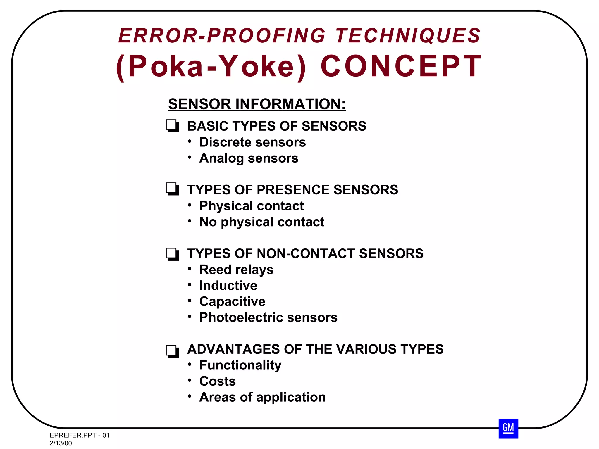
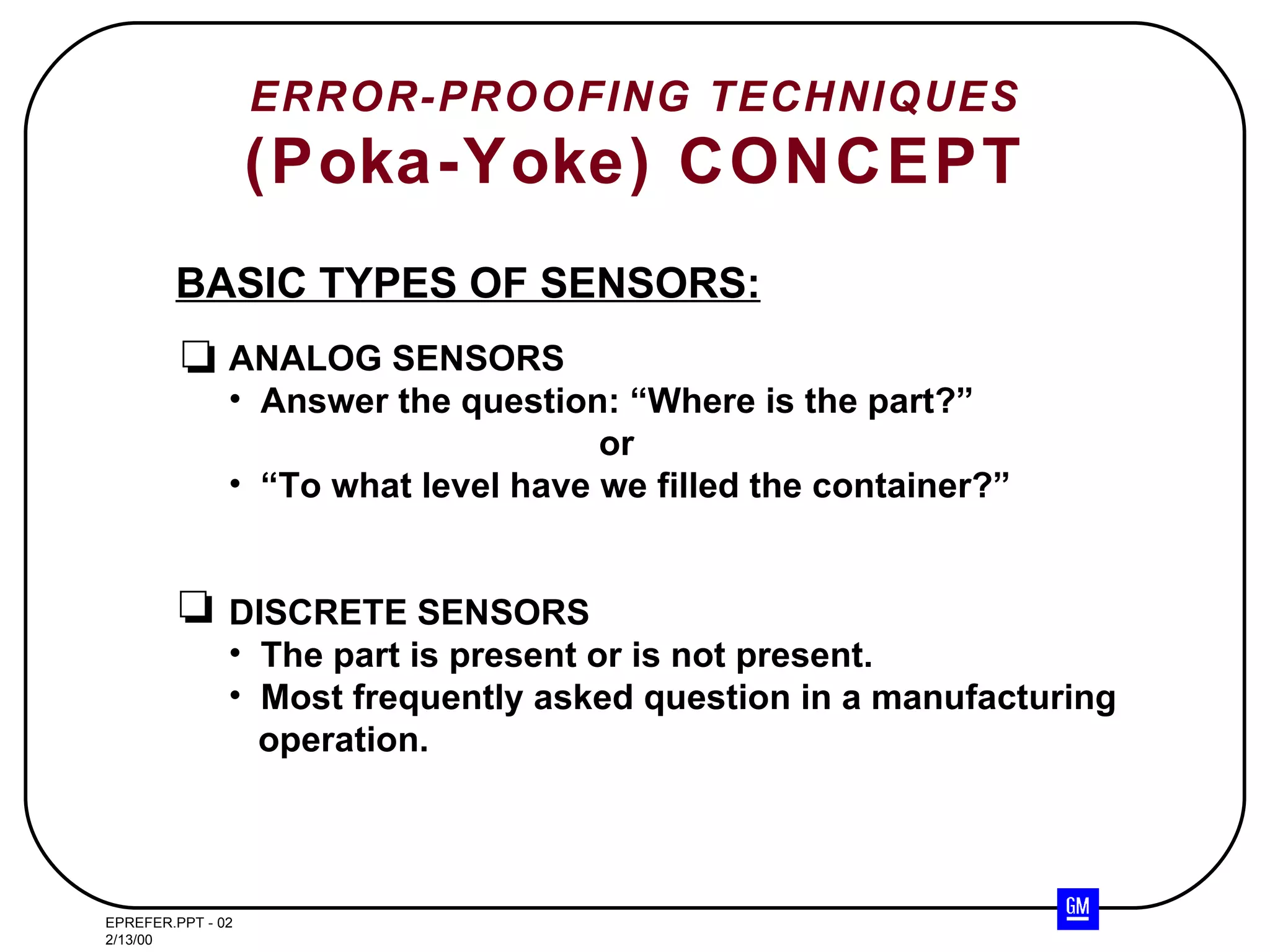
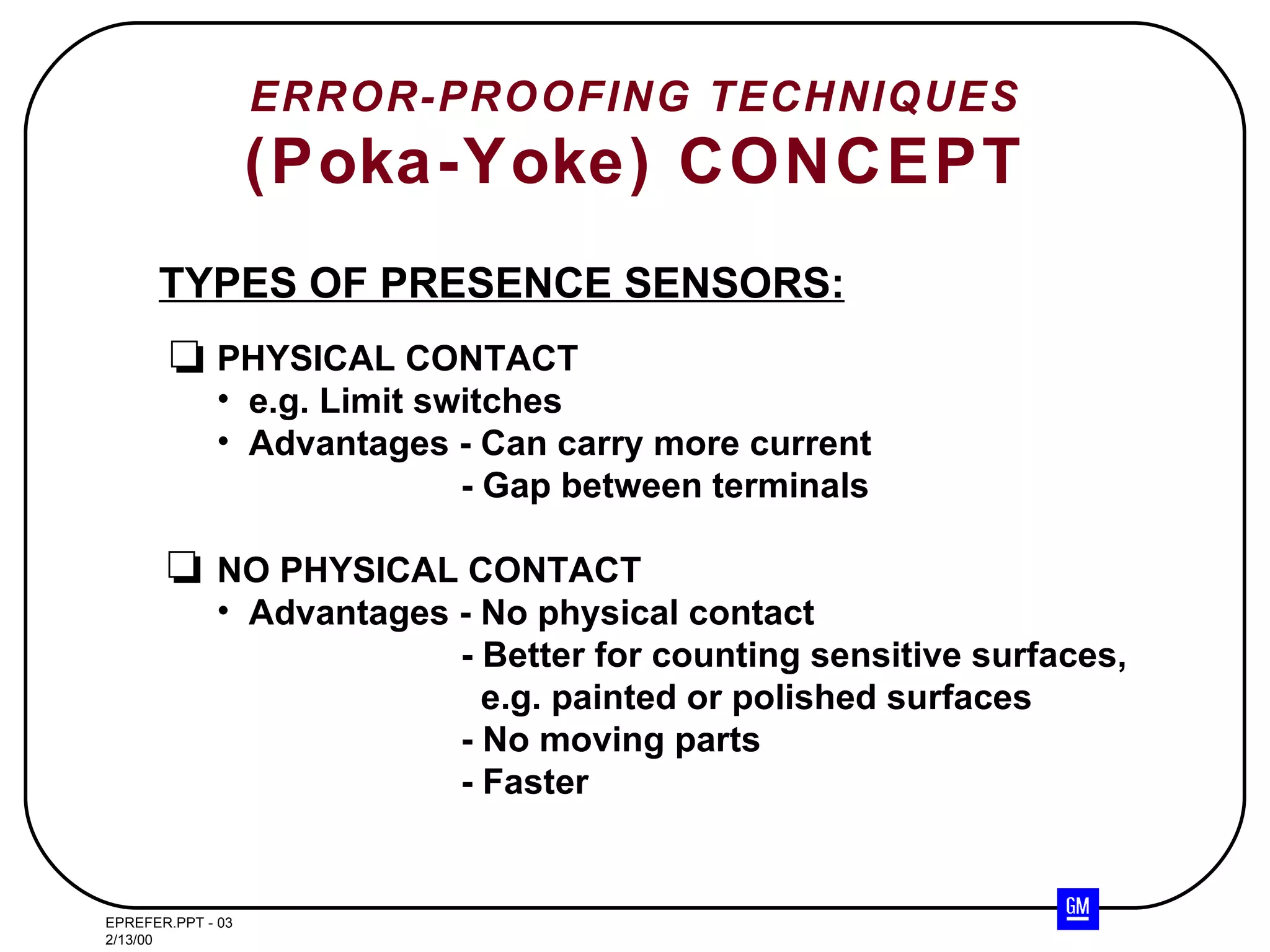
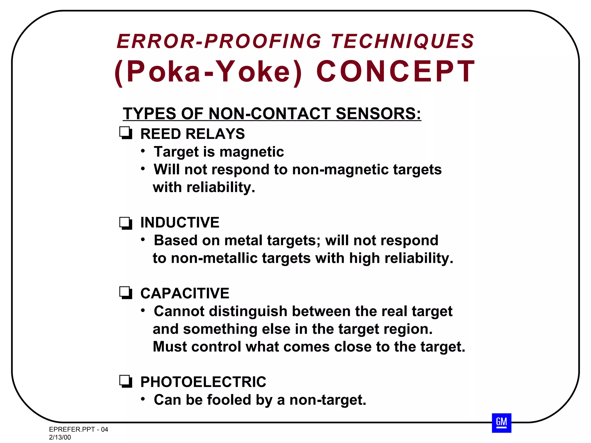
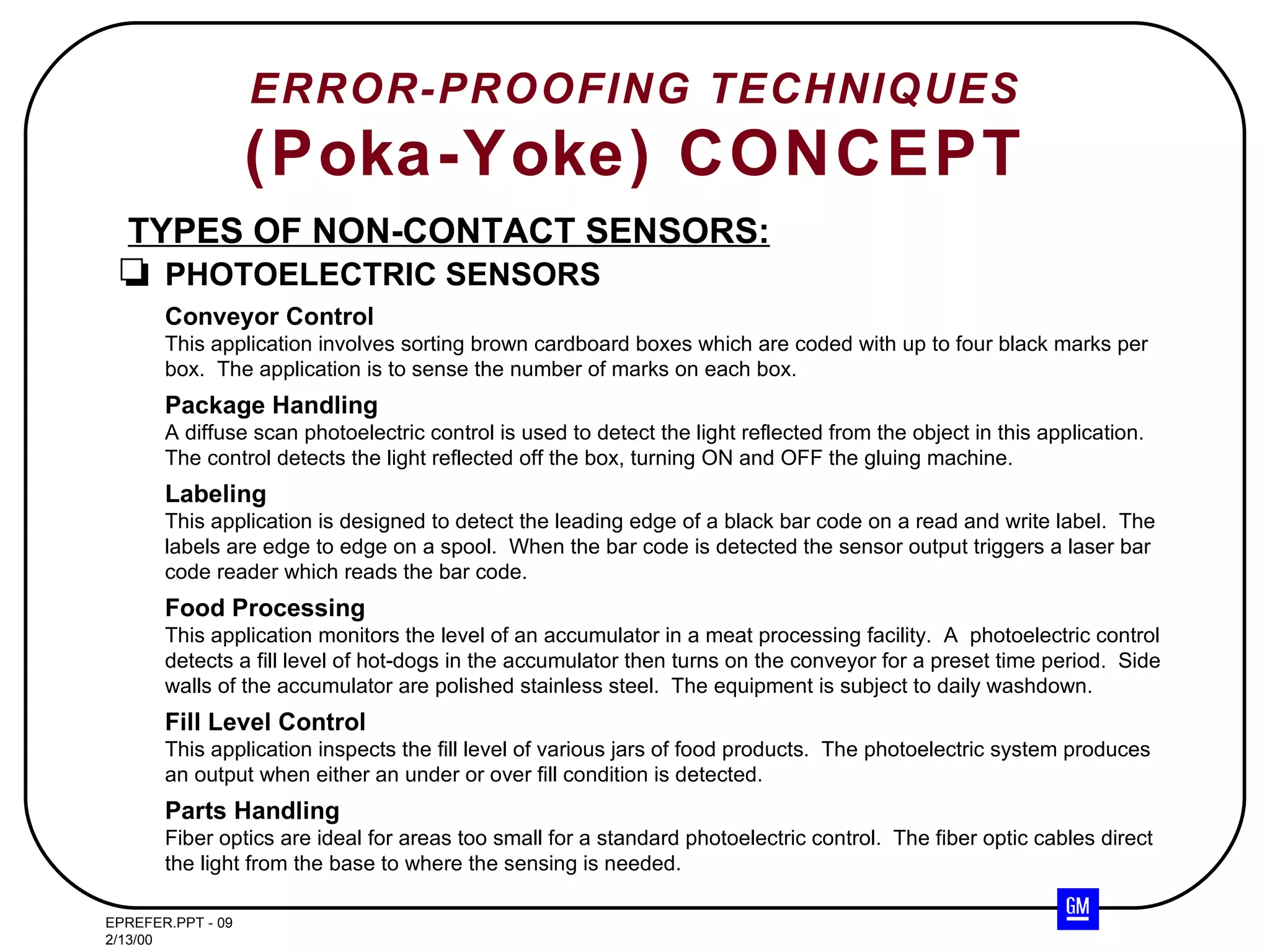
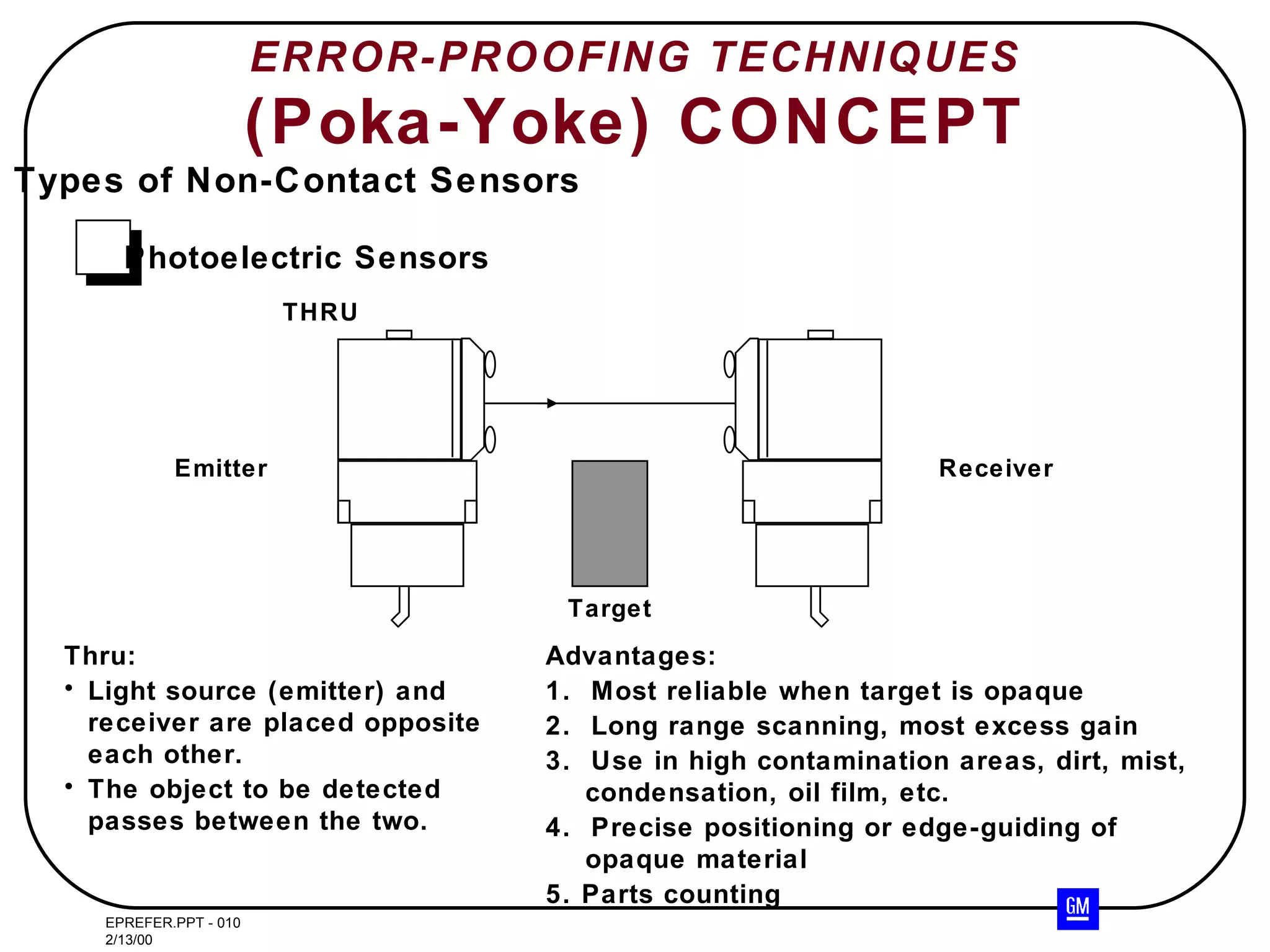
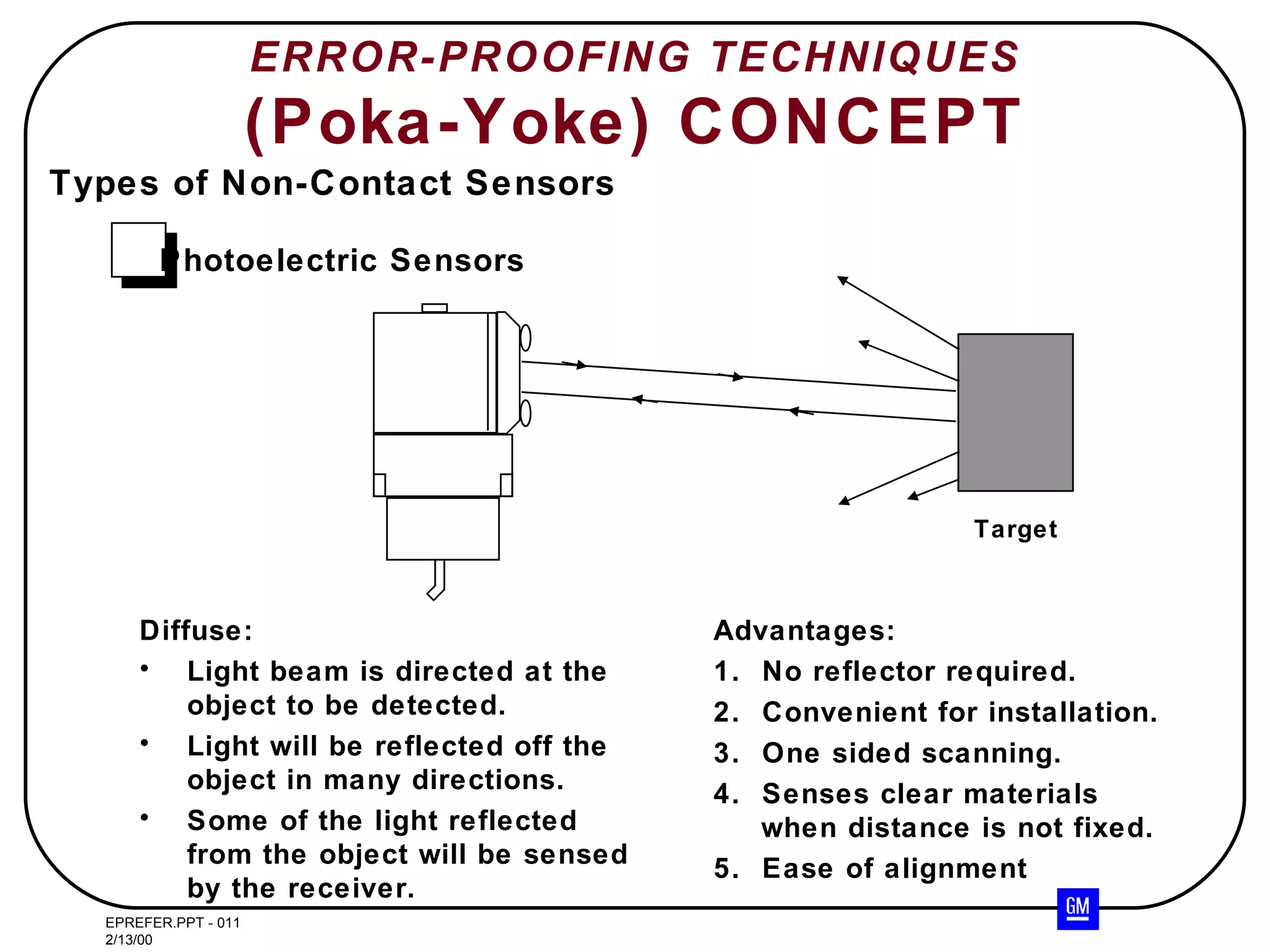
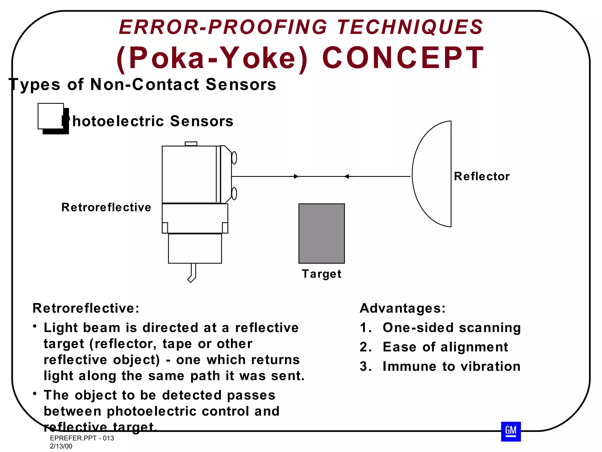
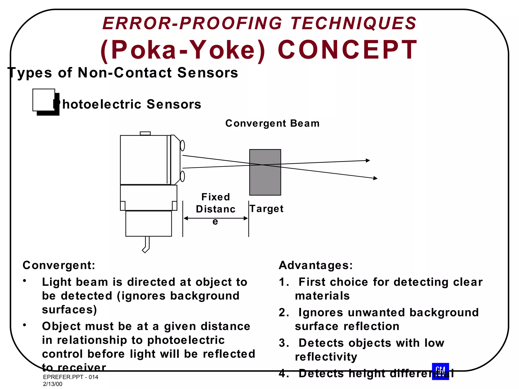
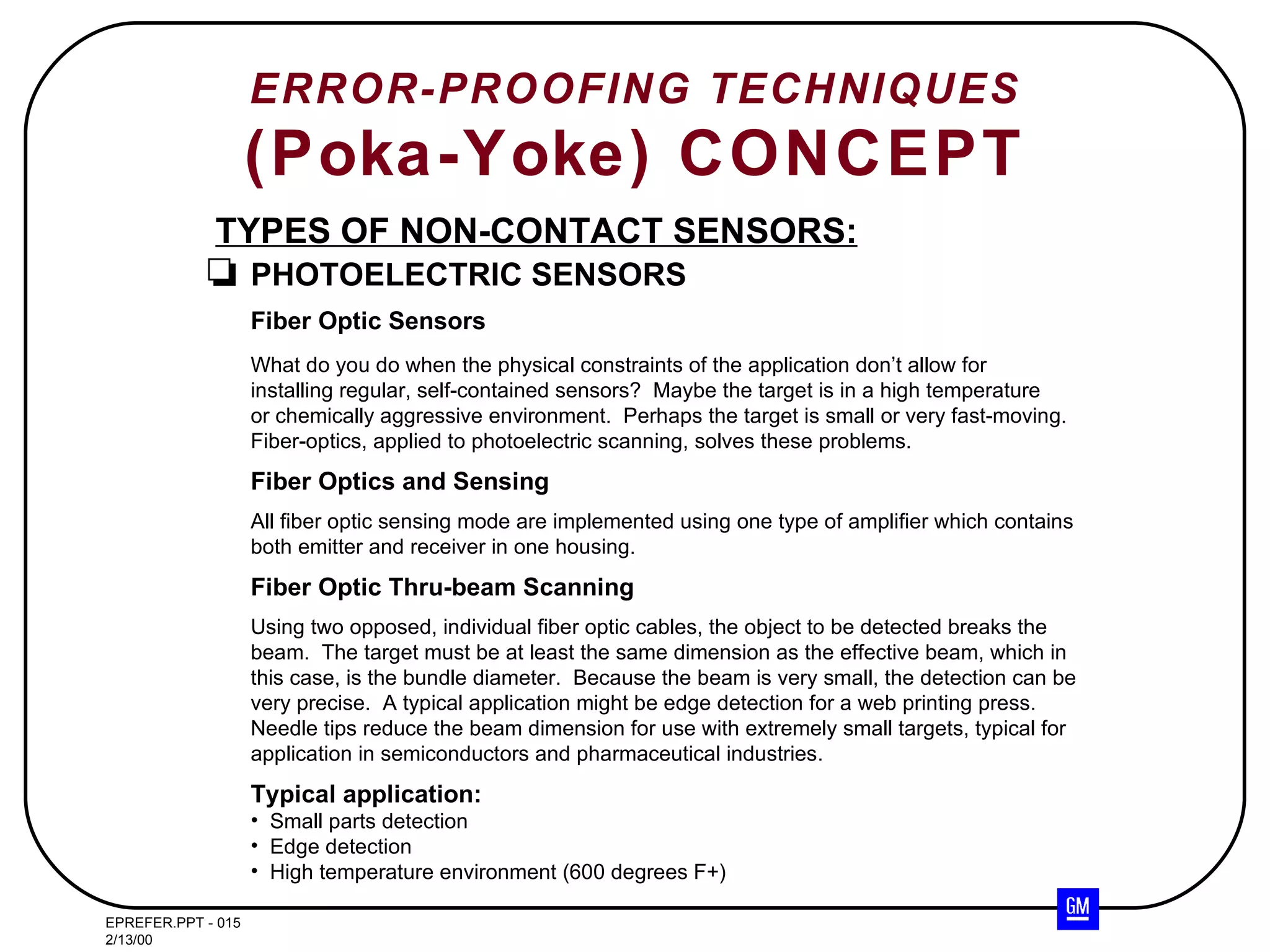
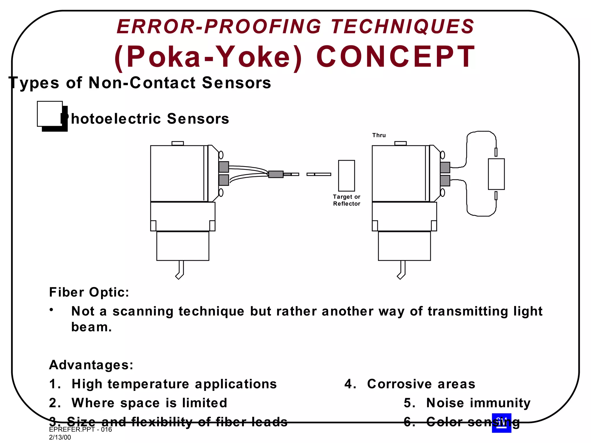
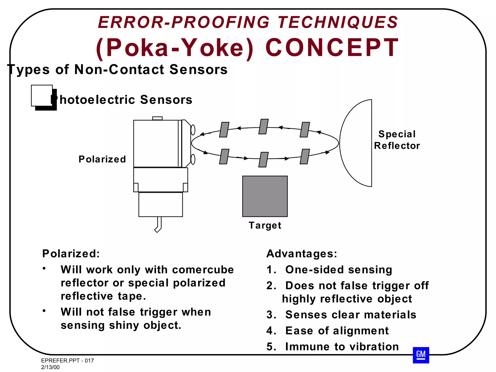
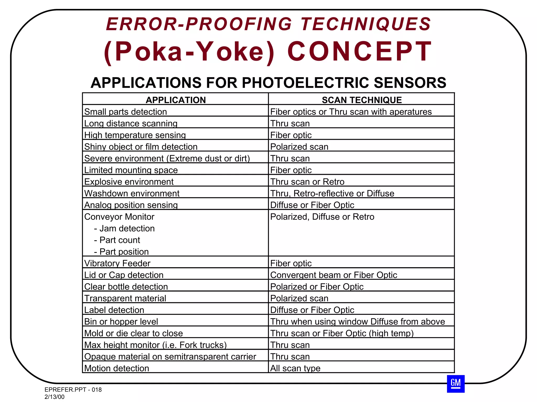
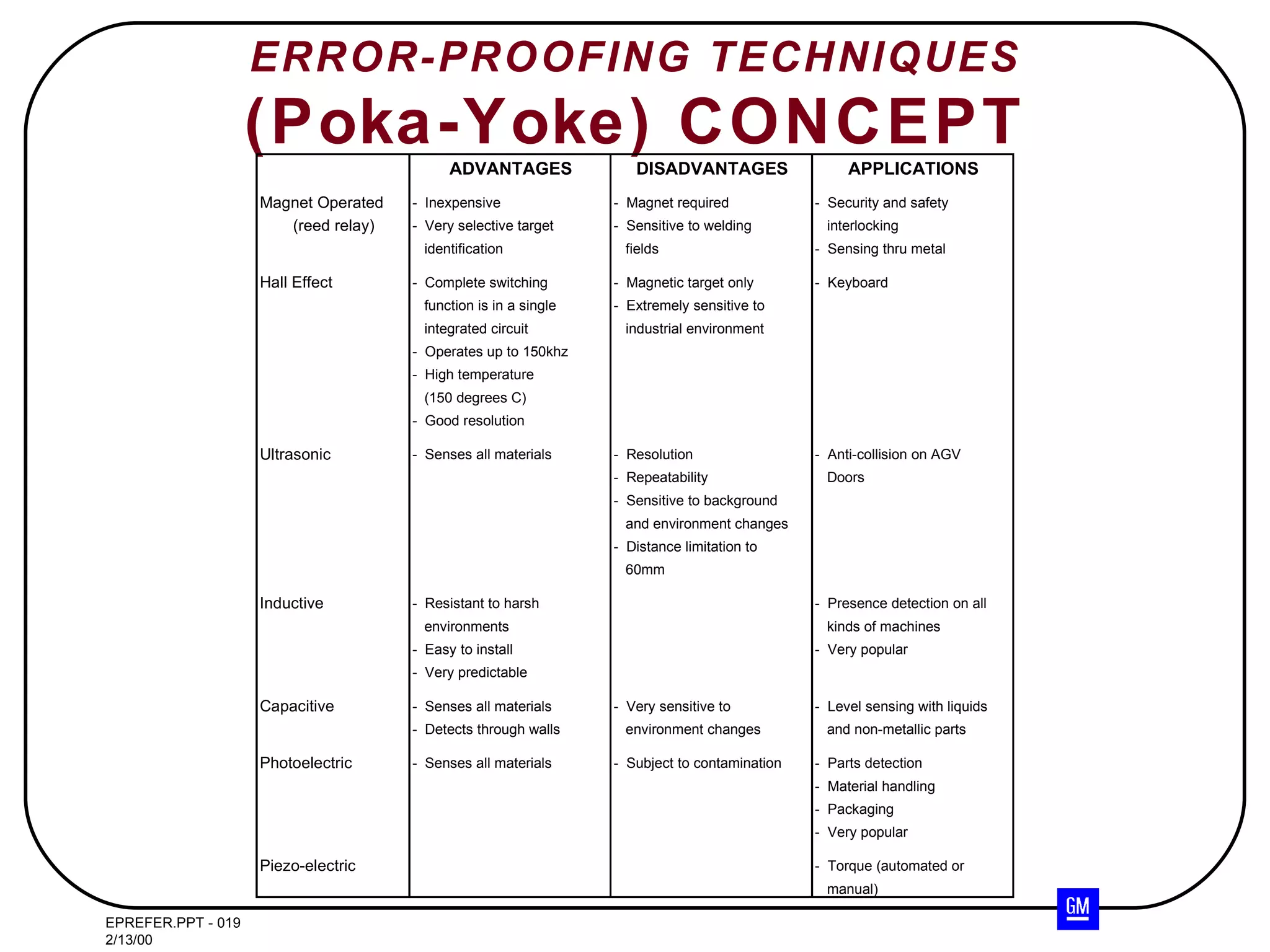
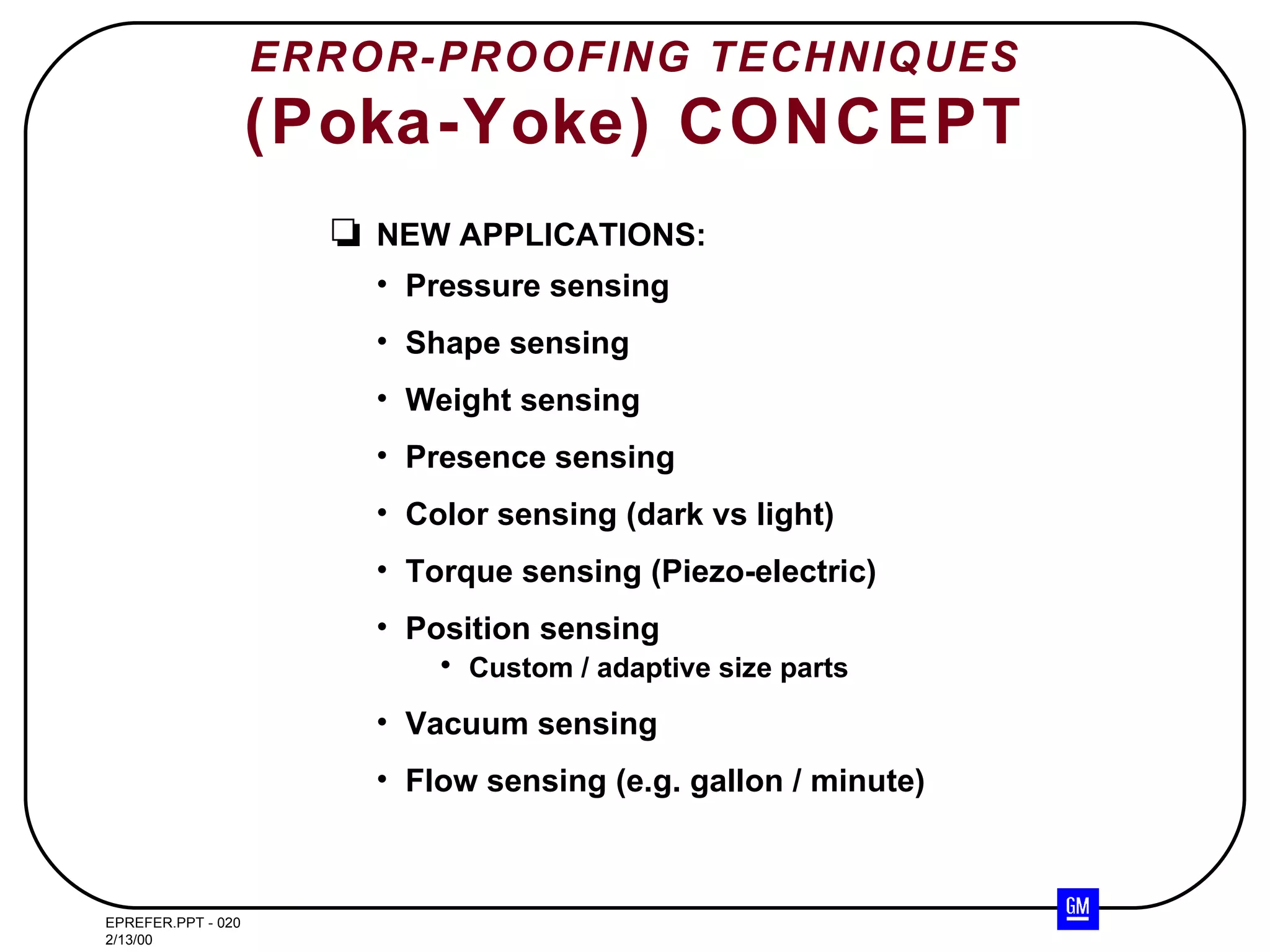
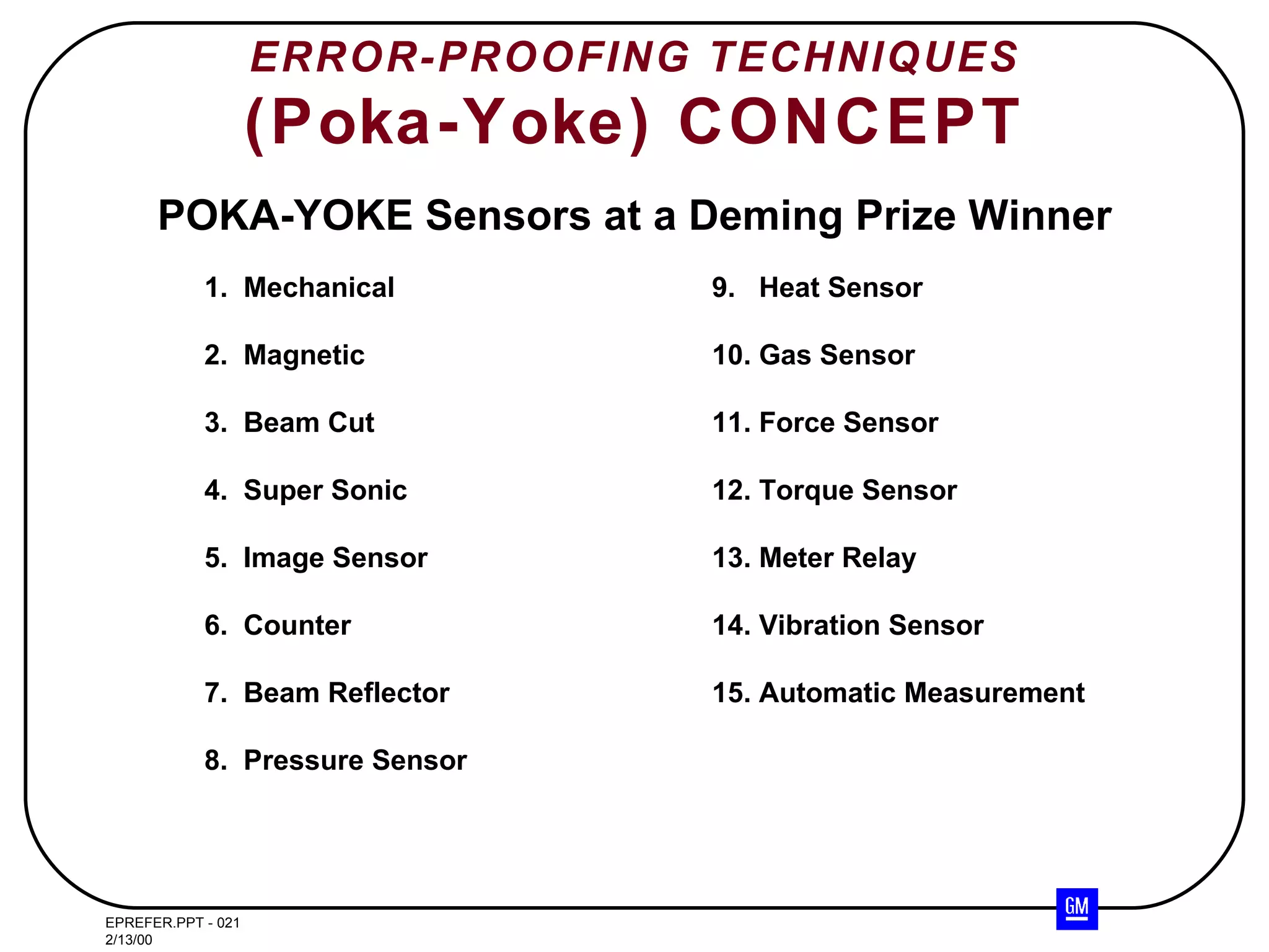

The document discusses various types of sensors used for error-proofing techniques (Poka-Yoke), including: - Discrete and analog sensors - Presence sensors that require physical contact or are non-contact - Non-contact sensors like reed relays, inductive, capacitive, and photoelectric sensors It provides details on the advantages and applications of these different sensor types.


![PHOTO ELECTRIC SENSORS [Autosaved].pptx](https://cdn.slidesharecdn.com/ss_thumbnails/photoelectricsensorsautosaved-230122195642-139c3524-thumbnail.jpg?width=640&height=640&fit=bounds)


