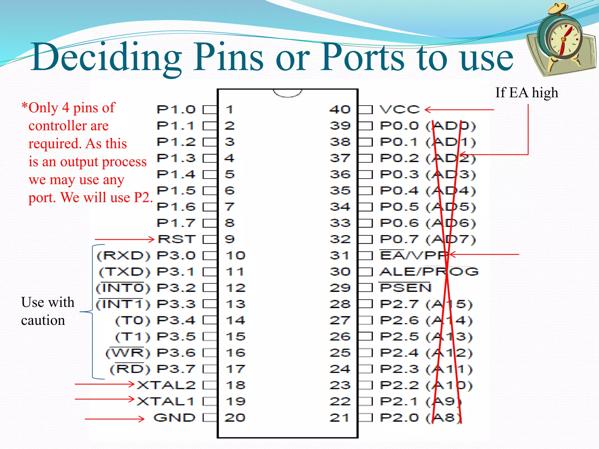
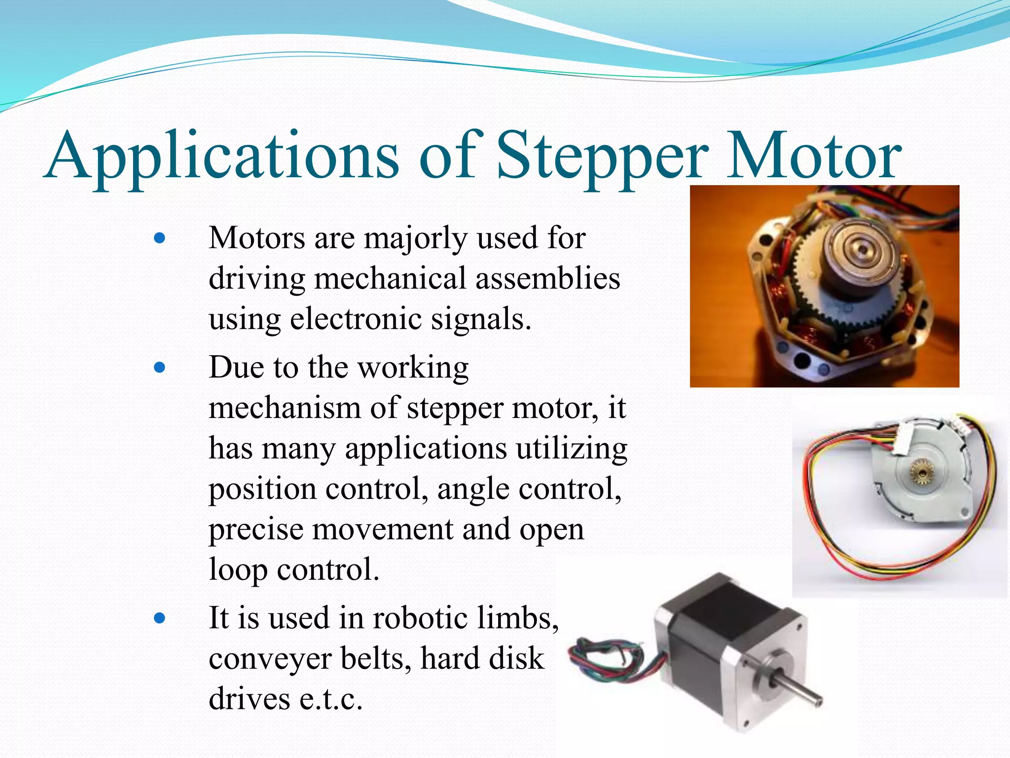
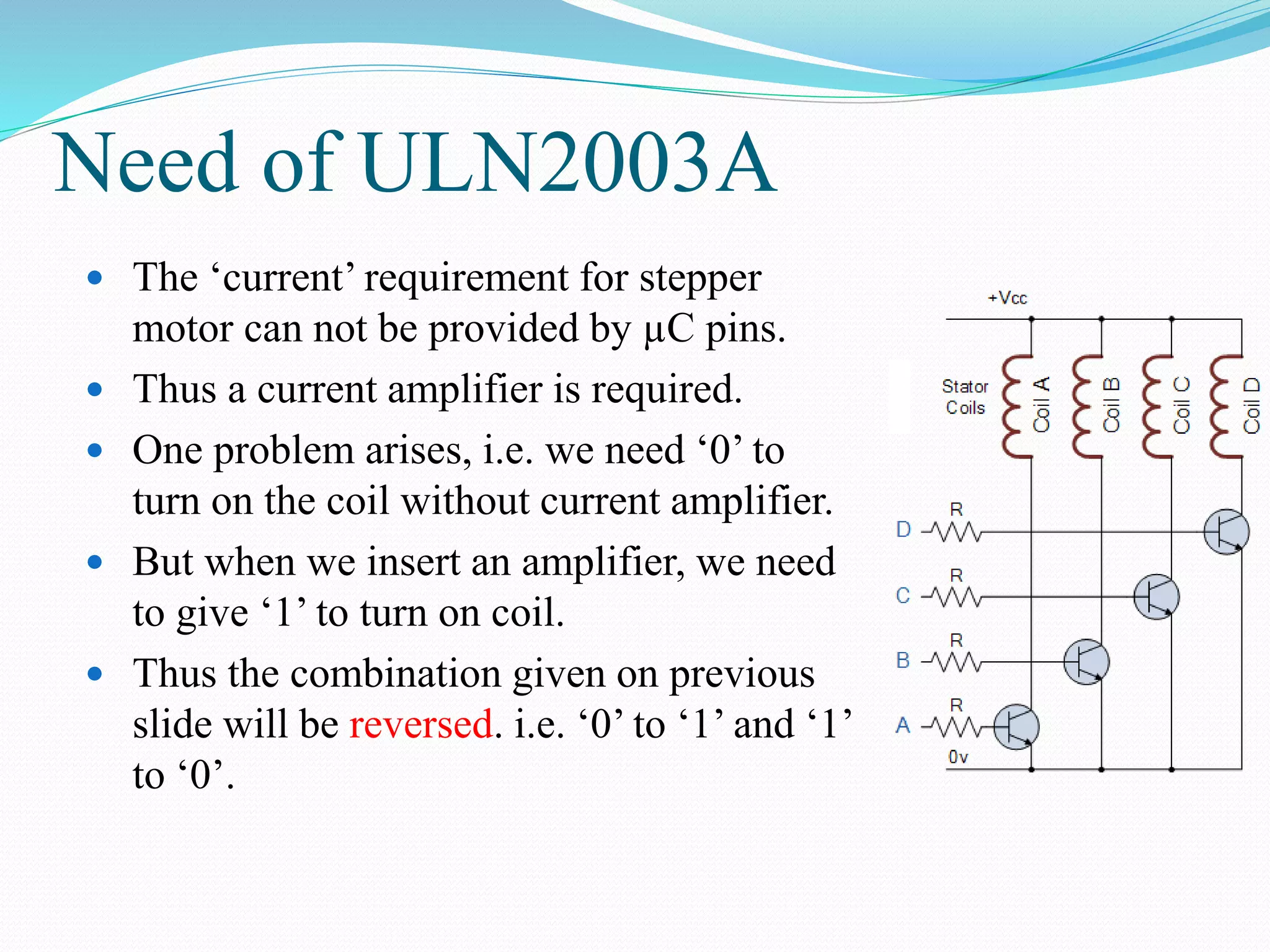
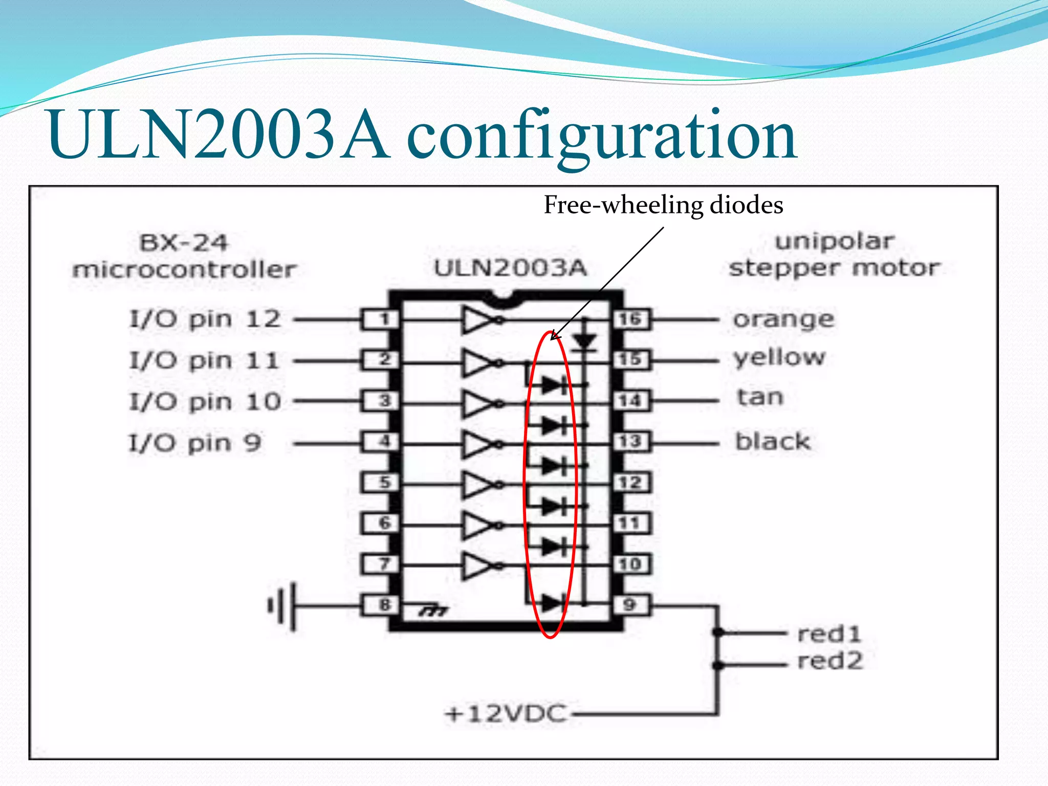
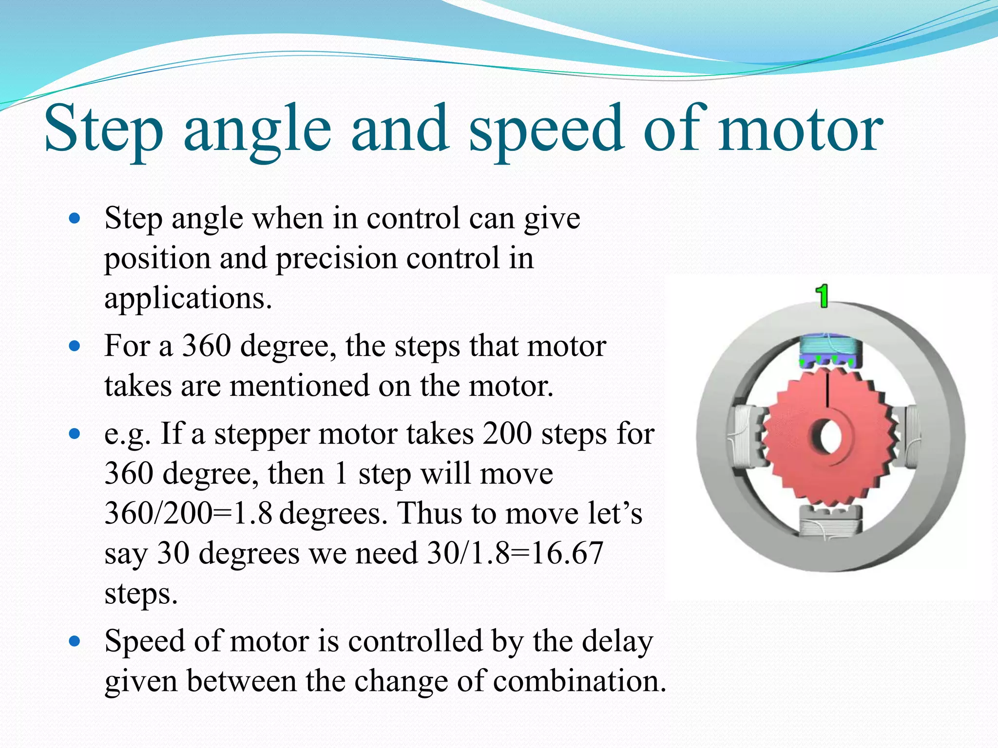
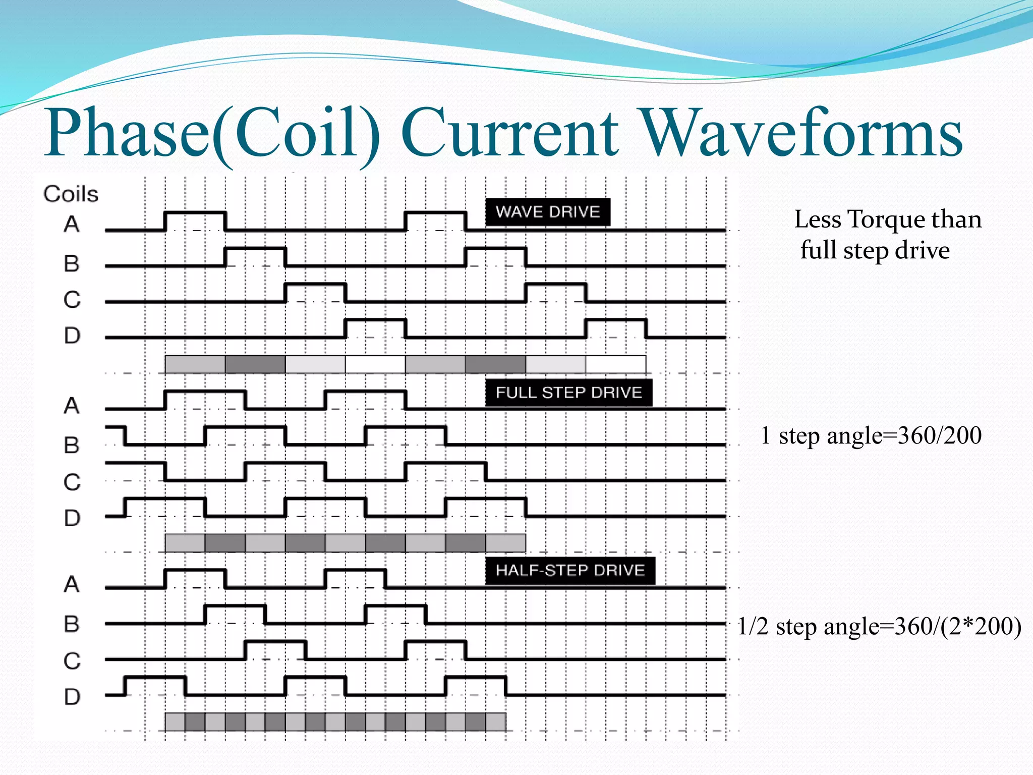
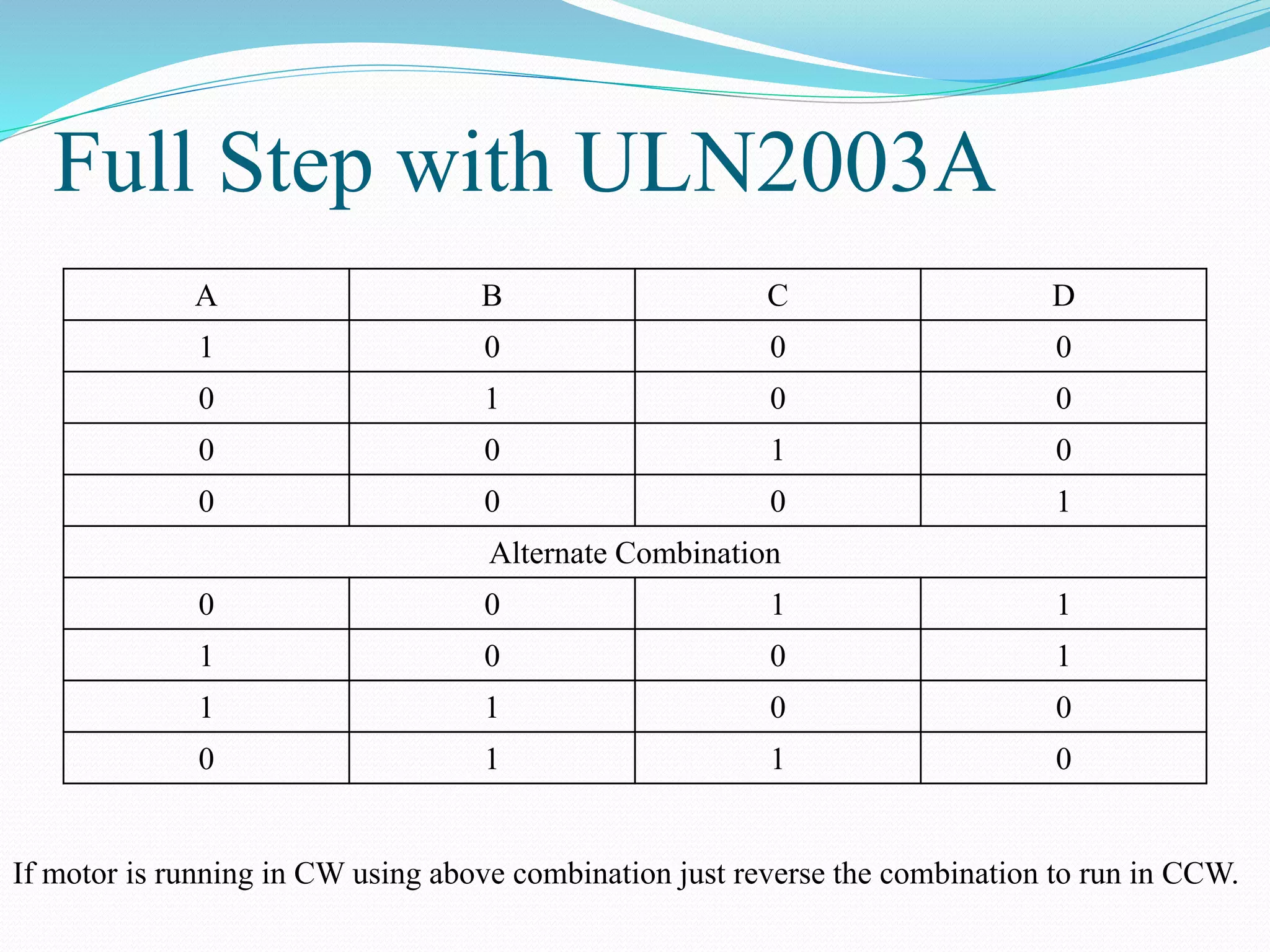
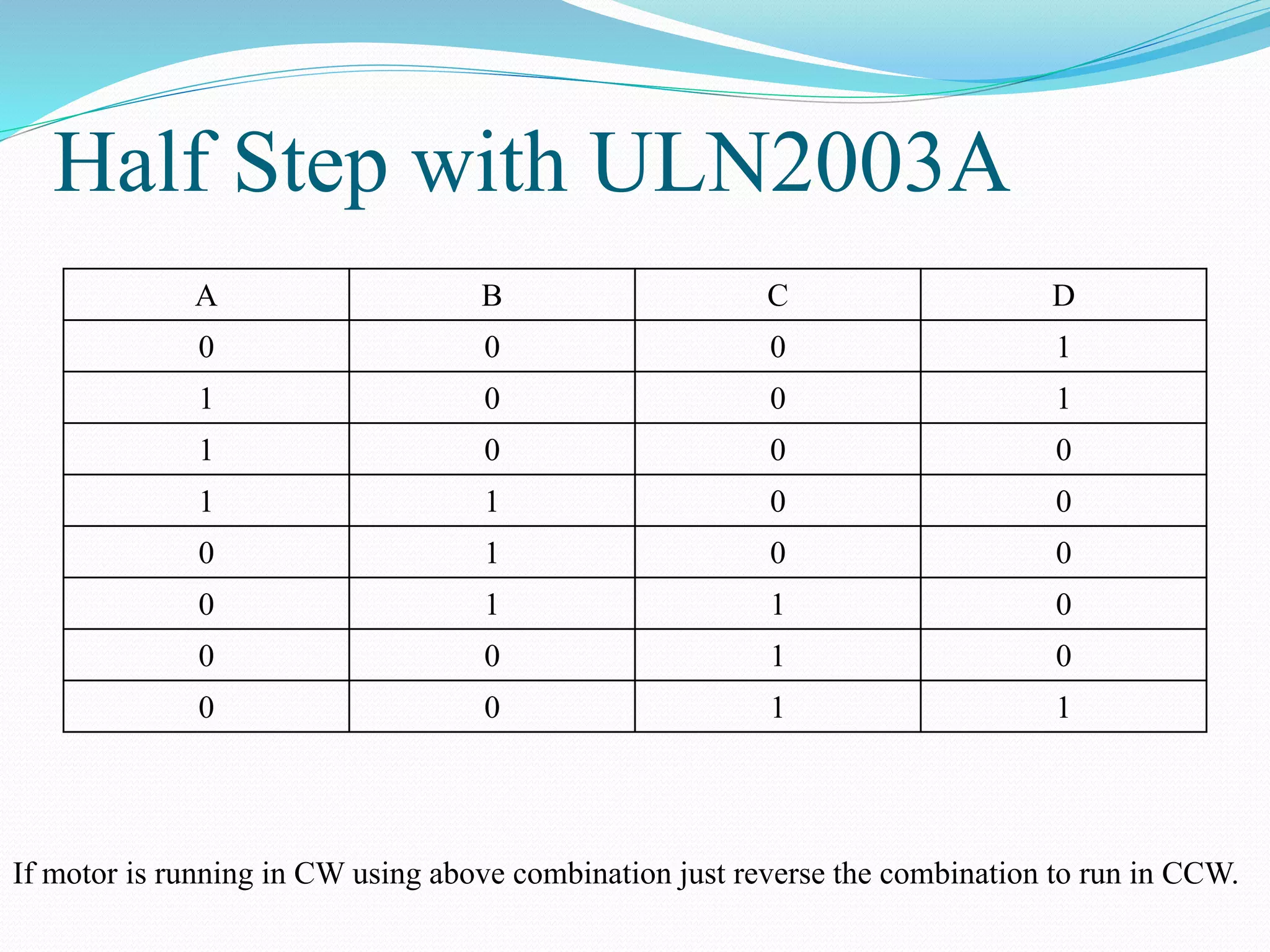
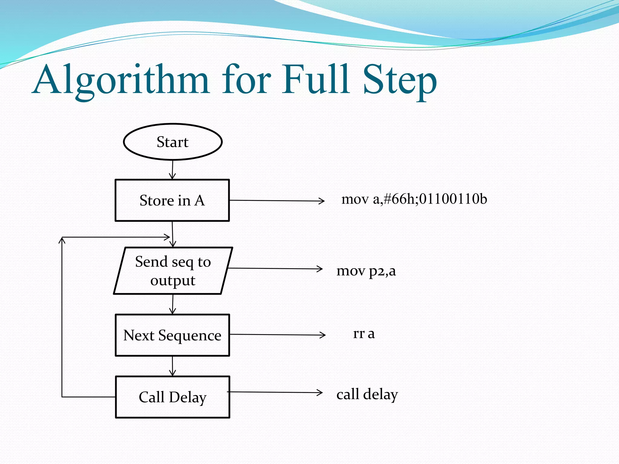
DRIVING STEPPER MOTOR USING 8051
Objectives of the Lab
 The Applications of Stepper Motor
 Learning how to find the wiring combination of stepper motor
 Learning how to run stepper motor CW or CCW
 About ULN2003 chip
 Interfacing stepper motor with 8051
Deciding Pins or Ports to use
Use with
caution
If EA high
*Only 4 pins of
controller are
required. As this
is an output process
we may use any
port. We will use P2.
Applications of Stepper Motor
 Motors are majorly used for
driving mechanical assemblies
using electronic signals.
 Due to the working
mechanism of stepper motor, it
has many applications utilizing
position control, angle control,
precise movement and open
loop control.
 It is used in robotic limbs,
conveyer belts, hard disk
drives e.t.c.
Theory of Operation
 This is best explained using figures.
Wiring of Stepper Motor
 We can find stepper motor configuration
by first finding the common pins.
 See the entities where R is there, the pin
that is common will be ‘common’.
 Now, we give 12V to the common pins,
and give one by one ground on other pins.
12 13 14 15 16 23 24 25 26
R 2R OL OL OL R OL OL OL
34 35 36 45 46 56
OL OL OL R 2R R
Wiring of Stepper Motor (contd.)
 When we give ground on one-pin, the
stepper motor makes a step to either CW
or CCW.
 We need to give ground one-by-one to the
pins and adjust them in the sequence such
as when ground one-by-one is given to the
pins, the motor should move CW or CCW.
 Remember this combination and mark the
pins as ABCD.
 Now, we see that when we give ABCD
0111, 1011, 1101 & 1110, the motor
moves CW or CCW.
Stepper Motor combinations
A B C D
0 1 1 1
1 0 1 1
1 1 0 1
1 1 1 0
Alternate Combination
1 1 0 0
0 1 1 0
0 0 1 1
1 0 0 1
If motor is running in CW using above combination just reverse the combination to run in CCW.
Need of ULN2003A
 The ‘current’ requirement for stepper
motor can not be provided by µC pins.
 Thus a current amplifier is required.
 One problem arises, i.e. we need ‘0’ to
turn on the coil without current amplifier.
 But when we insert an amplifier, we need
to give ‘1’ to turn on coil.
 Thus the combination given on previous
slide will be reversed. i.e. ‘0’ to ‘1’ and ‘1’
to ‘0’.
ULN2003A configuration
Free-wheeling diodes
Step angle and speed of motor
 Step angle when in control can give
position and precision control in
applications.
 For a 360 degree, the steps that motor
takes are mentioned on the motor.
 e.g. If a stepper motor takes 200 steps for
360 degree, then 1 step will move
360/200=1.8 degrees. Thus to move let’s
say 30 degrees we need 30/1.8=16.67
steps.
 Speed of motor is controlled by the delay
given between the change of combination.
Phase(Coil) Current Waveforms
Less Torque than
full step drive
1 step angle=360/200
1/2 step angle=360/(2*200)
Full Step with ULN2003A
A B C D
1 0 0 0
0 1 0 0
0 0 1 0
0 0 0 1
Alternate Combination
0 0 1 1
1 0 0 1
1 1 0 0
0 1 1 0
If motor is running in CW using above combination just reverse the combination to run in CCW.
Half Step with ULN2003A
A B C D
0 0 0 1
1 0 0 1
1 0 0 0
1 1 0 0
0 1 0 0
0 1 1 0
0 0 1 0
0 0 1 1
If motor is running in CW using above combination just reverse the combination to run in CCW.
Algorithm for Full Step
Start
Send seq to
output
Store in A
Next Sequence
Call Delay
mov a,#66h;01100110b
mov p2,a
rr a
call delay
Proteus Devices needed in this Lab
1. AT89c51
2. ULN2003A
3. Stepper Motor
Lab Tasks
 Run Stepper Motor using 8051.

Micro c lab5(stepper-motor)

  • 1.
  • 2.
    Objectives of theLab  The Applications of Stepper Motor  Learning how to find the wiring combination of stepper motor  Learning how to run stepper motor CW or CCW  About ULN2003 chip  Interfacing stepper motor with 8051
  • 3.
    Deciding Pins orPorts to use Use with caution If EA high *Only 4 pins of controller are required. As this is an output process we may use any port. We will use P2.
  • 4.
    Applications of StepperMotor  Motors are majorly used for driving mechanical assemblies using electronic signals.  Due to the working mechanism of stepper motor, it has many applications utilizing position control, angle control, precise movement and open loop control.  It is used in robotic limbs, conveyer belts, hard disk drives e.t.c.
  • 5.
    Theory of Operation This is best explained using figures.
  • 6.
    Wiring of StepperMotor  We can find stepper motor configuration by first finding the common pins.  See the entities where R is there, the pin that is common will be ‘common’.  Now, we give 12V to the common pins, and give one by one ground on other pins. 12 13 14 15 16 23 24 25 26 R 2R OL OL OL R OL OL OL 34 35 36 45 46 56 OL OL OL R 2R R
  • 7.
    Wiring of StepperMotor (contd.)  When we give ground on one-pin, the stepper motor makes a step to either CW or CCW.  We need to give ground one-by-one to the pins and adjust them in the sequence such as when ground one-by-one is given to the pins, the motor should move CW or CCW.  Remember this combination and mark the pins as ABCD.  Now, we see that when we give ABCD 0111, 1011, 1101 & 1110, the motor moves CW or CCW.
  • 8.
    Stepper Motor combinations AB C D 0 1 1 1 1 0 1 1 1 1 0 1 1 1 1 0 Alternate Combination 1 1 0 0 0 1 1 0 0 0 1 1 1 0 0 1 If motor is running in CW using above combination just reverse the combination to run in CCW.
  • 9.
    Need of ULN2003A The ‘current’ requirement for stepper motor can not be provided by µC pins.  Thus a current amplifier is required.  One problem arises, i.e. we need ‘0’ to turn on the coil without current amplifier.  But when we insert an amplifier, we need to give ‘1’ to turn on coil.  Thus the combination given on previous slide will be reversed. i.e. ‘0’ to ‘1’ and ‘1’ to ‘0’.
  • 10.
  • 11.
    Step angle andspeed of motor  Step angle when in control can give position and precision control in applications.  For a 360 degree, the steps that motor takes are mentioned on the motor.  e.g. If a stepper motor takes 200 steps for 360 degree, then 1 step will move 360/200=1.8 degrees. Thus to move let’s say 30 degrees we need 30/1.8=16.67 steps.  Speed of motor is controlled by the delay given between the change of combination.
  • 12.
    Phase(Coil) Current Waveforms LessTorque than full step drive 1 step angle=360/200 1/2 step angle=360/(2*200)
  • 13.
    Full Step withULN2003A A B C D 1 0 0 0 0 1 0 0 0 0 1 0 0 0 0 1 Alternate Combination 0 0 1 1 1 0 0 1 1 1 0 0 0 1 1 0 If motor is running in CW using above combination just reverse the combination to run in CCW.
  • 14.
    Half Step withULN2003A A B C D 0 0 0 1 1 0 0 1 1 0 0 0 1 1 0 0 0 1 0 0 0 1 1 0 0 0 1 0 0 0 1 1 If motor is running in CW using above combination just reverse the combination to run in CCW.
  • 15.
    Algorithm for FullStep Start Send seq to output Store in A Next Sequence Call Delay mov a,#66h;01100110b mov p2,a rr a call delay
  • 16.
    Proteus Devices neededin this Lab 1. AT89c51 2. ULN2003A 3. Stepper Motor
  • 17.
    Lab Tasks  RunStepper Motor using 8051.