What is astepper motor?
• A motor, in general, is a device that converts electrical energy into
mechanical energy.
• As the name suggests, a stepper motor is a device that does the same
task as above but, in steps.
• It is a brushless, synchronous electric motor that can divide a
complete rotation into a number of steps. Stepper motors generally
have a permanent magnet shaft (rotor), and it is surrounded by a
stator.
3.
• The bestfeature of this type of motor is that the motor’s angular
position can be accurately controlled without any feedback
mechanism, as long as the motor is not oversized. (From a designer’s
point of view the sizing of the motor is essential, if the stepper motor
is undersized then it will not be able to withstand load and if it is
oversized then it becomes too expensive for its purpose.).
• Therefore, it works in a simple accurate open-loop system, where the
output is directly dependent on the input.
4.
Step angle :
•A stepper motor rotates at small angles to complete 360 degrees
rotation these small angles are called steps, hence the name Stepper
Motor. Typically, a stepper motor consists of 200 steps.
• 200 Steps = 360 degrees
1 Step = ‘x’ degrees
x = 360 / 200 = 1.8 degree
• Therefore, every step is 1.8 degrees.
5.
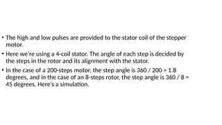
• The highand low pulses are provided to the stator coil of the stepper
motor.
• Here we’re using a 4-coil stator. The angle of each step is decided by
the steps in the rotor and its alignment with the stator.
• In the case of a 200-steps motor, the step angle is 360 / 200 = 1.8
degrees, and in the case of an 8-steps rotor, the step angle is 360 / 8 =
45 degrees. Here’s a simulation.
6.
Important terminology relatedto a stepper
motor
• Revolutions Per Minute (RPM): This term is often used when the
number of rotations is to be found per minute. It determines the
frequency with which the motor is rotating.
• Step Angle: Since a stepper motor rotates one step at a time, the
angle it sweeps in one step is called the Step Angle. For a rotor having
200 steps/teeth, it is equal to 1.8 degrees and for a motor having 4
steps, it is equal to 90 degrees.
7.
• Steps perrevolution: This parameter decides the number of steps
required to complete one revolution and is determined by 360 / (Step
Angle).
• Steps per second: As suggested by the name it determines the steps
covered in one second and is given by
• Steps per second = RPM x steps per revolution / 60
8.
Type of StepperMotor
• Stepper motors are broadly classified into two types
1. Unipolar stepper motor
2. Bipolar stepper motor
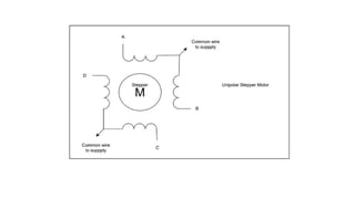
1.Unipolar stepper motor
• The unipolar stepper motor has five or six wires out of which four wires are
joined to one of the ends of each of the four stator coils. The connections at the
center of the coils are joined together and are connected to the 12V supply. They
are called unipolar steppers because power always comes in on this one pole.
10.
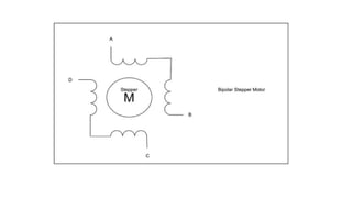
Bipolar stepper motor
•The bipolar stepper motor usually has four wires coming out of it.
Unlike unipolar steppers, bipolar steppers have no common center
connection. They have two independent sets of coils instead.
• We’re going to use the unipolar stepper motor in our further
discussions since it is easier to operate, widely available, and usually
the cheapest means to get precise angular moments.
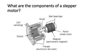
1. Stator: Thestator is made up of four coils, that are energized by the
pulses from a microcontroller or a stepper controller.
2. Rotor: The number of steps of the rotor and its alignment with the
stator determines the step angle and steps per revolution.
3. Permanent magnets: The rotor is mounted on a permanent magnet
that attracts or repels the stator coils and hence the propulsion
occurs.
14.
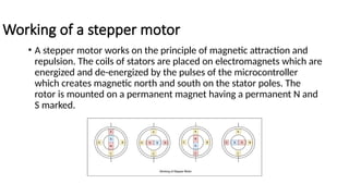
Working of astepper motor
• A stepper motor works on the principle of magnetic attraction and
repulsion. The coils of stators are placed on electromagnets which are
energized and de-energized by the pulses of the microcontroller
which creates magnetic north and south on the stator poles. The
rotor is mounted on a permanent magnet having a permanent N and
S marked.
15.
The sequence inwhich the coils are excited to form the poles causes the
rotor to attract one pair of stator pole and repel the other causing
motion in the shaft and the load connected to it.
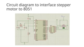
Interfacing stepper motor to 8051 Microcontroller
• We are using Port 2 of 8051 microcontroller to generate high and low
pulses and using a current amplifier IC i.e. ULN2003a to amplify the
current to drive the stepper motor using the pulse of the
microcontroller.
16.
• On thebasis of the way the coils are energized, a Unipolar Stepper
motor can be classified into three categories:
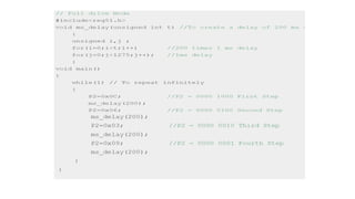
1.Wave Drive Mode
2.Full Drive Mode
3.Half Drive Mode
17.
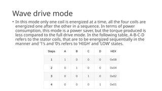
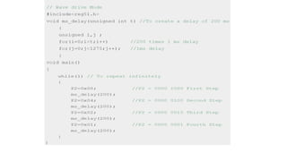
Wave drive mode
•In this mode only one coil is energized at a time, all the four coils are
energized one after the other in a sequence. In terms of power
consumption, this mode is a power saver, but the torque produced is
less compared to the full drive mode. In the following table, A-B-C-D
refers to the stator coils, that are to be energized sequentially in the
manner and ‘1’s and ‘0’s refers to ‘HIGH‘ and ‘LOW’ states.
18.
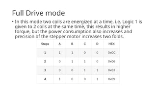
Full Drive mode
•In this mode two coils are energized at a time, i.e. Logic 1 is
given to 2 coils at the same time, this results in higher
torque, but the power consumption also increases and
precision of the stepper motor increases two folds.
19.
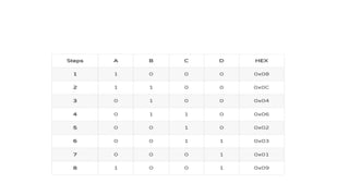
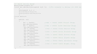
Half Drive Mode
•This mode works on the alternate energizing principle, i.e. at
one moment only 1 coil is energized, but in the very next
moment 2 coils are energized, then again back to 1. This
sequence is repeated so as to make the motor more power-
efficient while maintaining the high torque and increase the
angular rotation of the motor.
21.
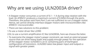
Why are weusing ULN2003A driver?
• A Stepper motor consumes a current of 0.1 – 1 A during step rotation with the
load. An AT89c51 produces a maximum current of 0.045A through the ports.
Therefore, the pulses sent from Port 2 are not sufficient to run a stepper motor.
Hence, we cannot directly interface stepper motors with microcontrollers like
AT89C51 microcontroller.
• There are two solutions to this problem:
1.To use a motor driver like L239D
2.Or, to use a current amplification IC like ULN2003A, here we choose the latter.
• To overcome the stepper motor’s power constraint, we need an external power
source that can drive heavy loads and supply enough power for the operation
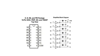
of the stepper motor. ULN2003 is an IC containing pairs of Darlington
configuration of transistors. ULN2003 takes low power input and outputs a
signal with greater power.
Applications of steppermotors
• Used in Dot Matrix Printer.
• Used in tape drives, floppy disc drives, printers, and electric watches.
• Metal cutting & Metal forming machines.
• Used in textile industries.
• Used in integrated circuits fabrications.