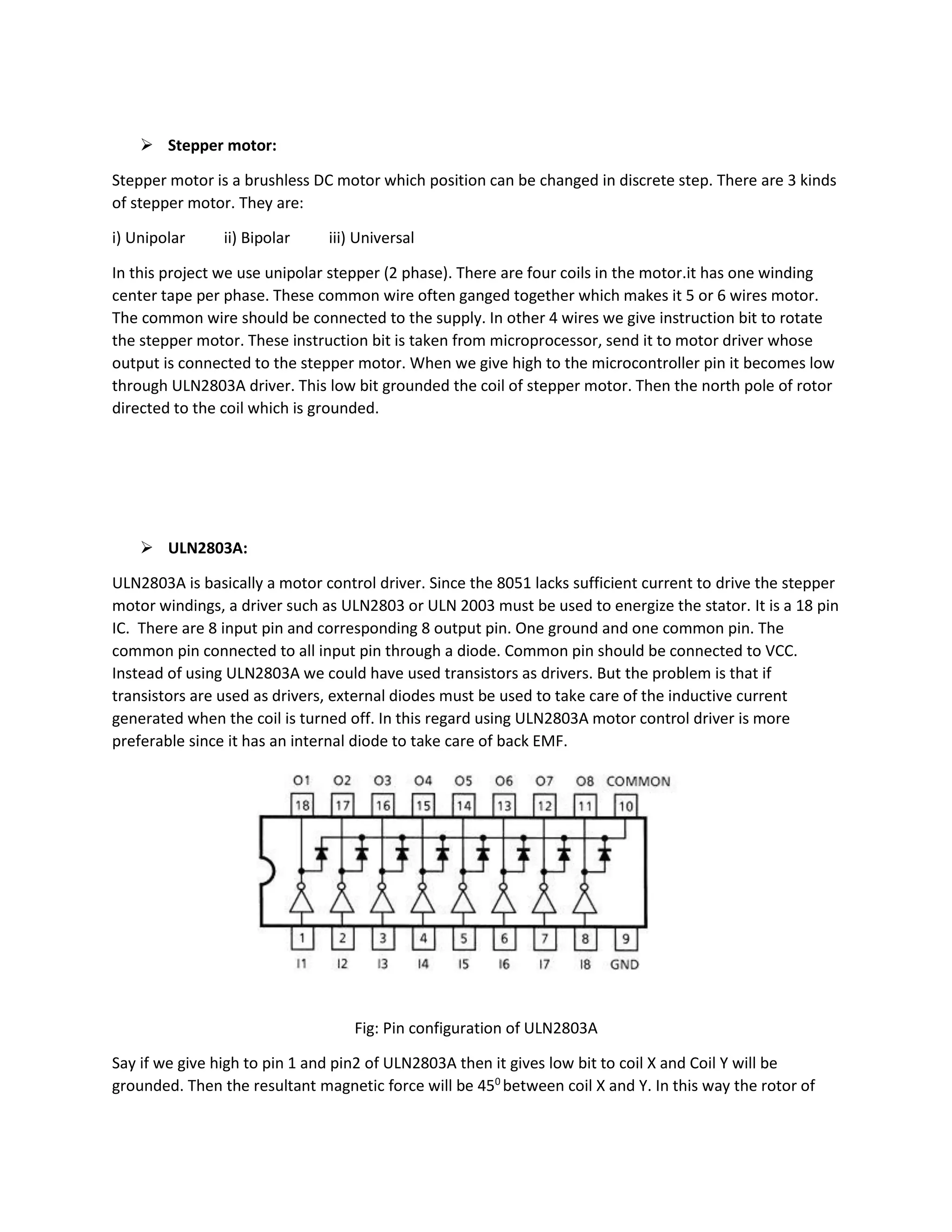
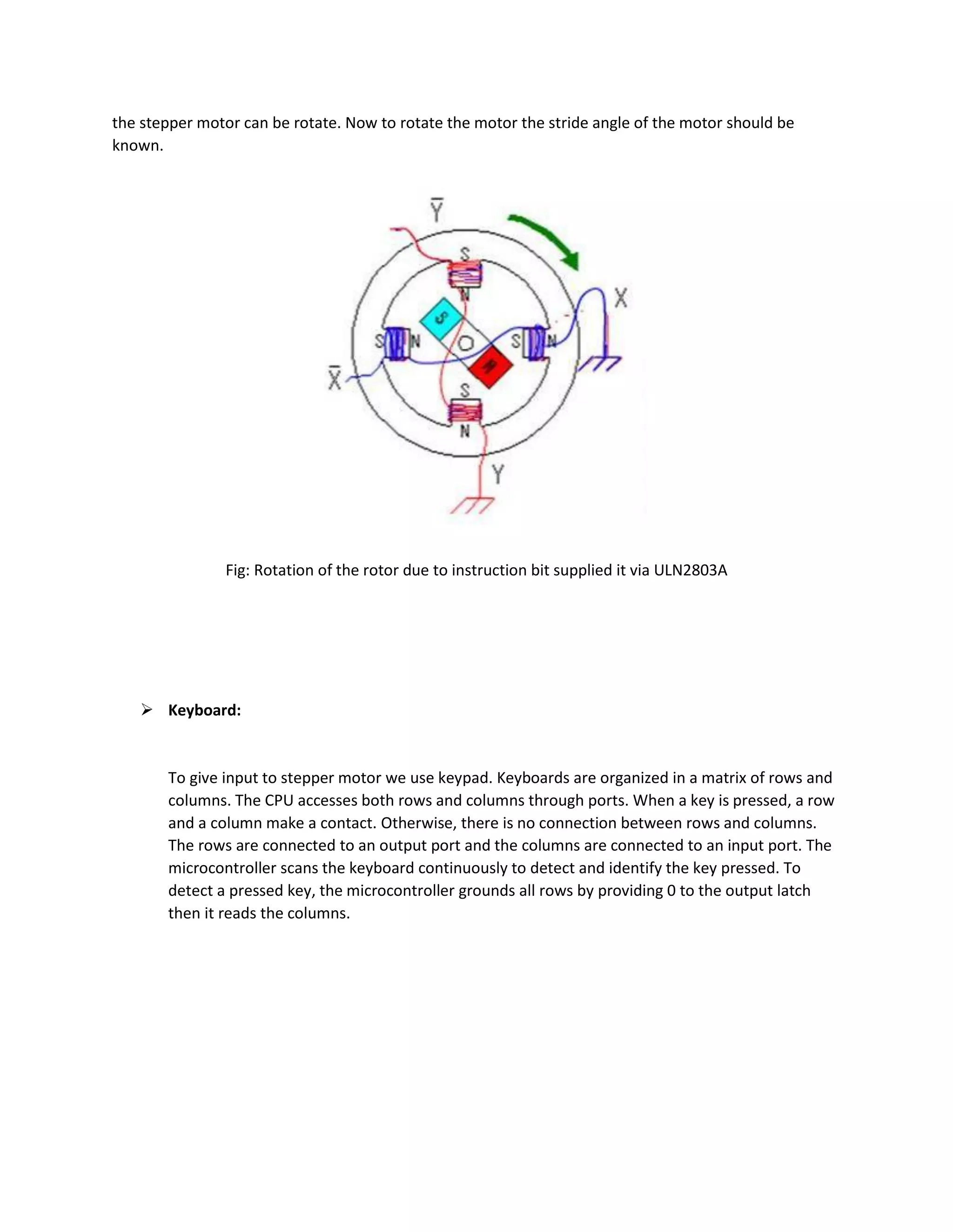
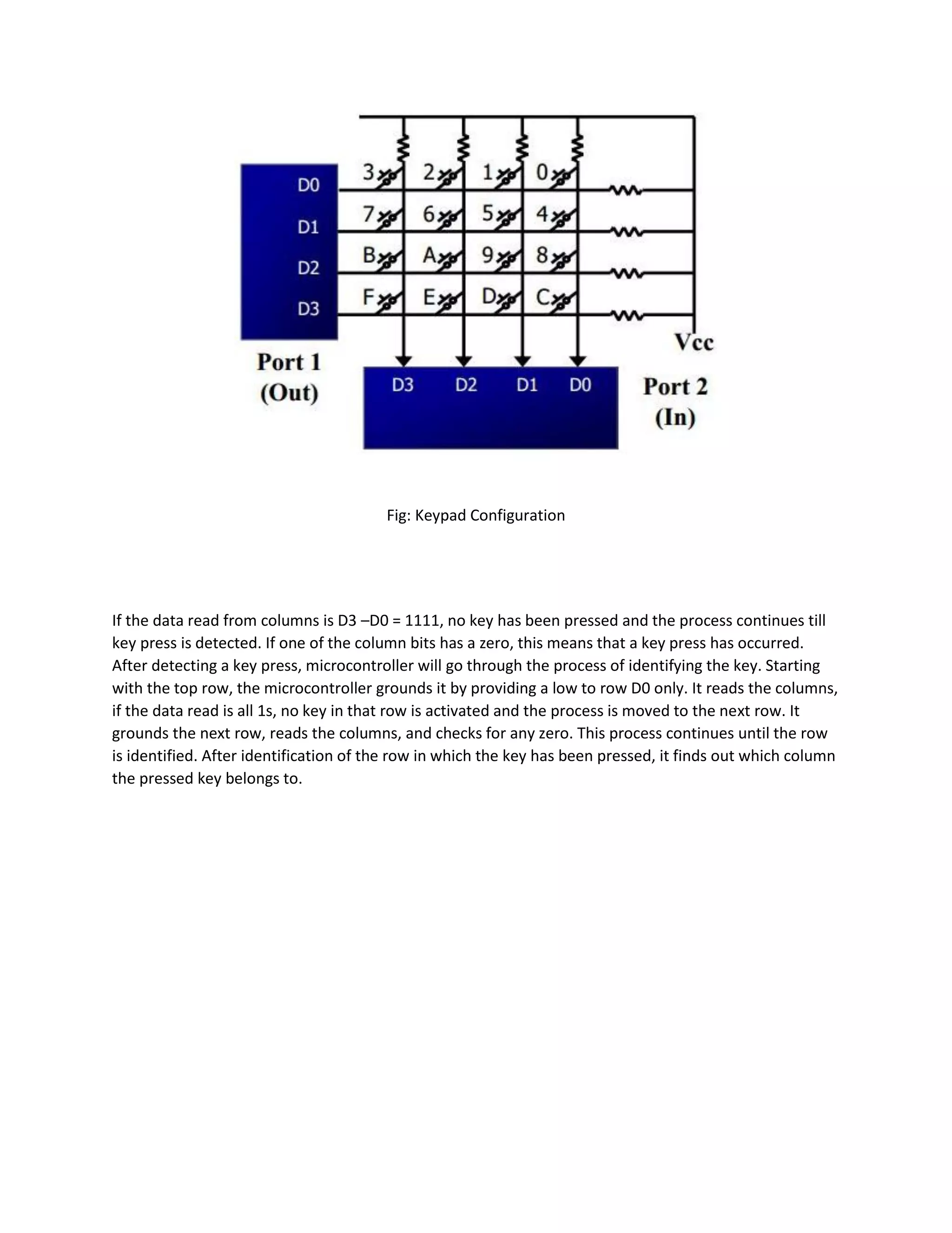
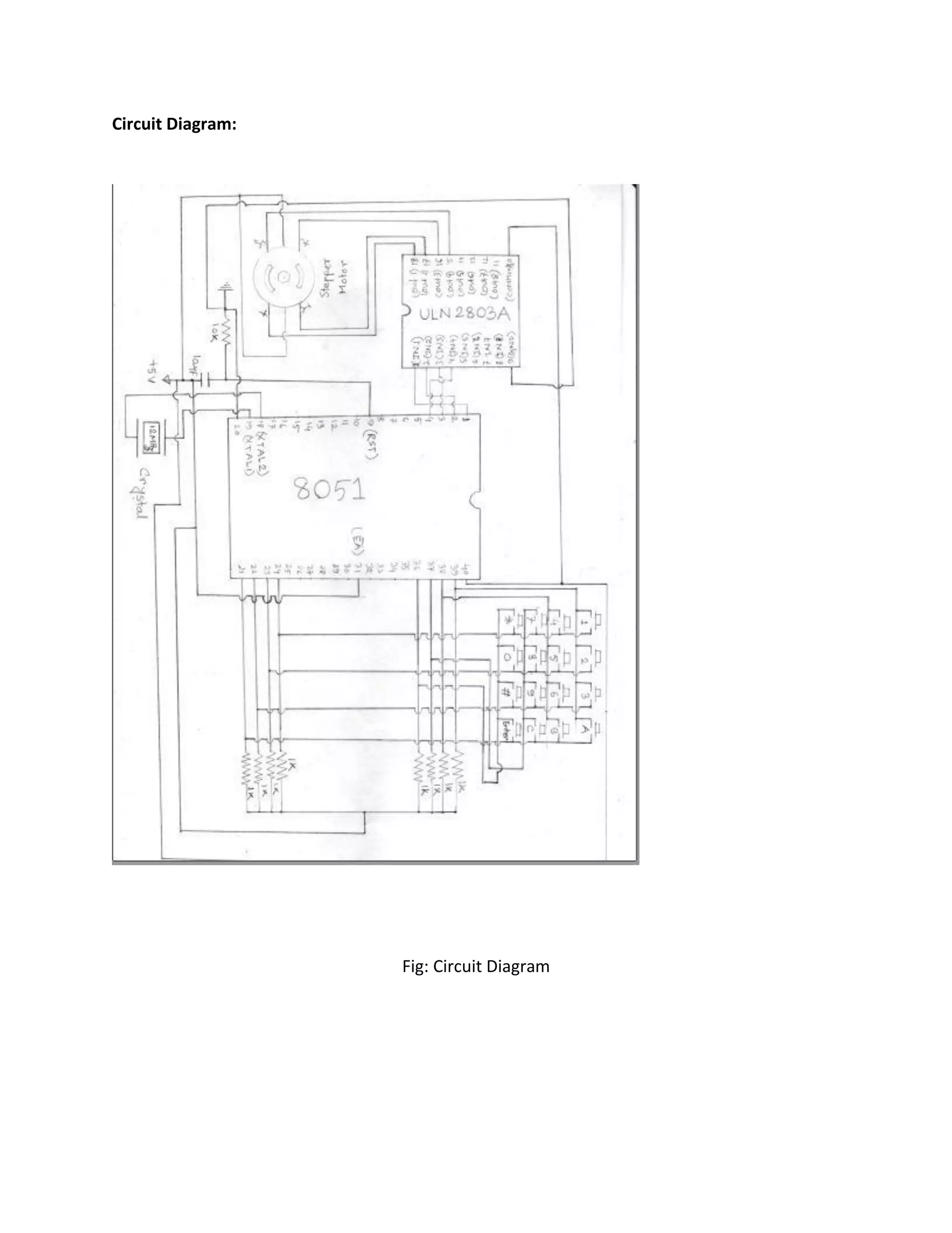
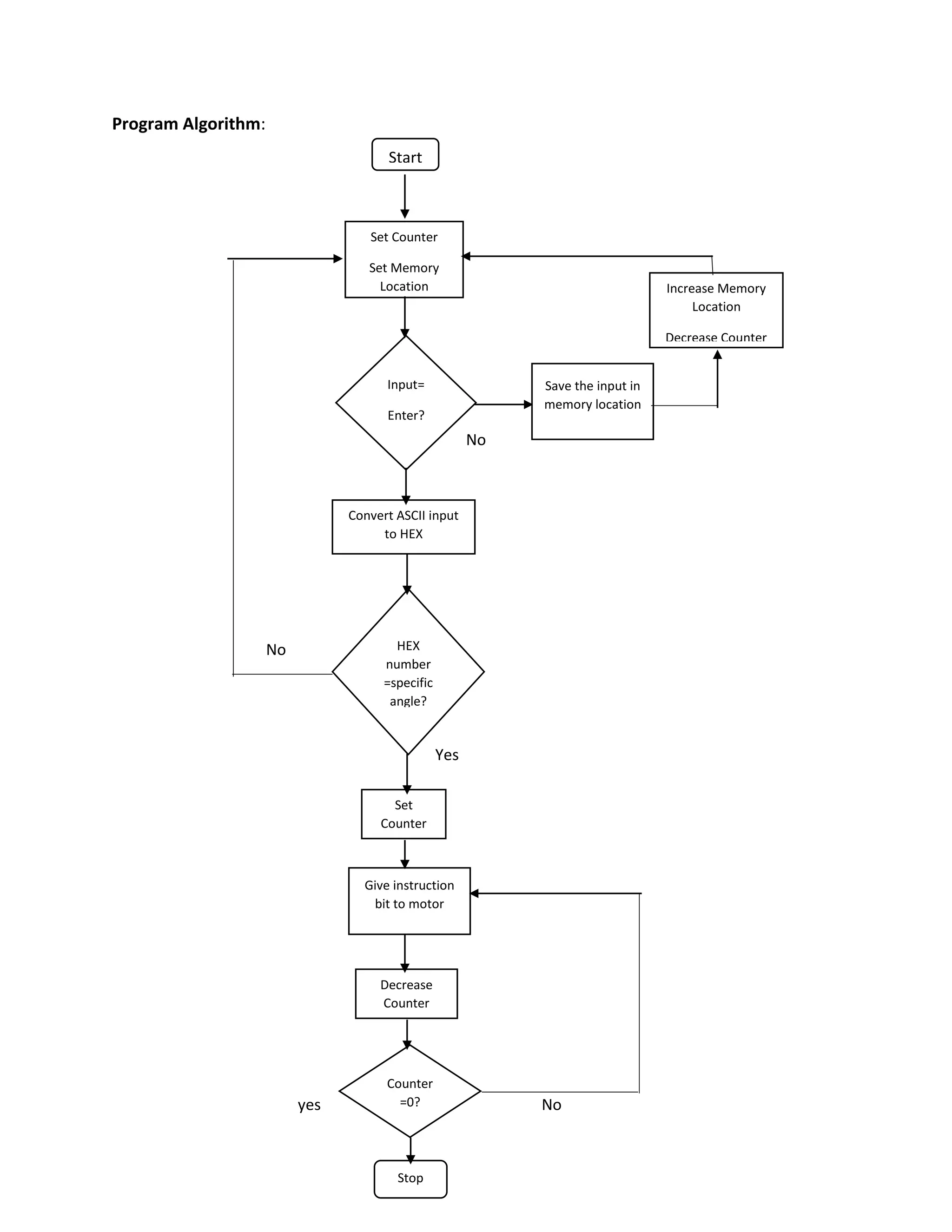
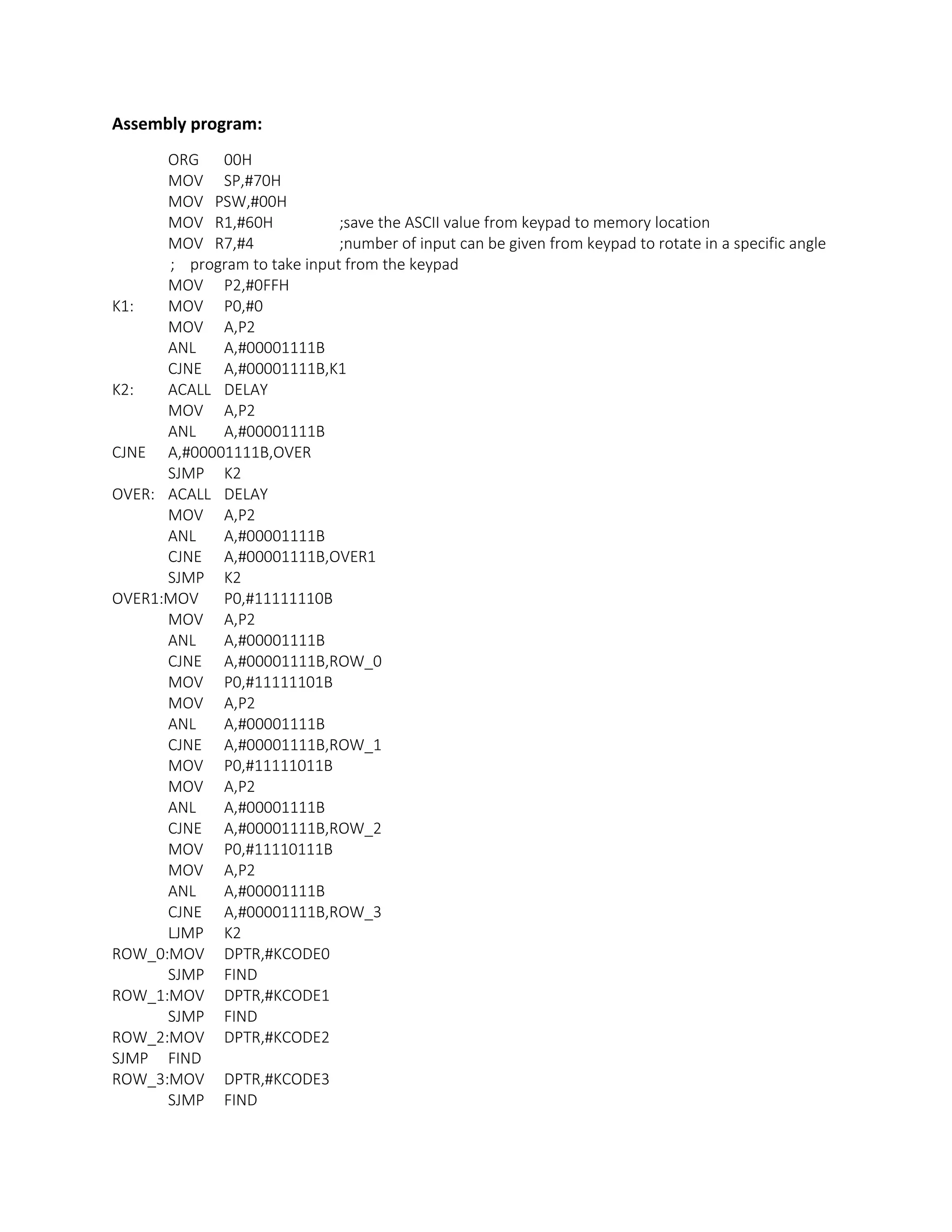
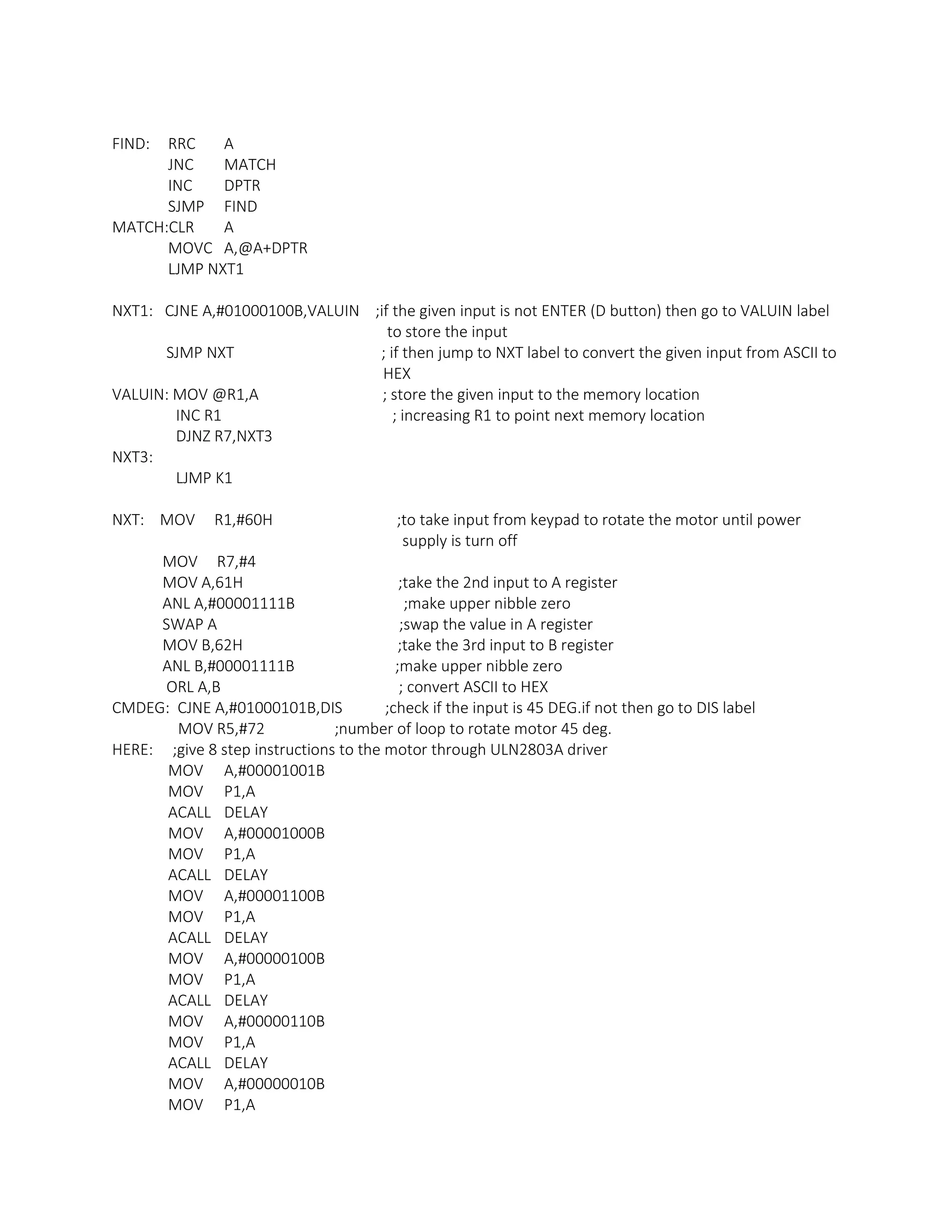
The document describes a project to control the rotation of a stepper motor to specific angles through a keypad input. The objective is to rotate the stepper motor 45, 90, 135, 180, 225, 270, and 315 degrees based on the input provided via the keypad. An AT89S52 microcontroller is used to read the keypad input and provide the appropriate signals to a ULN2803A driver, which drives the stepper motor coils to rotate it to the desired angle. The circuit diagram and assembly program code to implement the angle control are also included.
The document describes the basic processing unit of a computer. It discusses how a processor fetches and executes instructions through a series of steps. It explains the components involved, such as the program counter, instruction register, and arithmetic logic unit. It also covers different organizations for controlling instruction execution, including hardwired control and microprogrammed control using microinstructions and a control store.
Microchip's PIC Micro Controller - Presentation Covers- Embedded system,Application, Harvard and Von Newman Architecture, PIC Microcontroller Instruction Set, PIC assembly language programming, PIC Basic circuit design and its programming etc.
Pipelining is a technique where the instruction execution process is divided into multiple stages that can operate in parallel. This allows subsequent instructions to begin processing before previous ones have finished. For example, with laundry, pipelining allows washing, drying, and folding different loads simultaneously to complete all the laundry faster. In processors, pipelining overlaps the stages of instruction fetch, decode, execute, and writeback to improve throughput. While pipelining improves performance, it can introduce hazards like structural, data, and control hazards that must be addressed.
The document discusses the basic processing unit of a computer. It describes the objective, fundamental concepts, and components of a processor including the datapath, control unit, instruction cycle of fetch, decode, and execute. It explains the concepts of registers, arithmetic logic unit (ALU), and how instructions are executed through register transfers, arithmetic/logic operations, and reading/writing from memory. It also compares single-bus and multiple-bus processor organizations.
The document discusses various aspects of the ARM-7 architecture including its addressing modes, instruction set, and data processing instructions. It describes 9 different addressing modes including immediate, absolute, indirect, register, register indirect, base plus offset, base plus index, base plus scaled index, and stack addressing. It also provides details about the ARM instruction set, Thumb instruction set, and I/O system. Examples are given to illustrate different instructions such as MOV, SUB, ORR, CMP, MUL, branch instructions, LDR, STR, and SWI.
The document provides an overview of embedded operating systems. It discusses two general approaches: adapting an existing commercial OS or building a purpose-built OS. It then describes the embedded OS eCos, including its configurability, components, hardware abstraction layer, kernel, I/O system, and scheduler. Finally, it discusses the purpose-built OS TinyOS, including its goals for high concurrency, limited resources, hardware evolution, diverse applications and platforms, and robustness. It describes TinyOS' use of components, tasks, commands, events, and its shared resource configuration.
- Thumb is a 16-bit instruction set extension to the 32-bit ARM architecture that provides higher code density and smaller memory requirements compared to standard ARM code.
- Thumb instructions are 16-bits wide while ARM instructions are 32-bits wide, allowing Thumb code to be half the size of equivalent ARM code.
- Thumb code executes on ARM processors by decompressing Thumb instructions into their 32-bit ARM equivalents on the processor.
Interrupts are events that require immediate attention from the microcontroller. When an interrupt occurs, the microcontroller pauses its current task and executes an Interrupt Service Routine (ISR) to handle the interrupt. After the ISR finishes, the microcontroller returns to its previous task. For an interrupt to be handled, both the global interrupt enable bit and the specific interrupt's enable bit must be set. Each interrupt has an associated flag bit and enable bit, and a dedicated ISR. Interrupts can be internal, triggered by microcontroller peripherals, or external, triggered via pins.
hardwired control is the system level communication in which how the control signal generate by processor with the help of conditional codes, external output and counter circuits
The Trusted Platform Module (TPM) is an international standard for a secure cryptoprocessor developed by the Trusted Computing Group to provide hardware-based security related features. It measures the boot process and software running on a device to ensure integrity and allows for remote attestation of the device's state. The TPM provides roots of trust for measurement, reporting, and storage and utilizes platform configuration registers, sealed storage, and keys to securely store and report information based on the device's configuration.
The document discusses interrupts for the PIC18 microcontroller. It explains that interrupts allow the microcontroller to instantly respond to events like pin changes or timer overflows. When an interrupt occurs, the microcontroller stops executing the main program and jumps to the interrupt service routine (ISR) to handle the interrupt. It provides details on enabling and disabling interrupts, the interrupt vector table, and examples of using interrupts for external pins, timers, and serial communication.
Pipelining is a technique used in modern processors to improve performance. It allows multiple instructions to be processed simultaneously using different processor components. This increases throughput compared to sequential processing. However, pipeline stalls can occur due to data hazards when instructions depend on each other, instruction hazards from branches or cache misses, or structural hazards when resources are needed simultaneously. Various techniques like forwarding, reordering, and branch prediction aim to reduce the impact of hazards on pipeline performance.
pipelining is the concept of decomposing the sequential process into number of small stages in which each stage execute individual parts of instruction life cycle inside the processor.
The document discusses interrupts in the 8051 microprocessor. It describes how interrupts work, the different interrupt sources in the 8051 including external interrupts, timer interrupts and serial port interrupts. It explains interrupt enabling and disabling, interrupt priority, interrupt vectors, and level-triggered vs edge-triggered interrupts. Examples are provided to demonstrate programming of external, timer and serial port interrupts to handle specific interrupt service routines.
The PIC microcontroller uses a Harvard architecture with separate program and data memories. It has a CPU with an ALU, memory unit, and control unit. The memory includes program memory to store instructions, data memory including registers for temporary data storage, and EEPROM for storing variables. It has advantages like a small instruction set, low cost, and built-in interfaces like I2C, SPI, and analog components.
Analog to Digital Converter (ADC) is a device that converts an analog quantity (continuous voltage) to discrete digital values.
The PIC microcontroller can be used in various electronic devices like alarm systems, electronic gadgets and computer control systems.
This document describes a digital soil moisture sensor that can be used to automatically monitor soil moisture levels and trigger watering systems. The sensor outputs a digital signal indicating soil moisture levels and can connect to devices like Arduino. It works by measuring the dielectric constant of soil which corresponds to moisture level. The sensor has adjustable sensitivity and threshold levels and provides digital, analog or serial output of moisture readings for various microcontroller applications.
This document describes a smart irrigation system that uses sensors to measure soil moisture, temperature, humidity and water levels. The system has a transmitter section with sensors that sends the sensor readings via Zigbee modules to a receiver section. The receiver section has a microcontroller that receives the data and sends messages to farmers via GSM if irrigation is needed. The system automatically provides water to crops based on sensor readings to save water and reduce human intervention in agriculture.
The document discusses the instruction set of the 8086 microprocessor. It describes that the 8086 has over 20,000 instructions that are classified into several categories like data transfer, arithmetic, bit manipulation, program execution transfer, and string instructions. Under each category, it provides details about specific instructions like MOV, ADD, AND, CALL, etc. and explains their functionality and operand usage.
The document discusses various topics related to interfacing microcontrollers including:
- Programming 8051 timers in modes 1 and 2 for time delay generation.
- Interrupt programming using timer and external interrupts and their service routines.
- Interfacing with LCDs, keyboards, ADCs, DACs, sensors and stepper motors.
- Detailed explanation of concepts like interrupt enabling, LCD command/data registers, ADC conversion process, temperature sensor interfacing, and stepper motor driver circuits.
Digital signal processors (DSPs) are specialized processors used to process real-time data. They are optimized for repetitive arithmetic operations like multiplication and addition. DSPs have architectures like Harvard and Super Harvard that improve speed by allowing parallel memory access and instruction fetching. They also use techniques like pipelining and include hardware units like the multiplier-accumulator that can perform multiply-add operations in a single cycle for fast processing of digital signal algorithms.
8051 timer counter
Introduction
TMOD Register
TCON Register
Modes of Operation
Counters
The microcontroller 8051 has two 16 bit Timer/ Counter registers namely Timer 0 (T0) and Timer 1 (T1) .
When used as a “Timer” the microcontroller is programmed to count the internal clock pulse.
When used as a “Counter” the microcontroller is programmed to count external pulses.
Maximum count rate is 1/24 of the oscillator frequency.
This document provides an overview of computer organization. It discusses the functional units of a computer including taking input, storing data, processing data, outputting information, and controlling workflow. It also describes the components of a processor such as the instruction register, program counter, memory address register, and general purpose registers. Finally, it examines concepts like pipelining, where instructions are broken down into stages to allow simultaneous execution and improve performance compared to non-pipelined processors.
Applications of microcontroller(8051) vijaydeepakg
The document discusses various applications of microcontrollers including the 8051 microcontroller. It describes how microcontrollers can be used in mobile phones, automobiles, consumer electronics and more. It also provides examples of using microcontrollers to interface with displays like 7-segment LEDs and LCDs. Circuit diagrams and code are given to illustrate controlling stepper motors and reading input pins to control stepper motor direction.
Here are the steps to interface external RAM to 8051 microcontroller:
1. Connect the RD pin of 8051 to the OE (Output Enable) pin of the external RAM. This will enable the RAM during read operations.
2. Connect the WR pin of 8051 to the WE (Write Enable) pin of the external RAM. This will enable writing into the RAM during write operations.
3. Connect the active low input of a NAND gate to the CE (Chip Enable) pin of the external RAM.
4. Connect the other input of the NAND gate to EA pin of 8051.
5. Connect the output of the NAND gate to the PSEN (Program Store Enable
The document discusses interfacing various peripherals to an 8086 microprocessor using an 8255 PPI chip. It describes the different modes of operation of the 8255 and provides examples of interfacing a keyboard, displays, stepper motor, DAC, and ADC. Circuit diagrams and programming examples are given for displaying numbers on a 7-segment display, generating waveforms using a DAC, and sampling an analog input with an ADC. Interfacing of peripherals like stepper motors, keyboards and displays allows microprocessors to interact with the external world.
The document discusses various topics related to microcontroller simulation and interfacing including:
1) A simulation represents a simpler model of a real situation that can be manipulated to determine experimental results. The document discusses using a simulator to show the effects of a given situation.
2) It describes Top View Simulator which simulates the popular 8-bit MCS 51 microcontroller family and includes windows to view the program, registers, memory, and other components.
3) Examples are given of interfacing microcontrollers with common devices like LEDs, LCDs, stepper motors, and 7-segment displays through programming and circuit diagrams.
This document describes the design of a digital voltmeter using an 8051 microcontroller and ADC0804 analog-to-digital converter. It includes the circuit diagram and explanations of the main components. The 8051 microcontroller reads the analog input voltage, converts it to a digital value using the successive approximation ADC0804, and displays the reading on an LCD screen. The document provides details on interfacing the ADC0804 and LCD, as well as the pin descriptions and timing diagrams for programming and operation. It aims to explain how to build a digital voltmeter circuit using low-cost microcontroller and ADC components.
Lab 9 D-Flip Flops: Shift Register and Sequence CounterKatrina Little
This document describes an experiment involving designing a 4-bit shift register and sequence counter using D-flip flops. It includes building the circuits in an FPGA tool, simulating their operation, and downloading them to a development board. A debouncing circuit is added to prevent erroneous output from noisy button inputs. The objectives of introducing sequential circuit design and implementing a shift register and sequence counter are met.
DIGITAL VOLTMETER USING 8051 MICROCONTROLLERChirag Lakhani
This document describes the design of a digital voltmeter using an 8051 microcontroller. It includes the following key points:
- An analog to digital converter (ADC0804) is used to convert an analog input voltage to a digital signal that can be read by the microcontroller.
- The 8051 microcontroller then processes the digital signal from the ADC and displays the voltage reading on a liquid crystal display (LCD).
- The circuit diagram shows how the ADC, microcontroller, and LCD are interconnected. Key components include ports for input/output, a crystal oscillator, and voltage regulators.
- The document provides details on the pin configurations and functions of the 8051 microcontroller and ADC0804
This document describes a simple 0-5V digital voltmeter circuit using an 8051 microcontroller. The circuit uses an ADC0804 analog-to-digital converter to convert the input voltage to a digital value which is then displayed on a 7-segment display. The program controls the ADC to get a digital reading, manipulates the value to display it on the display properly, and multiplexes the display digits by activating the display driver transistors at different times.
The document discusses speed control of a DC motor using a microcontroller. It describes how a microcontroller like the PIC16F877A can be used along with a motor driver IC like the L293D to control the speed of a DC motor. The circuit diagram and programming code for the microcontroller are provided to output PWM signals to the motor driver and thereby regulate the motor speed based on the position of two switches. Speed can be increased or decreased by adjusting the on/off times of the PWM signal sent to the motor.
Searching for Embedded Systems,VLSI,Matlab, PLC scada Training Institute in Hyderabad-Get the Best Embedded Systems,VLSI,Matlab, PLC scada Training with Real time Projects from Nanocdac. Register now for new batches Call Us-040 -23754144,+91- 9640648777
The document discusses the 8155 Programmable Peripheral Interface chip. It can be used as an interface between a microprocessor and I/O devices. The 8155 contains RAM, I/O ports, and a timer. It has ports A, B, and C that can be configured as input or output. The timer can operate in different modes. Programming the 8155 involves writing control words to its control register to configure the ports and timer. An example application shows how an 8155 can be used to interface an ADC and read temperature values using handshaking between the ADC and 8155 ports.
The document presents information on embedded systems and robotics. It discusses embedded systems, microprocessors, microcontrollers including the 8051 microcontroller. It then describes a project to build a DTMF controlled robot car using an 8051 microcontroller, motors, and other electronic and mechanical parts. The programming and circuit diagram used to control the robot car with DTMF signals is also presented.
The document describes the control and monitoring of the Altivar 28 variable speed controller using its internal serial communication variables. It defines the process using the serial link and lists the controller's internal variables. These include general configuration parameters, I/O configuration parameters, fault configuration parameters, adjustment parameters, control parameters, and monitoring parameters. It also summarizes the DRIVECOM communication standard and describes how the controller's status is represented and controlled via registers according to the standard.
This document defines the internal communication variables for controlling and monitoring the Altivar 28 variable speed drive using its RS485 serial link. It provides details on the DRIVECOM protocol standards used, including the definitions of bits in the control and status registers. It then lists and describes the general configuration, I/O configuration, and other parameter variables that can be read from and written to control the Altivar 28 drive.
PLC Circuit Design And Basic Programming By Manish kumarmanishkumarm
This document provides an overview of a training on PLC circuit design and basic programming. It covers the contents of the training, including basic circuits, PLC fundamentals, ladder logic programming, and a project to program a spherical bolt greasing machine. The document describes the major PLC components, the operating cycle, inputs and outputs, programming methods including ladder logic, and provides diagrams of the electrical drawings and PLC programming for the greasing machine project.
The document presents a project on an embedded system robot car controlled by DTMF tones. It uses an 8051 microcontroller to receive DTMF tones from a phone and control the motors of a robot car to move forward, backward, left, right or stop based on the tones. The electronics include a DTMF decoder, motor driver, and 8051 microcontroller. The mechanical parts include a plywood board, two DC motors, wheels, and other hardware. The program uses port pins on the 8051 to control the motor driver and move the robot car in the desired directions.
This document discusses reverse engineering infrared remote controls through analyzing the timing of infrared signals. It provides examples of decoding protocols for a Syma 107G helicopter, Syma 107N helicopter, and Lego car remote control. The protocols are broken down into header, data bits for controls like yaw, pitch and throttle, and footer bits. Decoding the signals allows generating code to replicate the controls with an Arduino and infrared LED.
The document describes various data transfer and branching instructions in 8051 assembly language. It explains instructions like MOV, MOVC, MOVX that transfer data between registers and memory. It also covers conditional and unconditional jump instructions like JZ, JNZ, DJNZ, JNC that control program flow. Examples are given to illustrate the use of these instructions for operations like loading values, complementing data, and creating time delays.
Similar to Steppert Motor Interfacing With Specific Angle Entered Through Keypad (20)
Applications of artificial Intelligence in Mechanical Engineering.pdfAtif Razi
Historically, mechanical engineering has relied heavily on human expertise and empirical methods to solve complex problems. With the introduction of computer-aided design (CAD) and finite element analysis (FEA), the field took its first steps towards digitization. These tools allowed engineers to simulate and analyze mechanical systems with greater accuracy and efficiency. However, the sheer volume of data generated by modern engineering systems and the increasing complexity of these systems have necessitated more advanced analytical tools, paving the way for AI.
AI offers the capability to process vast amounts of data, identify patterns, and make predictions with a level of speed and accuracy unattainable by traditional methods. This has profound implications for mechanical engineering, enabling more efficient design processes, predictive maintenance strategies, and optimized manufacturing operations. AI-driven tools can learn from historical data, adapt to new information, and continuously improve their performance, making them invaluable in tackling the multifaceted challenges of modern mechanical engineering.
Advanced control scheme of doubly fed induction generator for wind turbine us...IJECEIAES
This paper describes a speed control device for generating electrical energy on an electricity network based on the doubly fed induction generator (DFIG) used for wind power conversion systems. At first, a double-fed induction generator model was constructed. A control law is formulated to govern the flow of energy between the stator of a DFIG and the energy network using three types of controllers: proportional integral (PI), sliding mode controller (SMC) and second order sliding mode controller (SOSMC). Their different results in terms of power reference tracking, reaction to unexpected speed fluctuations, sensitivity to perturbations, and resilience against machine parameter alterations are compared. MATLAB/Simulink was used to conduct the simulations for the preceding study. Multiple simulations have shown very satisfying results, and the investigations demonstrate the efficacy and power-enhancing capabilities of the suggested control system.
Electric vehicle and photovoltaic advanced roles in enhancing the financial p...IJECEIAES
Climate change's impact on the planet forced the United Nations and governments to promote green energies and electric transportation. The deployments of photovoltaic (PV) and electric vehicle (EV) systems gained stronger momentum due to their numerous advantages over fossil fuel types. The advantages go beyond sustainability to reach financial support and stability. The work in this paper introduces the hybrid system between PV and EV to support industrial and commercial plants. This paper covers the theoretical framework of the proposed hybrid system including the required equation to complete the cost analysis when PV and EV are present. In addition, the proposed design diagram which sets the priorities and requirements of the system is presented. The proposed approach allows setup to advance their power stability, especially during power outages. The presented information supports researchers and plant owners to complete the necessary analysis while promoting the deployment of clean energy. The result of a case study that represents a dairy milk farmer supports the theoretical works and highlights its advanced benefits to existing plants. The short return on investment of the proposed approach supports the paper's novelty approach for the sustainable electrical system. In addition, the proposed system allows for an isolated power setup without the need for a transmission line which enhances the safety of the electrical network
Discover the latest insights on Data Driven Maintenance with our comprehensive webinar presentation. Learn about traditional maintenance challenges, the right approach to utilizing data, and the benefits of adopting a Data Driven Maintenance strategy. Explore real-world examples, industry best practices, and innovative solutions like FMECA and the D3M model. This presentation, led by expert Jules Oudmans, is essential for asset owners looking to optimize their maintenance processes and leverage digital technologies for improved efficiency and performance. Download now to stay ahead in the evolving maintenance landscape.
Null Bangalore | Pentesters Approach to AWS IAMDivyanshu
#Abstract:
- Learn more about the real-world methods for auditing AWS IAM (Identity and Access Management) as a pentester. So let us proceed with a brief discussion of IAM as well as some typical misconfigurations and their potential exploits in order to reinforce the understanding of IAM security best practices.
- Gain actionable insights into AWS IAM policies and roles, using hands on approach.
#Prerequisites:
- Basic understanding of AWS services and architecture
- Familiarity with cloud security concepts
- Experience using the AWS Management Console or AWS CLI.
- For hands on lab create account on [killercoda.com](https://killercoda.com/cloudsecurity-scenario/)
# Scenario Covered:
- Basics of IAM in AWS
- Implementing IAM Policies with Least Privilege to Manage S3 Bucket
- Objective: Create an S3 bucket with least privilege IAM policy and validate access.
- Steps:
- Create S3 bucket.
- Attach least privilege policy to IAM user.
- Validate access.
- Exploiting IAM PassRole Misconfiguration
-Allows a user to pass a specific IAM role to an AWS service (ec2), typically used for service access delegation. Then exploit PassRole Misconfiguration granting unauthorized access to sensitive resources.
- Objective: Demonstrate how a PassRole misconfiguration can grant unauthorized access.
- Steps:
- Allow user to pass IAM role to EC2.
- Exploit misconfiguration for unauthorized access.
- Access sensitive resources.
- Exploiting IAM AssumeRole Misconfiguration with Overly Permissive Role
- An overly permissive IAM role configuration can lead to privilege escalation by creating a role with administrative privileges and allow a user to assume this role.
- Objective: Show how overly permissive IAM roles can lead to privilege escalation.
- Steps:
- Create role with administrative privileges.
- Allow user to assume the role.
- Perform administrative actions.
- Differentiation between PassRole vs AssumeRole
Try at [killercoda.com](https://killercoda.com/cloudsecurity-scenario/)
Embedded machine learning-based road conditions and driving behavior monitoringIJECEIAES
Car accident rates have increased in recent years, resulting in losses in human lives, properties, and other financial costs. An embedded machine learning-based system is developed to address this critical issue. The system can monitor road conditions, detect driving patterns, and identify aggressive driving behaviors. The system is based on neural networks trained on a comprehensive dataset of driving events, driving styles, and road conditions. The system effectively detects potential risks and helps mitigate the frequency and impact of accidents. The primary goal is to ensure the safety of drivers and vehicles. Collecting data involved gathering information on three key road events: normal street and normal drive, speed bumps, circular yellow speed bumps, and three aggressive driving actions: sudden start, sudden stop, and sudden entry. The gathered data is processed and analyzed using a machine learning system designed for limited power and memory devices. The developed system resulted in 91.9% accuracy, 93.6% precision, and 92% recall. The achieved inference time on an Arduino Nano 33 BLE Sense with a 32-bit CPU running at 64 MHz is 34 ms and requires 2.6 kB peak RAM and 139.9 kB program flash memory, making it suitable for resource-constrained embedded systems.
Use PyCharm for remote debugging of WSL on a Windo cf5c162d672e4e58b4dde5d797...shadow0702a
This document serves as a comprehensive step-by-step guide on how to effectively use PyCharm for remote debugging of the Windows Subsystem for Linux (WSL) on a local Windows machine. It meticulously outlines several critical steps in the process, starting with the crucial task of enabling permissions, followed by the installation and configuration of WSL.
The guide then proceeds to explain how to set up the SSH service within the WSL environment, an integral part of the process. Alongside this, it also provides detailed instructions on how to modify the inbound rules of the Windows firewall to facilitate the process, ensuring that there are no connectivity issues that could potentially hinder the debugging process.
The document further emphasizes on the importance of checking the connection between the Windows and WSL environments, providing instructions on how to ensure that the connection is optimal and ready for remote debugging.
It also offers an in-depth guide on how to configure the WSL interpreter and files within the PyCharm environment. This is essential for ensuring that the debugging process is set up correctly and that the program can be run effectively within the WSL terminal.
Additionally, the document provides guidance on how to set up breakpoints for debugging, a fundamental aspect of the debugging process which allows the developer to stop the execution of their code at certain points and inspect their program at those stages.
Finally, the document concludes by providing a link to a reference blog. This blog offers additional information and guidance on configuring the remote Python interpreter in PyCharm, providing the reader with a well-rounded understanding of the process.
Use PyCharm for remote debugging of WSL on a Windo cf5c162d672e4e58b4dde5d797...
Steppert Motor Interfacing With Specific Angle Entered Through Keypad
1. PROJECT PAPER
Course no: EEE 4620
PROJECT: STEPPER MOTOR INTERFACING WITH SPECIFIC ANGLE
ENTERED THROUGH KEYPAD
Group No: 3
Student Id of the Group Member:
112419
112423
112426
112416
112414
112308
2. OBJECTIVE:
The objective of this project is to acquainted with the controlling of stepper motor via keypad. Whatever
we give input by keypad, stepper motor will rotate according to that given. We rotate the stepper motor
for some specific angle. Here in our project specific angle: 45o, 90o, 135o, 180o, 225o, 270o, 315o .
THEORY:
AT89S52:
The AT89S52 is a low-power, high-performance CMOS 8-bit microcontroller with 8K bytes of in-system
programmable Flash memory. The device is manufactured using Atmel’s high-density nonvolatile
memory technology and is compatible with the industry-standard 80C51 instruction set and pin out. The
on-chip Flash allows the program memory to be reprogrammed in-system or by a conventional
nonvolatile memory programmer. By combining a versatile 8-bit CPU with in-system programmable
Flash on a monolithic chip, the Atmel AT89S52 is a powerful microcontroller which provides a highly-
flexible and cost-effective solution to many embedded control applications.
3. Stepper motor:
Stepper motor is a brushless DC motor which position can be changed in discrete step. There are 3 kinds
of stepper motor. They are:
i) Unipolar ii) Bipolar iii) Universal
In this project we use unipolar stepper (2 phase). There are four coils in the motor.it has one winding
center tape per phase. These common wire often ganged together which makes it 5 or 6 wires motor.
The common wire should be connected to the supply. In other 4 wires we give instruction bit to rotate
the stepper motor. These instruction bit is taken from microprocessor, send it to motor driver whose
output is connected to the stepper motor. When we give high to the microcontroller pin it becomes low
through ULN2803A driver. This low bit grounded the coil of stepper motor. Then the north pole of rotor
directed to the coil which is grounded.
ULN2803A:
ULN2803A is basically a motor control driver. Since the 8051 lacks sufficient current to drive the stepper
motor windings, a driver such as ULN2803 or ULN 2003 must be used to energize the stator. It is a 18 pin
IC. There are 8 input pin and corresponding 8 output pin. One ground and one common pin. The
common pin connected to all input pin through a diode. Common pin should be connected to VCC.
Instead of using ULN2803A we could have used transistors as drivers. But the problem is that if
transistors are used as drivers, external diodes must be used to take care of the inductive current
generated when the coil is turned off. In this regard using ULN2803A motor control driver is more
preferable since it has an internal diode to take care of back EMF.
Fig: Pin configuration of ULN2803A
Say if we give high to pin 1 and pin2 of ULN2803A then it gives low bit to coil X and Coil Y will be
grounded. Then the resultant magnetic force will be 450
between coil X and Y. In this way the rotor of
4. the stepper motor can be rotate. Now to rotate the motor the stride angle of the motor should be
known.
Fig: Rotation of the rotor due to instruction bit supplied it via ULN2803A
Keyboard:
To give input to stepper motor we use keypad. Keyboards are organized in a matrix of rows and
columns. The CPU accesses both rows and columns through ports. When a key is pressed, a row
and a column make a contact. Otherwise, there is no connection between rows and columns.
The rows are connected to an output port and the columns are connected to an input port. The
microcontroller scans the keyboard continuously to detect and identify the key pressed. To
detect a pressed key, the microcontroller grounds all rows by providing 0 to the output latch
then it reads the columns.
5. Fig: Keypad Configuration
If the data read from columns is D3 –D0 = 1111, no key has been pressed and the process continues till
key press is detected. If one of the column bits has a zero, this means that a key press has occurred.
After detecting a key press, microcontroller will go through the process of identifying the key. Starting
with the top row, the microcontroller grounds it by providing a low to row D0 only. It reads the columns,
if the data read is all 1s, no key in that row is activated and the process is moved to the next row. It
grounds the next row, reads the columns, and checks for any zero. This process continues until the row
is identified. After identification of the row in which the key has been pressed, it finds out which column
the pressed key belongs to.
7. Program Algorithm:
No
Yes
No
Yes
yes No
Start
Set Counter
Set Memory
Location
Input=
Enter?
Save the input in
memory location
Increase Memory
Location
Decrease Counter
Convert ASCII input
to HEX
HEX
number
=specific
angle?
Set
Counter
Give instruction
bit to motor
Decrease
Counter
Counter
=0?
Stop
8. Assembly program:
ORG 00H
MOV SP,#70H
MOV PSW,#00H
MOV R1,#60H ;save the ASCII value from keypad to memory location
MOV R7,#4 ;number of input can be given from keypad to rotate in a specific angle
; program to take input from the keypad
MOV P2,#0FFH
K1: MOV P0,#0
MOV A,P2
ANL A,#00001111B
CJNE A,#00001111B,K1
K2: ACALL DELAY
MOV A,P2
ANL A,#00001111B
CJNE A,#00001111B,OVER
SJMP K2
OVER: ACALL DELAY
MOV A,P2
ANL A,#00001111B
CJNE A,#00001111B,OVER1
SJMP K2
OVER1:MOV P0,#11111110B
MOV A,P2
ANL A,#00001111B
CJNE A,#00001111B,ROW_0
MOV P0,#11111101B
MOV A,P2
ANL A,#00001111B
CJNE A,#00001111B,ROW_1
MOV P0,#11111011B
MOV A,P2
ANL A,#00001111B
CJNE A,#00001111B,ROW_2
MOV P0,#11110111B
MOV A,P2
ANL A,#00001111B
CJNE A,#00001111B,ROW_3
LJMP K2
ROW_0:MOV DPTR,#KCODE0
SJMP FIND
ROW_1:MOV DPTR,#KCODE1
SJMP FIND
ROW_2:MOV DPTR,#KCODE2
SJMP FIND
ROW_3:MOV DPTR,#KCODE3
SJMP FIND
9. FIND: RRC A
JNC MATCH
INC DPTR
SJMP FIND
MATCH:CLR A
MOVC A,@A+DPTR
LJMP NXT1
NXT1: CJNE A,#01000100B,VALUIN ;if the given input is not ENTER (D button) then go to VALUIN label
to store the input
SJMP NXT ; if then jump to NXT label to convert the given input from ASCII to
HEX
VALUIN: MOV @R1,A ; store the given input to the memory location
INC R1 ; increasing R1 to point next memory location
DJNZ R7,NXT3
NXT3:
LJMP K1
NXT: MOV R1,#60H ;to take input from keypad to rotate the motor until power
supply is turn off
MOV R7,#4
MOV A,61H ;take the 2nd input to A register
ANL A,#00001111B ;make upper nibble zero
SWAP A ;swap the value in A register
MOV B,62H ;take the 3rd input to B register
ANL B,#00001111B ;make upper nibble zero
ORL A,B ; convert ASCII to HEX
CMDEG: CJNE A,#01000101B,DIS ;check if the input is 45 DEG.if not then go to DIS label
MOV R5,#72 ;number of loop to rotate motor 45 deg.
HERE: ;give 8 step instructions to the motor through ULN2803A driver
MOV A,#00001001B
MOV P1,A
ACALL DELAY
MOV A,#00001000B
MOV P1,A
ACALL DELAY
MOV A,#00001100B
MOV P1,A
ACALL DELAY
MOV A,#00000100B
MOV P1,A
ACALL DELAY
MOV A,#00000110B
MOV P1,A
ACALL DELAY
MOV A,#00000010B
MOV P1,A
10. ACALL DELAY
MOV A,#00000011B
MOV P1,A
ACALL DELAY
MOV A,#00000001B
MOV P1,A
ACALL DELAY
LCALL DELAY
DJNZ R5,HERE ; until the value of R5 is zero go to HERE label
LJMP NXT3 ; then go to NXT3 to take input again from keypad
DIS: CJNE A,#10000000B,DIS1 ;check if the input is 180 DEG.if not then go to DIS1 label
;number of loop to rotate motor 180 deg.
MOV R6,#4
HERE1_1: MOV R5,#67
HERE1: ;give 8 step instructions to the motor through ULN2803A driver
MOV A,#00001001B
MOV P1,A
ACALL DELAY
MOV A,#00001000B
MOV P1,A
ACALL DELAY
MOV A,#00001100B
MOV P1,A
ACALL DELAY
MOV A,#00000100B
MOV P1,A
ACALL DELAY
MOV A,#00000110B
MOV P1,A
ACALL DELAY
MOV A,#00000010B
MOV P1,A
ACALL DELAY
MOV A,#00000011B
MOV P1,A
ACALL DELAY
MOV A,#00000001B
MOV P1,A
ACALL DELAY
LCALL DELAY
DJNZ R5,HERE1 ;until the value of R5 is zero go to HERE1 label
DJNZ R6,HERE1_1 ;until the value of R6 is zero go to HERE1_1 label
LJMP NXT3 ; go to NXT3 label to take again input from keypad
DIS1: CJNE A,#10010000B,DIS2 ; check if the input is 90 DEG.if not then go to DIS2 label
; number of loop to rotate motor 90 deg.
MOV R6,#2
HERE2_1: MOV R5,#67
11. HERE2: ; give 8 step instructions to the motor through ULN2803A driver
MOV A,#00001001B
MOV P1,A
ACALL DELAY
MOV A,#00001000B
MOV P1,A
ACALL DELAY
MOV A,#00001100B
MOV P1,A
ACALL DELAY
MOV A,#00000100B
MOV P1,A
ACALL DELAY
MOV A,#00000110B
MOV P1,A
ACALL DELAY
MOV A,#00000010B
MOV P1,A
ACALL DELAY
MOV A,#00000011B
MOV P1,A
ACALL DELAY
MOV A,#00000001B
MOV P1,A
ACALL DELAY
LCALL DELAY
DJNZ R5,HERE2 ;until the value of R5 is zero go to HERE2 label
DJNZ R6,HERE2_1 ;until the value of R6 is zero go to HERE2_1 label
LJMP NXT3 ; go to NXT3 label to take again input from keypad
DIS2: CJNE A,#00010101B,DIS3 ;check if the input is 315 DEG.if not then go to DIS3 label
;number of loop to rotate motor 315 deg.
MOV R6,#7
HERE3_1: MOV R5,#67
HERE3: ; give 8 step instructions to the motor through ULN2803A driver
MOV A,#00001001B
MOV P1,A
ACALL DELAY
MOV A,#00001000B
MOV P1,A
ACALL DELAY
MOV A,#00001100B
MOV P1,A
ACALL DELAY
MOV A,#00000100B
MOV P1,A
ACALL DELAY
MOV A,#00000110B
12. MOV P1,A
ACALL DELAY
MOV A,#00000010B
MOV P1,A
ACALL DELAY
MOV A,#00000011B
MOV P1,A
ACALL DELAY
MOV A,#00000001B
MOV P1,A
ACALL DELAY
LCALL DELAY
DJNZ R5,HERE3 ;until the value of R5 is zero go to HERE3 label
DJNZ R6,HERE3_1 ;until the value R6 is zero go to HERE3_1 label
LJMP NXT3 ; go to NXT3 label to take again input from keypad
DIS3: CJNE A,#01110000B,DIS4 ;check if the input is 270 DEG.if not then go to DIS4 label
;number of loop to rotate motor 270 deg.
MOV R6,#6
HERE4_1: MOV R5,#67
HERE4: ; give 8 step instructions to the motor through ULN2803A driver
MOV A,#00001001B
MOV P1,A
ACALL DELAY
MOV A,#00001000B
MOV P1,A
ACALL DELAY
MOV A,#00001100B
MOV P1,A
ACALL DELAY
MOV A,#00000100B
MOV P1,A
ACALL DELAY
MOV A,#00000110B
MOV P1,A
ACALL DELAY
MOV A,#00000010B
MOV P1,A
ACALL DELAY
MOV A,#00000011B
MOV P1,A
ACALL DELAY
MOV A,#00000001B
MOV P1,A
ACALL DELAY
LCALL DELAY
DJNZ R5,HERE4 ;until the value of R5 is zero go to HERE4 label
DJNZ R6,HERE4_1 ;until the value R6 is zero go to HERE4_1 label
13. LJMP NXT3 ; go to NXT3 label to take again input from keypad
DIS4: CJNE A,#00100101B,DIS5 ;check if the input is 225 DEG.if not then go to DIS5 label
;number of loop to rotate motor 225 deg.
MOV R6,#5
HERE5_1: MOV R5,#67
HERE5: ; give 8 step instructions to the motor through ULN2803A driver
MOV A,#00001001B
MOV P1,A
ACALL DELAY
MOV A,#00001000B
MOV P1,A
ACALL DELAY
MOV A,#00001100B
MOV P1,A
ACALL DELAY
MOV A,#00000100B
MOV P1,A
ACALL DELAY
MOV A,#00000110B
MOV P1,A
ACALL DELAY
MOV A,#00000010B
MOV P1,A
ACALL DELAY
MOV A,#00000011B
MOV P1,A
ACALL DELAY
MOV A,#00000001B
MOV P1,A
ACALL DELAY
LCALL DELAY
DJNZ R5,HERE5 ;until the value of R5 is zero go to HERE5 label
DJNZ R6,HERE5_1 ;until the value R6 is zero go to HERE5_1 label
LJMP NXT3 ; go to NXT3 label to take again input from keypad
NXT3:
LJMP K1
DIS5:
CJNE A,#00110101B,NXT4 ;check if the input is 135 DEG.if not then go to DIS5 label
;number of loop to rotate motor 135 deg.
MOV R6,#3
HERE6_1: MOV R5,#67
HERE6: ;give 8 step instructions to the motor through ULN2803A driver
MOV A,#00001001B
MOV P1,A
ACALL DELAY
MOV A,#00001000B
MOV P1,A
14. ACALL DELAY
MOV A,#00001100B
MOV P1,A
ACALL DELAY
MOV A,#00000100B
MOV P1,A
ACALL DELAY
MOV A,#00000110B
MOV P1,A
ACALL DELAY
MOV A,#00000010B
MOV P1,A
ACALL DELAY
MOV A,#00000011B
MOV P1,A
ACALL DELAY
MOV A,#00000001B
MOV P1,A
ACALL DELAY
LCALL DELAY
DJNZ R5,HERE6 ;until the value of R5 is zero go to HERE6 label
DJNZ R6,HERE6_1 ;until the value R6 is zero go to HERE6_1 label
LJMP NXT3 ;go to NXT3 label to take again input from keypad
;delay sub routine
DELAY: MOV R3, #10
AGAIN_2: MOV R4, #50
AGAIN: DJNZ R4, AGAIN
DJNZ R3, AGAIN_2
RET
ORG 300H
KCODE0: DB '1','2','3','A'
KCODE1: DB '4','5','6','B'
KCODE2: DB '7','8','9','C'
KCODE3: DB '*','0','#','D'
END
Problem Faced (Hardware/Software):
During performing the software and hardware parts of the project we have to face a lot of problems
especially in hardware part. In software part to find the value of the counter to rotate the stepper motor
precisely is the most difficult parts. To find the common wire in the stepper motor we faced some
problem. The relative resistance between common wire to any wire would be half of the relative
resistance between any wire. In hardware parts we have to build the circuit in both breadboard and in
PCB or Vero broad. In Vero board there are lot of wires. So it is difficult to recheck every connection.
Due to loose connection sometimes the stepper motor will not rotate. In Vero board when we construct
15. our circuit we check all the time whether it is shorted or not. If not then removing the solder we again
solder it. After that we have to check if the IC is getting any supply or not.
Remarks:
Before starting the project learn the operation of stepper motor, stride angle of the motor which is
going to be used, keypad and its connection. Before writing the assembly code make the algorithm of
the code. In the hardware part during soldering the IC base, don’t keep the IC in the IC base because it
may damage the IC. In keypad column and row should be connected properly otherwise it gives some
garbage value. By improving the project in further you can rotate solar panel with the rotation of sun, in
medical case it can be used as scanners, samplers, digital dental photography machine etc. In security
purpose it can be used in close circuit camera to rotate it. It can also be used in statues with a waving
hand.