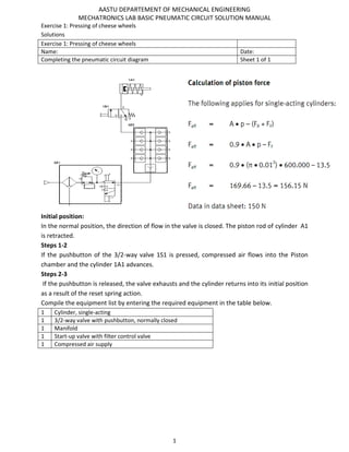
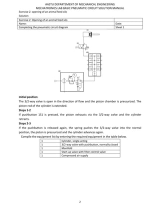
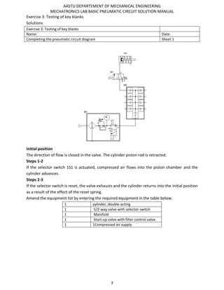
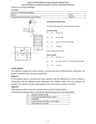
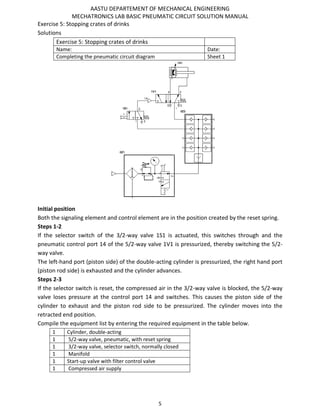
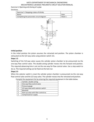
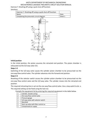
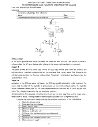
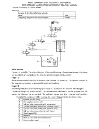
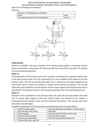
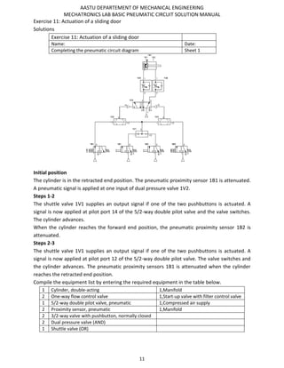
SlideShare a Scribd company logo
1 of 24
Download to read offline
AASTU DEPARTEMENT OF MECHANICAL ENGINEERING
MECHATRONICS LAB BASIC PNEUMATIC CIRCUIT SOLUTION MANUAL
1
Exercise 1: Pressing of cheese wheels
Solutions
Exercise 1: Pressing of cheese wheels
Name: Date:
Completing the pneumatic circuit diagram Sheet 1 of 1
Initial position:
In the normal position, the direction of flow in the valve is closed. The piston rod of cylinder A1
is retracted.
Steps 1-2
If the pushbutton of the 3/2-way valve 1S1 is pressed, compressed air flows into the Piston
chamber and the cylinder 1A1 advances.
Steps 2-3
If the pushbutton is released, the valve exhausts and the cylinder returns into its initial position
as a result of the reset spring action.
Compile the equipment list by entering the required equipment in the table below.
1 Cylinder, single-acting
1 3/2-way valve with pushbutton, normally closed
1 Manifold
1 Start-up valve with filter control valve
1 Compressed air supply
AASTU DEPARTEMENT OF MECHANICAL ENGINEERING
MECHATRONICS LAB BASIC PNEUMATIC CIRCUIT SOLUTION MANUAL
2
Exercise 2: opening of an animal feed silo
Solution
Exercise 2: Opening of an animal feed silo
Name: Date:
Completing the pneumatic circuit diagram Sheet 1
Initial position
The 3/2-way valve is open in the direction of flow and the piston chamber is pressurized. The
piston rod of the cylinder is extended.
Steps 1-2
If pushbutton 1S1 is pressed, the piston exhausts via the 3/2-way valve and the cylinder
retracts.
Steps 2-3
If the pushbutton is released again, the spring pushes the 3/2-way valve into the normal
position, the piston is pressurized and the cylinder advances again.
Compile the equipment list by entering the required equipment in the table below.
1 Cylinder, single-acting
1 3/2-way valve with pushbutton, normally closed
1 Manifold
1 Start-up valve with filter control valve
1 Compressed air supply
AASTU DEPARTEMENT OF MECHANICAL ENGINEERING
MECHATRONICS LAB BASIC PNEUMATIC CIRCUIT SOLUTION MANUAL
3
Exercise 3: Testing of key blanks
Solutions
Exercise 3: Testing of key blanks
Name: Date:
Completing the pneumatic circuit diagram Sheet 1
Initial position
The direction of flow is closed in the valve. The cylinder piston rod is retracted.
Steps 1-2
If the selector switch 1S1 is actuated, compressed air flows into the piston chamber and the
cylinder advances.
Steps 2-3
If the selector switch is reset, the valve exhausts and the cylinder returns into the initial position
as a result of the effect of the reset spring.
Amend the equipment list by entering the required equipment in the table below.
1 yylinder, double-acting
1 5/2-way valve with selector switch
1 Manifold
1 Start-up valve with filter control valve
1 1Compressed air supply
AASTU DEPARTEMENT OF MECHANICAL ENGINEERING
MECHATRONICS LAB BASIC PNEUMATIC CIRCUIT SOLUTION MANUAL
4
Exercise 4: Sorting of packages
Solutions
Exercise 4: Sorting of packages
Name: Date:
Completing the pneumatic circuit diagram Sheet 1
Initial position
The righthand supply port of the cylinder is pressurised and the lefthand port exhausted. The
piston is retained in the retracted end position.
Steps 1-2
If the selector switch is actuated the valve switches and the lefthand port of the cylinder is
pressurised and the righthand port exhausted. The cylinder moves into the forward end
position. The cylinder remains in this position even if the selector switch is not held.
Steps 2-3
If the selector switch is reset the cylinder returns into the initial position.
Compile the equipment list by entering the required equipment in the table below.
1 yylinder, double-acting
1 5/2-way valve with selector switch
1 Manifold
1 Start-up valve with filter control valve
1 1Compressed air supply
AASTU DEPARTEMENT OF MECHANICAL ENGINEERING
MECHATRONICS LAB BASIC PNEUMATIC CIRCUIT SOLUTION MANUAL
5
Exercise 5: Stopping crates of drinks
Solutions
Exercise 5: Stopping crates of drinks
Name: Date:
Completing the pneumatic circuit diagram Sheet 1
Initial position
Both the signaling element and control element are in the position created by the reset spring.
Steps 1-2
If the selector switch of the 3/2-way valve 1S1 is actuated, this switches through and the
pneumatic control port 14 of the 5/2-way valve 1V1 is pressurized, thereby switching the 5/2-
way valve.
The left-hand port (piston side) of the double-acting cylinder is pressurized, the right hand port
(piston rod side) is exhausted and the cylinder advances.
Steps 2-3
If the selector switch is reset, the compressed air in the 3/2-way valve is blocked, the 5/2-way
valve loses pressure at the control port 14 and switches. This causes the piston side of the
cylinder to exhaust and the piston rod side to be pressurized. The cylinder moves into the
retracted end position.
Compile the equipment list by entering the required equipment in the table below.
1 Cylinder, double-acting
1 5/2-way valve, pneumatic, with reset spring
1 3/2-way valve, selector switch, normally closed
1 Manifold
1 Start-up valve with filter control valve
1 Compressed air supply
AASTU DEPARTEMENT OF MECHANICAL ENGINEERING
MECHATRONICS LAB BASIC PNEUMATIC CIRCUIT SOLUTION MANUAL
6
Exercise 6: Opening and closing of a pipe
Solutions
Exercise 5: Stopping crates of drinks
Name: Date:
Completing the pneumatic circuit diagram Sheet 1
Initial position
In the initial position the piston assumes the retracted end position. The piston chamber is
exhausted via the 5/2-way valve using selector switch 1S1.
Steps 1-2
Switching of the 5/2-way valve causes the cylinder piston chamber to be pressurized via the
one-way flow control valve. The double-acting cylinder moves into the forward end position.
The required advancing time is set via the one-way for flow control valve. Use a stop watch to
do so. The required setting can be fixed via the lock nut.
Steps 2-3
When the selector switch is reset the cylinder piston chamber is pressurized via the one-way
flow control valve and the 5/2-way valve. The cylinder moves into the retracted end position.
Compile the equipment list by entering the required equipment in the table below.
1 Cylinder, double-acting
2 One-way flow control valve
2 Pressure gauge
1 5/2-way valve with selector switch
1 Manifold
1 Start-up valve with filter control va
1 Compressed air supply
AASTU DEPARTEMENT OF MECHANICAL ENGINEERING
MECHATRONICS LAB BASIC PNEUMATIC CIRCUIT SOLUTION MANUAL
7
Exercise 7: Shutting off using a quick shut-off function
Solutions
Exercise 7: Shutting off using a quick shut-off function
Name: Date:
Completing the pneumatic circuit diagram Sheet 1
Initial position
In the initial position, the piston assumes the retracted end position. The piston chamber is
exhausted via the 5/2-way valve 1S1.
Steps 1-2
Switching of the 5/2-way valve causes the cylinder piston chamber to be pressurized via the
one-way flow control valve. The cylinder advances into the forward end position.
Steps 2-3
Resetting of the selector switch causes the cylinder piston chamber to be pressurized via the
one-way flow control valve and the 5/2-way valve. The cylinder moves into the retracted end
position.
The required retracting time is set via the one-way flow control valve. Use a stop watch to do o.
The required setting can be fixed using the lock nut.
Compile the equipment list by entering the required equipment in the table below.
1 Cylinder, double-acting
2 One-way flow control valve
2 Pressure gauge
1 5/2-way valve with selector switch
1 Manifold
1 Start-up valve with filter control va
1 Compressed air supply
AASTU DEPARTEMENT OF MECHANICAL ENGINEERING
MECHATRONICS LAB BASIC PNEUMATIC CIRCUIT SOLUTION MANUAL
8
Exercise 8: Actuating a shut-off device
Solutions
Exercise 8: Actuating a shut-off device
Name: Date:
Completing the pneumatic circuit diagram Sheet 1
Initial position
In the initial position the piston assumes the retracted end position. The piston chamber is
exhausted via the 5/2-way double-pilot valve and the piston rod chamber is pressurized.
Steps 1-2
Actuation of the 3/2-way valve 1S1 causes the 5/2-way double pilot valve to reverse, the
cylinder piston chamber is pressurized via the one-way flow control valve. The double-acting
cylinder advances into the forward end position. The piston rod chamber is exhausted via the
quick exhaust valve.
Steps 2-3
Actuation of the 3/2-way valve 1S2 causes the 5/2-way double pilot valve to be reversed. The
piston rod chamber of the cylinder is pressurized via the quick exhaust valve. The cylinder
piston chamber is exhausted via the one-way flow control valve and the 5/2-way double pilot
valve. The cylinder moves into the retracted end position.
Retracting time .The required retracting time is set via the one-way flow control valve. Use a
stop watch to do so. The required flow control setting can be fixed using the lock nut.
Compile the equipment list by entering the required equipment in the table below.
1 Cylinder, double-acting
1 One-way flow control valve
1 Quick exhaust valve
1 Pressure gauge
1 5/2-way double pilot valve
2 3/2-way valve with pushbutton, normally closed
1 Manifold
1 Start-up valve with filter control valve
1 Compressed air supply
AASTU DEPARTEMENT OF MECHANICAL ENGINEERING
MECHATRONICS LAB BASIC PNEUMATIC CIRCUIT SOLUTION MANUAL
9
Exercise 9: Brushing of cheese wheels
Solutions
Exercise 9: Brushing of cheese wheels
Name: Date:
Completing the pneumatic circuit diagram Sheet 1
Initial position
Pressure is available. The piston chamber of the double-acting cylinder is exhausted, the piston
rod chamber is pressurized and the cylinder is in the retracted end position.
Steps 1-2
If the pushbutton of valve 1S1 is actuated, the cylinder 1A1 advances. The cylinder remains in
the forward end position as a result of the self-latching loop.
Steps 2-3
Once the pushbutton of the normally open valve 1S2 is actuated the cylinder retracts again.
The self-latching loop is switched off. The 5/2-way valve switches to normal position and the
piston rod chamber is pressurized. The cylinder moves into the retracted end position.
Compile the equipment list by entering the required equipment in the table below.
1 Cylinder, double-acting
2 One-way flow control valve
1 5/2-way valve, pneumatic, with spring return
1 3/2-way valve with pushbutton, normally closed
1 3/2-way valve with pushbutton, normally open
1 3/2-way valve, pneumatic, normally closed
1 Shuttle valve (OR)
1 Manifold
1 Start-up valve with filter control valve
1 Compessed air supply
AASTU DEPARTEMENT OF MECHANICAL ENGINEERING
MECHATRONICS LAB BASIC PNEUMATIC CIRCUIT SOLUTION MANUAL
10
Exercise 10: Clamping of a workpiece
Solutions
Exercise 10: Clamping of a workpiece
Name: Date:
Completing the pneumatic circuit diagram Sheet 1
Initial position
Pressure is available. The piston chamber of the double-acting cylinder is exhausted and the
piston rod chamber is pressurized. The 3/2-way roller lever valve 1B1 is actuated. The cylinder
is in the retracted end position.
Steps 1-2
If the pushbutton of the 3/2-way valve 1S1 is actuated, compressed air is applied at both inputs
of the dual pressure valve 1V1 and compressed air is now available at the output of the dual
pressure valve. The 5/2-way double pilot valve 1V2 is reversed via the signal applied at the
control port 14.This causes the cylinder to reverse and the piston to advance. The 3/2-way
roller lever valve switches to normal position and the output signal at the dual pressure valve is
switched off. The cylinder remains in the forward end position due to the self-latching circuit.
Steps 2-3
Actuation of the pushbutton on the 3/2-way valve 1S2 causes the 5/2-way double pilot valve
1V2 to reverse again (signal at pilot port 12).The piston rod chamber of the cylinder is
pressurized and the cylinder moves into the retracted end position. The 3/2-way roller lever
valve 1B1 is actuated again.
Compile the equipment list by entering the required equipment in the table below.
1 Cylinder, double-acting 1,3/2-way valve with pushbutton, normally closed
2 One-way flow control valve 1,Manifold
2 Pressure gauge 1,Start-up valve with filter control valve
1 5/2-way valve, pneumatic 1,Compressed air supply
1 Dual pressure valve (AND) 2,3/2-way valve with pushbutton, NC
1 3/2-way roller lever valve, NC
AASTU DEPARTEMENT OF MECHANICAL ENGINEERING
MECHATRONICS LAB BASIC PNEUMATIC CIRCUIT SOLUTION MANUAL
11
Exercise 11: Actuation of a sliding door
Solutions
Exercise 11: Actuation of a sliding door
Name: Date:
Completing the pneumatic circuit diagram Sheet 1
Initial position
The cylinder is in the retracted end position. The pneumatic proximity sensor 1B1 is attenuated.
A pneumatic signal is applied at one input of dual pressure valve 1V2.
Steps 1-2
The shuttle valve 1V1 supplies an output signal if one of the two pushbuttons is actuated. A
signal is now applied at pilot port 14 of the 5/2-way double pilot valve and the valve switches.
The cylinder advances.
When the cylinder reaches the forward end position, the pneumatic proximity sensor 1B2 is
attenuated.
Steps 2-3
The shuttle valve 1V1 supplies an output signal if one of the two pushbuttons is actuated. A
signal is now applied at pilot port 12 of the 5/2-way double pilot valve. The valve switches and
the cylinder advances. The pneumatic proximity sensors 1B1 is attenuated when the cylinder
reaches the retracted end position.
Compile the equipment list by entering the required equipment in the table below.
1 Cylinder, double-acting 1,Manifold
2 One-way flow control valve 1,Start-up valve with filter control valve
1 5/2-way double pilot valve, pneumatic 1,Compressed air supply
2 Proximity sensor, pneumatic 1,Manifold
2 3/2-way valve with pushbutton, normally closed
2 Dual pressure valve (AND)
1 Shuttle valve (OR)
AASTU DEPARTEMENT OF MECHANICAL ENGINEERING
MECHATRONICS LAB BASIC PNEUMATIC CIRCUIT SOLUTION MANUAL
12
Exercise 12: Feeding of workpieces
Solutions
Exercise 12: Feeding of workpieces
Name: Date:
Completing the pneumatic circuit diagram Sheet 1
Initial position
Compressed air is available. The cylinder is in the retracted end position. The pneumatic
proximity sensor 1B1 is attenuated and switched in free-flow direction. The piston rod chamber
is pressurized.
Steps 1-2
The 3/2-way valve 1S2 is not actuated unless the withdrawal area is free. The dual pressure
valve 1V1 does not supply an output signal, the 5/2-way double pilot valve cannot be reversed.
The 3/2-way valve 1S2 is actuated if the withdrawal area is free. The dual pressure valve 1V1
supplies an output signal. If the pushbutton of the 3/2-way valve 1S1 is actuated, the dual
pressure valve 1V2 supplies an output signal and a signal is applied at pilot port 14 of the 5/2-
way double pilot valve. The 5/2-way double pilot valve reverses and the cylinder advances.
Steps 2-3
The pneumatic proximity sensor 1B2 is attenuated and switches in the free-flow direction. A
signal is applied at pilot port 12 of the 5/2-way double pilot valve. The 5/2-way double pilot
valve 1V3 reverses and the cylinder moves into the retracted end position. The pneumatic limit
switch 1B1 is attenuated and switches in the free- flow direction.
Steps 3-1 Same as step 1
AASTU DEPARTEMENT OF MECHANICAL ENGINEERING
MECHATRONICS LAB BASIC PNEUMATIC CIRCUIT SOLUTION MANUAL
13
Exercise 12: Feeding of workpieces
Solutions
Exercise 12: Feeding of workpieces
Name: Date:
Completing the pneumatic circuit diagram Sheet 2
Compile the equipment list by entering the required equipment in the table below.
1 Cylinder, double-acting
2 One-way flow control valve
1 5/2-way double pilot valve, pneumatic
2 Proximity sensor, pneumatic
2 3/2-way valve with pushbutton, normally closed
2 Dual pressure valve (AND)
1 Shuttle valve (OR)
1 Manifold
1 Start-up valve with filter control valve
1 Compressed air supply
AASTU DEPARTEMENT OF MECHANICAL ENGINEERING
MECHATRONICS LAB BASIC PNEUMATIC CIRCUIT SOLUTION MANUAL
14
Exercise 13: Crushing of drinks cans
Exercise 13: Crushing of drinks cans Solutions
Name: Date:
Completing the pneumatic circuit diagram Sheet 1
Initial position
The double-acting cylinder is in the retracted end position. The pneumatic proximity sensor 1B1
is actuated and switched to free-flow direction. Compressed air is available. The required
pressure is preset at the pressure regulating valve of the service unit. The required pressure is
set at the pressure sequence valve.
Steps 1-2 :The pushbutton of valve 1S1 is actuated whereby the condition at the dual pressur
valve (AND) 1V3 becomes true. The 5/2-way double pilot valve 1V5 is switched in the operating
position and the double-acting cylinder advances.
Steps 2-3 : The pneumatic proximity sensor 1B2 is actuated and switches into the operating
position. The 5/2-way double pilot valve 1V5 is reversed via the shuttle valve (OR) 1V4.
Alternatively, this process can be initiated via the pushbutton of valve 1S2. The 5/ way double
pilot valve is reversed via the shuttle valve (OR) 1V4. The double-acting cylinder moves into the
initial position and the process is completed when the pneumatic proximity sensor 1B1 is
actuated.
Compile the equipment list by entering the required equipment in the table below.
1 Cylinder, double-acting 1 Compressed air supply
2 One-way flow control valve
1 5/2-way double pilot valve, pneumatic
2 Proximity sensor, pneumatic
2 3/2-way valve with pushbutton, normally closed
1 Dual pressure valve (AND)
1 Shuttle valve (OR)and (1)Manifold
1 Pressure sequence valve
1 Pressure regulating valve
1 Start-up valve with filter control valve
AASTU DEPARTEMENT OF MECHANICAL ENGINEERING
MECHATRONICS LAB BASIC PNEUMATIC CIRCUIT SOLUTION MANUAL
15
Exercise 14: Packaging of brochures
Solutions
Exercise 14: Packaging of brochures
Name: Date:
Completing the pneumatic circuit diagram Sheet 1
Initial position
The double-acting cylinder is in the retracted end position. The pneumatic limit switch
1B1 is attenuated and switched in free-flow direction. Compressed air is available. The
desired pressure is preset at the pressure regulating valve of the service unit, the
pressure sequence valve and at the pressure regulating valve in the cylinder supply air.
Steps 1-2
Pushbutton valve 1S1 is actuated and switches in the free-flow direction. The pneumatic
proximity sensor 1B1 is switched to operating position and consequently the condition at
the dual pressure valve (AND) 1V3 becomes true and the 5/2-way double pilot valve 1V4
is switched to operating position. The double-acting cylinder advances pressure
regulated.
Steps 2-3
Pushbutton 1S2 is actuated and switches in free-flow direction. This causes the 5/2-way
double pilot valve to reverse. The double-acting cylinder returns to the initial position.
The process is completed if the pneumatic proximity sensor 1B1 is attenuated.
Compile the equipment list by entering the required equipment in the table below.
AASTU DEPARTEMENT OF MECHANICAL ENGINEERING
MECHATRONICS LAB BASIC PNEUMATIC CIRCUIT SOLUTION MANUAL
16
Exercise 14: Packaging of brochures
Solutions
Exercise 14: Packaging of brochures
Name: Date:
Completing the pneumatic circuit diagram Sheet 2
1 Cylinder, double-acting
2 One-way flow control valve
1 5/2-way double-pilot valve, pneumatic
1 Proximity sensor, pneumatic
2 3/2-way valve with pushbutton, normally closed
1 Dual pressure valve (AND)
1 Pressure sequence valve
1 Pressure regulating valve
1 Manifold
1 Start-up valve with filter control valve
1 Compressed air supply
AASTU DEPARTEMENT OF MECHANICAL ENGINEERING
MECHATRONICS LAB BASIC PNEUMATIC CIRCUIT SOLUTION MANUAL
17
Exercise 15: Fitting of locking clips
Solutions
Exercise 15: Fitting of locking clips
Name: Date:
Completing the pneumatic circuit diagram Sheet 1
Initial position
The double-acting cylinder is in the retracted end position. The pneumatic proximity sensor
1B1 is attenuated. Compressed air is available. The required pressure is set at the pressure
regulating valve and pressure sequence valve.
Steps 1-2
Pushbutton 1S1 is actuated and the pneumatic proximity sensor 1B1 is attenuated,
consequently the condition at the first dual pressure valve (AND) 1V3 becomes true. When the
pressure sequence valve has switched with sufficient pressure, the 3/2-way valve is switched
into the operating position. The condition at the second two-way valve (AND) 1V5
consequently becomes true and the 5/2-way double pilot valve switches reverses into the
operating position. The double-acting cylinder advances.
Steps 2-3
The pneumatic proximity sensor 1B2 is attenuated and switches into the operating position.
The 5/2-way double pilot valve is reversed. The double-acting cylinder returns into the initial
position. The process is completed if the pneumatic proximity sensor 1B1 is attenuated.
AASTU DEPARTEMENT OF MECHANICAL ENGINEERING
MECHATRONICS LAB BASIC PNEUMATIC CIRCUIT SOLUTION MANUAL
18
Exercise 15: Fitting of locking clips
Solutions
Exercise 15: Fitting of locking clips
Name: Date:
Completing the pneumatic circuit diagram Sheet 2
Compile the equipment list by entering the required equipment in the table below.
1 Cylinder, double-acting
2 One-way flow control valve
1 5/2-way double pilot valve, pneumatic
2 Proximity sensor, pneumatic
1 3/2-way valve, pneumatic, normally open
1 3/2-way valve with pushbutton, normally closed
2 Dual pressure valve (AND)
1 Pressure sequence valve
1 Pressure regulating valve
1 Manifold
1 Start-up valve with filter control valve
1 Compressed air supply
AASTU DEPARTEMENT OF MECHANICAL ENGINEERING
MECHATRONICS LAB BASIC PNEUMATIC CIRCUIT SOLUTION MANUAL
19
Exercise 16: Labelling of paint pots
Solutions
Exercise 16: Labelling of paint pots
Name: Date:
Completing the pneumatic circuit diagram Sheet 1
Initial position
The double-acting cylinder is in the retracted end position. The pneumatic proximity sensor 1B1
is attenuated. Compressed air is available. The desired pressure is set at the pressure regulating
valve.
Steps 1-2
Pushbutton 1S1 is actuated and the pneumatic proximity sensor 1B1 is attenuated;
consequently the condition at the first dual pressure valve (AND) 1V2 becomes true and the
5/2-way double pilot valve 1V4 switches into the operating position. The double-acting cylinder
advances using minimal pressure.
Steps 2-3
The pneumatic proximity sensor 1B2 is attenuated and switches into the operating position.
This causes compressed air to be supplied to the time delay valve 1V3 and to switch after a
preset time interval. The 5/2-way pilot valve is switched back and the double-acting cylinder
returns to the initial position using minimal pressure. The piston chamber is exhausted via the
quick exhaust valve. The process is completed if the pneumatic proximity sensor 1B1 is
attenuated.
AASTU DEPARTEMENT OF MECHANICAL ENGINEERING
MECHATRONICS LAB BASIC PNEUMATIC CIRCUIT SOLUTION MANUAL
20
Exercise 16: Labelling of paint pots
Solutions
Exercise 16: Labelling of paint pots
Name: Date:
Completing the pneumatic circuit diagram Sheet 2
Compile the equipment list by entering the required equipment in the table below.
1 Cylinder, double-acting
1 One-way flow control valve
1 Quick exhaust valve
1 5/2-way double pilot valve, pneumatic
2 Proximity sensor, pneumatic
1 3/2-way valve with pushbutton, normally closed
1 Time delay valve
1 Dual pressure valve (AND)
1 Pressure regulating valve with pressure gauge
1 Pressure gauge
1 Manifold
1 Start-up valve with filter control valve
1 Compressed air supply
AASTU DEPARTEMENT OF MECHANICAL ENGINEERING
MECHATRONICS LAB BASIC PNEUMATIC CIRCUIT SOLUTION MANUAL
21
Exercise 17: Cleaning of workpieces
Solutions
Exercise 17: Cleaning of workpieces
Name: Date:
Completing the pneumatic circuit diagram Sheet 1
Initial position
The cylinder assumes the retracted end position in the initial position and actuates the 3/2-way
roller lever valve 1B1. The control element 1V4 (5/2-way double pilot valve) assumes the
righthand switching position. The signal latch 1V2 (3/2-way double pilot valve) is also in the
righthand switching position. The desired pressure is set at the pressure regulating valve.
Steps 1-2
Actuation of START button 1S1 causes the signal latch 1V2 to switch. Compressed air is applied
at the input of the time delay valve 1V1. The 5/2-way double pilot valve 1V4 is reversed via the
actuated 3/2-way roller lever valve 1B1 and the shuttle valve (OR) 1V3; the cylinder advances.
Overtravelling of the middle pneumatic proximity sensor 1B3 has no effect since the same pilot
input of the control element is actuated.
Steps 2-3
The pneumatic proximity sensor 1B2 is actuated in the forward end position. The control
element (5/2-way double solenoid valve) reverses. The cylinder partially retracts and actuates
the middle pneumatic proximity sensor 1B3.
AASTU DEPARTEMENT OF MECHANICAL ENGINEERING
MECHATRONICS LAB BASIC PNEUMATIC CIRCUIT SOLUTION MANUAL
22
Exercise 17: Cleaning of workpieces
Solutions
Exercise 17: Cleaning of workpieces
Name: Date:
Completing the pneumatic circuit diagram Sheet 2
Steps 3-4
Actuation of the middle pneumatic proximity sensor causes the cylinder to reverse again. The
switching function takes only a few milliseconds so that the switching
cam does not over travel the pneumatic proximity sensor 1B3.
Steps 4-5
See steps 2-3.
Compile the equipment list by entering the required equipment in the table below.
1 Cylinder, double-acting
2 One-way flow control valve
1 5/2-way double pilot valve, pneumatic
1 3/2-way double pilot valve, pneumatic
2 Proximity sensor, pneumatic
1 3/2-way roller lever valve, normally closed
1 3/2-way valve with pushbutton, normally close
1 Time delay valve
1 Shuttle valve (OR)
1 Manifold
1 Start-up valve with filter control valve
1 Compressed air supply
AASTU DEPARTEMENT OF MECHANICAL ENGINEERING
MECHATRONICS LAB BASIC PNEUMATIC CIRCUIT SOLUTION MANUAL
23
Exercise 18: Pressing in of lids
Solutions
Exercise 18: Pressing in of lids
Name: Date:
Completing the pneumatic circuit diagram Sheet 1
Initial position
Pressure is available. Both cylinders assume the retracted end position in the initial position.
The piston of the double-acting cylinder attenuates the pneumatic proximity sensor (2B1); this
switches in free-flow direction. The control elements 1V2 and 2V1 (5/2-way double pilot valve
and 3/2-way double pilot valve) assume the right-hand switching position.
Steps 1-2
Actuation of pushbutton 1S1 causes the condition at the dual pressure valve (AND) 1V1 to
become true. The 3/2-way double pilot valve 1V2 reverses. The single-acting cylinder advances
with supply air restricted.
Steps 2-3
Roller lever valve 1B2 is actuated when the single-acting cylinder reaches is forward end
position and switches the 5/2-way double pilot valve 2V1. The double-acting cylinder advances
into the forward end position, where it attenuates the pneumatic proximity sensor 2B2. This
switches to free-flow direction.
Steps 3-4
The 5/2-way double pilot valve 2V1 and 3/2-way double pilot valve 1V2 reverse. Both cylinders
retract. The process is completed when the piston of the double- acting cylinder attenuates the
pneumatic proximity sensor (2B1) and this switches in free-flow direction.
.
AASTU DEPARTEMENT OF MECHANICAL ENGINEERING
MECHATRONICS LAB BASIC PNEUMATIC CIRCUIT SOLUTION MANUAL
24
Exercise 18: Pressing in of lids
Solutions
Exercise 18: Pressing in of lids
Name: Date:
Completing the pneumatic circuit diagram Sheet 2
Compile the equipment list by entering the required equipment in the table below
1 Cylinder, double-acting
1 Cylinder, single-acting
2 One-way flow control valve
1 5/2-way double pilot valve, pneumatic
1 3/2-way double pilot valve, pneumatic
2 Proximity sensor, pneumatic
1 3/2-way roller lever valve, normally closed
1 3/2-way valve with pushbutton, normally closed
1 Dual pressure valve (AND)
1 Manifold
1 Start-up valve with filter control valve
1 Compressed air supply

More Related Content

What's hot

Simbol hidraulik
Simbol hidraulikSimbol hidraulik
Simbol hidrauliknorbahiah
 
J4012 pneumatik dan hidraulik unit10
J4012 pneumatik dan hidraulik unit10J4012 pneumatik dan hidraulik unit10
J4012 pneumatik dan hidraulik unit10Asraf Malik
 
Asas Sistem pneumatik -123
Asas Sistem pneumatik -123Asas Sistem pneumatik -123
Asas Sistem pneumatik -123KEN KEN
 
Chapter 3 electro pneumatic.updated
Chapter 3 electro pneumatic.updatedChapter 3 electro pneumatic.updated
Chapter 3 electro pneumatic.updatedHattori Sidek
 
Litar pneumatik
Litar pneumatikLitar pneumatik
Litar pneumatikMdElias19
 
Kertas penerangan k1
Kertas penerangan k1Kertas penerangan k1
Kertas penerangan k1lyana mohamad
 
J4012 pneumatik dan hidraulik unit3
J4012 pneumatik dan hidraulik unit3J4012 pneumatik dan hidraulik unit3
J4012 pneumatik dan hidraulik unit3Asraf Malik
 
Instalación compresores wabco
Instalación compresores wabcoInstalación compresores wabco
Instalación compresores wabcoJonathan Ortiz
 
SISTEM KLAC-TOPIK 3: MENSERVIS PAM KLAC HIDRAULIK
SISTEM KLAC-TOPIK 3: MENSERVIS PAM KLAC HIDRAULIKSISTEM KLAC-TOPIK 3: MENSERVIS PAM KLAC HIDRAULIK
SISTEM KLAC-TOPIK 3: MENSERVIS PAM KLAC HIDRAULIKMuhammad Amirul
 
J4012 pneumatik dan hidraulik unit5
J4012 pneumatik dan hidraulik unit5J4012 pneumatik dan hidraulik unit5
J4012 pneumatik dan hidraulik unit5Asraf Malik
 
J4012 pneumatik dan hidraulik unit7
J4012 pneumatik dan hidraulik unit7J4012 pneumatik dan hidraulik unit7
J4012 pneumatik dan hidraulik unit7Asraf Malik
 
3 electro hydraulic, component, circuits
3 electro hydraulic, component, circuits3 electro hydraulic, component, circuits
3 electro hydraulic, component, circuitsDr.R. SELVAM
 
Hydraulic Circuit Design and Analysis , dr.samir elshamy
Hydraulic Circuit Design and Analysis , dr.samir elshamyHydraulic Circuit Design and Analysis , dr.samir elshamy
Hydraulic Circuit Design and Analysis , dr.samir elshamyDr.Samir el-shamy
 
Working elements of Pneumatic System with Circuits, Safety, Installation
Working elements of Pneumatic System with Circuits, Safety, InstallationWorking elements of Pneumatic System with Circuits, Safety, Installation
Working elements of Pneumatic System with Circuits, Safety, InstallationMohammad Azam Khan
 

What's hot (20)

Pneumatic Lab 3 JJ512
Pneumatic Lab 3 JJ512Pneumatic Lab 3 JJ512
Pneumatic Lab 3 JJ512
 
Simbol hidraulik
Simbol hidraulikSimbol hidraulik
Simbol hidraulik
 
Lab pneumatic 2
Lab pneumatic 2Lab pneumatic 2
Lab pneumatic 2
 
J4012 pneumatik dan hidraulik unit10
J4012 pneumatik dan hidraulik unit10J4012 pneumatik dan hidraulik unit10
J4012 pneumatik dan hidraulik unit10
 
Asas Sistem pneumatik -123
Asas Sistem pneumatik -123Asas Sistem pneumatik -123
Asas Sistem pneumatik -123
 
Chapter 3 electro pneumatic.updated
Chapter 3 electro pneumatic.updatedChapter 3 electro pneumatic.updated
Chapter 3 electro pneumatic.updated
 
Litar pneumatik
Litar pneumatikLitar pneumatik
Litar pneumatik
 
Pneumatic system
Pneumatic systemPneumatic system
Pneumatic system
 
PNEUMATIC
PNEUMATICPNEUMATIC
PNEUMATIC
 
Hydraulic valves
Hydraulic valvesHydraulic valves
Hydraulic valves
 
Kertas penerangan k1
Kertas penerangan k1Kertas penerangan k1
Kertas penerangan k1
 
J4012 pneumatik dan hidraulik unit3
J4012 pneumatik dan hidraulik unit3J4012 pneumatik dan hidraulik unit3
J4012 pneumatik dan hidraulik unit3
 
Instalación compresores wabco
Instalación compresores wabcoInstalación compresores wabco
Instalación compresores wabco
 
SISTEM KLAC-TOPIK 3: MENSERVIS PAM KLAC HIDRAULIK
SISTEM KLAC-TOPIK 3: MENSERVIS PAM KLAC HIDRAULIKSISTEM KLAC-TOPIK 3: MENSERVIS PAM KLAC HIDRAULIK
SISTEM KLAC-TOPIK 3: MENSERVIS PAM KLAC HIDRAULIK
 
J4012 pneumatik dan hidraulik unit5
J4012 pneumatik dan hidraulik unit5J4012 pneumatik dan hidraulik unit5
J4012 pneumatik dan hidraulik unit5
 
J4012 pneumatik dan hidraulik unit7
J4012 pneumatik dan hidraulik unit7J4012 pneumatik dan hidraulik unit7
J4012 pneumatik dan hidraulik unit7
 
3 electro hydraulic, component, circuits
3 electro hydraulic, component, circuits3 electro hydraulic, component, circuits
3 electro hydraulic, component, circuits
 
Hydraulic Circuit Design and Analysis , dr.samir elshamy
Hydraulic Circuit Design and Analysis , dr.samir elshamyHydraulic Circuit Design and Analysis , dr.samir elshamy
Hydraulic Circuit Design and Analysis , dr.samir elshamy
 
Unit1
Unit1Unit1
Unit1
 
Working elements of Pneumatic System with Circuits, Safety, Installation
Working elements of Pneumatic System with Circuits, Safety, InstallationWorking elements of Pneumatic System with Circuits, Safety, Installation
Working elements of Pneumatic System with Circuits, Safety, Installation
 

Similar to basic pneumatics.pdf

Experiment No 2.control.pdf
Experiment No 2.control.pdfExperiment No 2.control.pdf
Experiment No 2.control.pdfMahamad Jawhar
 
Ii air control valves
Ii air control valvesIi air control valves
Ii air control valvesmoroyusef
 
Lab pactice on pneumatic control systems
Lab pactice on pneumatic control systemsLab pactice on pneumatic control systems
Lab pactice on pneumatic control systemsEphremZemedkun
 
PNEUMATIC tools Industrial Training PPT P
PNEUMATIC tools Industrial Training PPT PPNEUMATIC tools Industrial Training PPT P
PNEUMATIC tools Industrial Training PPT PHumanCapitalServices
 
IL 0 Group II Group I Select GP I Select GP II Solution Basic P.pdf
IL 0 Group II Group I Select GP I Select GP II Solution  Basic P.pdfIL 0 Group II Group I Select GP I Select GP II Solution  Basic P.pdf
IL 0 Group II Group I Select GP I Select GP II Solution Basic P.pdferremmfab
 
pneumaticcircuits-140111054249-phpapp01 (2).pdf
pneumaticcircuits-140111054249-phpapp01 (2).pdfpneumaticcircuits-140111054249-phpapp01 (2).pdf
pneumaticcircuits-140111054249-phpapp01 (2).pdfJanreyTonga1
 
Pneumatic circuits.pptx
Pneumatic circuits.pptxPneumatic circuits.pptx
Pneumatic circuits.pptxssuser76b8fc1
 
3 a. industrial pneumatic circuit basic
3 a. industrial pneumatic circuit   basic3 a. industrial pneumatic circuit   basic
3 a. industrial pneumatic circuit basicDr.R. SELVAM
 
Classification of Pneumatic Elements Included Valves, Compressor
Classification of Pneumatic Elements Included Valves, CompressorClassification of Pneumatic Elements Included Valves, Compressor
Classification of Pneumatic Elements Included Valves, CompressorMohammad Azam Khan
 
Practical task 1 pneumatik june 2018
Practical task 1 pneumatik june 2018Practical task 1 pneumatik june 2018
Practical task 1 pneumatik june 2018zuhaila79
 
Single action cylinder
Single action cylinderSingle action cylinder
Single action cylinderrawaabdullah
 
B737 NG Air Systems
B737 NG Air SystemsB737 NG Air Systems
B737 NG Air Systemstheoryce
 
Pneumatics: Shuttle, Twin pressure, Quick Exhaust, Time Delay, FRL
Pneumatics: Shuttle, Twin pressure, Quick Exhaust, Time Delay, FRLPneumatics: Shuttle, Twin pressure, Quick Exhaust, Time Delay, FRL
Pneumatics: Shuttle, Twin pressure, Quick Exhaust, Time Delay, FRLAbhishek Patange
 
Control Valves .pdf
Control Valves .pdfControl Valves .pdf
Control Valves .pdfmarcos849547
 
Hydraulic and pneumatic control elements
Hydraulic and pneumatic control elementsHydraulic and pneumatic control elements
Hydraulic and pneumatic control elementsumesh chikhale
 
Pneumatics
PneumaticsPneumatics
Pneumaticsleotvrde
 

Similar to basic pneumatics.pdf (20)

Experiment No 2.control.pdf
Experiment No 2.control.pdfExperiment No 2.control.pdf
Experiment No 2.control.pdf
 
exp1 control lab.pdf
exp1 control lab.pdfexp1 control lab.pdf
exp1 control lab.pdf
 
Ii air control valves
Ii air control valvesIi air control valves
Ii air control valves
 
Lab pactice on pneumatic control systems
Lab pactice on pneumatic control systemsLab pactice on pneumatic control systems
Lab pactice on pneumatic control systems
 
PNEUMATIC tools Industrial Training PPT P
PNEUMATIC tools Industrial Training PPT PPNEUMATIC tools Industrial Training PPT P
PNEUMATIC tools Industrial Training PPT P
 
IL 0 Group II Group I Select GP I Select GP II Solution Basic P.pdf
IL 0 Group II Group I Select GP I Select GP II Solution  Basic P.pdfIL 0 Group II Group I Select GP I Select GP II Solution  Basic P.pdf
IL 0 Group II Group I Select GP I Select GP II Solution Basic P.pdf
 
Pneumatic circuits
Pneumatic circuitsPneumatic circuits
Pneumatic circuits
 
pneumaticcircuits-140111054249-phpapp01 (2).pdf
pneumaticcircuits-140111054249-phpapp01 (2).pdfpneumaticcircuits-140111054249-phpapp01 (2).pdf
pneumaticcircuits-140111054249-phpapp01 (2).pdf
 
Pneumatic circuits.pptx
Pneumatic circuits.pptxPneumatic circuits.pptx
Pneumatic circuits.pptx
 
3 a. industrial pneumatic circuit basic
3 a. industrial pneumatic circuit   basic3 a. industrial pneumatic circuit   basic
3 a. industrial pneumatic circuit basic
 
Classification of Pneumatic Elements Included Valves, Compressor
Classification of Pneumatic Elements Included Valves, CompressorClassification of Pneumatic Elements Included Valves, Compressor
Classification of Pneumatic Elements Included Valves, Compressor
 
Practical task 1 pneumatik june 2018
Practical task 1 pneumatik june 2018Practical task 1 pneumatik june 2018
Practical task 1 pneumatik june 2018
 
Single action cylinder
Single action cylinderSingle action cylinder
Single action cylinder
 
B737 NG Air Systems
B737 NG Air SystemsB737 NG Air Systems
B737 NG Air Systems
 
Pneumatics: Shuttle, Twin pressure, Quick Exhaust, Time Delay, FRL
Pneumatics: Shuttle, Twin pressure, Quick Exhaust, Time Delay, FRLPneumatics: Shuttle, Twin pressure, Quick Exhaust, Time Delay, FRL
Pneumatics: Shuttle, Twin pressure, Quick Exhaust, Time Delay, FRL
 
Control Valve.pdf
Control Valve.pdfControl Valve.pdf
Control Valve.pdf
 
Control Valves .pdf
Control Valves .pdfControl Valves .pdf
Control Valves .pdf
 
Hydraulic and pneumatic control elements
Hydraulic and pneumatic control elementsHydraulic and pneumatic control elements
Hydraulic and pneumatic control elements
 
Pneumatics
PneumaticsPneumatics
Pneumatics
 
Turning Table.pptx
Turning Table.pptxTurning Table.pptx
Turning Table.pptx
 

More from tilahunyeshiye (18)

5.3 Gear.pptx
5.3 Gear.pptx5.3 Gear.pptx
5.3 Gear.pptx
 
5.1 Screwed Fasteners.pptx
5.1 Screwed Fasteners.pptx5.1 Screwed Fasteners.pptx
5.1 Screwed Fasteners.pptx
 
4. Limits ,Tolerance and Fits.pptx
4. Limits ,Tolerance and Fits.pptx4. Limits ,Tolerance and Fits.pptx
4. Limits ,Tolerance and Fits.pptx
 
5.2 Bearings and Seals.pptx
5.2 Bearings and Seals.pptx5.2 Bearings and Seals.pptx
5.2 Bearings and Seals.pptx
 
composite final.pdf
composite final.pdfcomposite final.pdf
composite final.pdf
 
alebel.pdf
alebel.pdfalebel.pdf
alebel.pdf
 
inv 3.pdf
inv 3.pdfinv 3.pdf
inv 3.pdf
 
Chapter1.pdf
Chapter1.pdfChapter1.pdf
Chapter1.pdf
 
invoice 2.pdf
invoice 2.pdfinvoice 2.pdf
invoice 2.pdf
 
ic present.pdf
ic present.pdfic present.pdf
ic present.pdf
 
elect.pdf
elect.pdfelect.pdf
elect.pdf
 
Full page photo.pdf
Full page photo.pdfFull page photo.pdf
Full page photo.pdf
 
Drawing1-Model.pdf
Drawing1-Model.pdfDrawing1-Model.pdf
Drawing1-Model.pdf
 
Course Viberatio.pdf
Course Viberatio.pdfCourse Viberatio.pdf
Course Viberatio.pdf
 
z.pdf
z.pdfz.pdf
z.pdf
 
v.oxps.pdf
v.oxps.pdfv.oxps.pdf
v.oxps.pdf
 
s.pdf
s.pdfs.pdf
s.pdf
 
Screenshot (1).pdf
Screenshot (1).pdfScreenshot (1).pdf
Screenshot (1).pdf
 

Recently uploaded

Housewife Call Girls Sonagachi - 8250192130 Booking and charges genuine rate ...
Housewife Call Girls Sonagachi - 8250192130 Booking and charges genuine rate ...Housewife Call Girls Sonagachi - 8250192130 Booking and charges genuine rate ...
Housewife Call Girls Sonagachi - 8250192130 Booking and charges genuine rate ...Riya Pathan
 
Air-Hostess Call Girls Shobhabazar | 8250192130 At Low Cost Cash Payment Booking
Air-Hostess Call Girls Shobhabazar | 8250192130 At Low Cost Cash Payment BookingAir-Hostess Call Girls Shobhabazar | 8250192130 At Low Cost Cash Payment Booking
Air-Hostess Call Girls Shobhabazar | 8250192130 At Low Cost Cash Payment BookingRiya Pathan
 
fmovies-Movies hold a special place in the hearts
fmovies-Movies hold a special place in the heartsfmovies-Movies hold a special place in the hearts
fmovies-Movies hold a special place in the heartsa18205752
 
Call Girl Nagpur Roshni Call 7001035870 Meet With Nagpur Escorts
Call Girl Nagpur Roshni Call 7001035870 Meet With Nagpur EscortsCall Girl Nagpur Roshni Call 7001035870 Meet With Nagpur Escorts
Call Girl Nagpur Roshni Call 7001035870 Meet With Nagpur EscortsCall Girls in Nagpur High Profile
 
VIP Call Girls Service Banjara Hills Hyderabad Call +91-8250192130
VIP Call Girls Service Banjara Hills Hyderabad Call +91-8250192130VIP Call Girls Service Banjara Hills Hyderabad Call +91-8250192130
VIP Call Girls Service Banjara Hills Hyderabad Call +91-8250192130Suhani Kapoor
 
FULL ENJOY Call Girls In Mahipalpur Delhi Contact Us 8377087607
FULL ENJOY Call Girls In Mahipalpur Delhi Contact Us 8377087607FULL ENJOY Call Girls In Mahipalpur Delhi Contact Us 8377087607
FULL ENJOY Call Girls In Mahipalpur Delhi Contact Us 8377087607dollysharma2066
 
Call Girls Nikol 7397865700 Ridhima Hire Me Full Night
Call Girls Nikol 7397865700 Ridhima Hire Me Full NightCall Girls Nikol 7397865700 Ridhima Hire Me Full Night
Call Girls Nikol 7397865700 Ridhima Hire Me Full Nightssuser7cb4ff
 
Hot Call Girls In Goa 7028418221 Call Girls In Vagator Beach EsCoRtS
Hot Call Girls In Goa 7028418221 Call Girls In Vagator Beach EsCoRtSHot Call Girls In Goa 7028418221 Call Girls In Vagator Beach EsCoRtS
Hot Call Girls In Goa 7028418221 Call Girls In Vagator Beach EsCoRtSApsara Of India
 
Hifi Laxmi Nagar Call Girls Service WhatsApp -> 9999965857 Available 24x7 ^ D...
Hifi Laxmi Nagar Call Girls Service WhatsApp -> 9999965857 Available 24x7 ^ D...Hifi Laxmi Nagar Call Girls Service WhatsApp -> 9999965857 Available 24x7 ^ D...
Hifi Laxmi Nagar Call Girls Service WhatsApp -> 9999965857 Available 24x7 ^ D...srsj9000
 
1681275559_haunting-adeline and hunting.pdf
1681275559_haunting-adeline and hunting.pdf1681275559_haunting-adeline and hunting.pdf
1681275559_haunting-adeline and hunting.pdfTanjirokamado769606
 
Vip Udaipur Call Girls 9602870969 Dabok Airport Udaipur Escorts Service
Vip Udaipur Call Girls 9602870969 Dabok Airport Udaipur Escorts ServiceVip Udaipur Call Girls 9602870969 Dabok Airport Udaipur Escorts Service
Vip Udaipur Call Girls 9602870969 Dabok Airport Udaipur Escorts ServiceApsara Of India
 
Hi Class Call Girls In Goa 7028418221 Call Girls In Anjuna Beach Escort Services
Hi Class Call Girls In Goa 7028418221 Call Girls In Anjuna Beach Escort ServicesHi Class Call Girls In Goa 7028418221 Call Girls In Anjuna Beach Escort Services
Hi Class Call Girls In Goa 7028418221 Call Girls In Anjuna Beach Escort ServicesApsara Of India
 
Kolkata Call Girl Bara Bazar 👉 8250192130 ❣️💯 Available With Room 24×7
Kolkata Call Girl Bara Bazar 👉 8250192130 ❣️💯 Available With Room 24×7Kolkata Call Girl Bara Bazar 👉 8250192130 ❣️💯 Available With Room 24×7
Kolkata Call Girl Bara Bazar 👉 8250192130 ❣️💯 Available With Room 24×7Riya Pathan
 
Kolkata Call Girl Airport Kolkata 👉 8250192130 ❣️💯 Available With Room 24×7
Kolkata Call Girl Airport Kolkata 👉 8250192130 ❣️💯 Available With Room 24×7Kolkata Call Girl Airport Kolkata 👉 8250192130 ❣️💯 Available With Room 24×7
Kolkata Call Girl Airport Kolkata 👉 8250192130 ❣️💯 Available With Room 24×7Riya Pathan
 
Cash Payment Contact:- 7028418221 Goa Call Girls Service North Goa Escorts
Cash Payment Contact:- 7028418221 Goa Call Girls Service North Goa EscortsCash Payment Contact:- 7028418221 Goa Call Girls Service North Goa Escorts
Cash Payment Contact:- 7028418221 Goa Call Girls Service North Goa EscortsApsara Of India
 
Call Girl Nashik Saloni 7001305949 Independent Escort Service Nashik
Call Girl Nashik Saloni 7001305949 Independent Escort Service NashikCall Girl Nashik Saloni 7001305949 Independent Escort Service Nashik
Call Girl Nashik Saloni 7001305949 Independent Escort Service NashikCall Girls in Nagpur High Profile
 
VIP Call Girls Nagpur Megha Call 7001035870 Meet With Nagpur Escorts
VIP Call Girls Nagpur Megha Call 7001035870 Meet With Nagpur EscortsVIP Call Girls Nagpur Megha Call 7001035870 Meet With Nagpur Escorts
VIP Call Girls Nagpur Megha Call 7001035870 Meet With Nagpur Escortsranjana rawat
 
VIP Call Girl Kolhapur Aashi 8250192130 Independent Escort Service Kolhapur
VIP Call Girl Kolhapur Aashi 8250192130 Independent Escort Service KolhapurVIP Call Girl Kolhapur Aashi 8250192130 Independent Escort Service Kolhapur
VIP Call Girl Kolhapur Aashi 8250192130 Independent Escort Service KolhapurRiya Pathan
 
(Dipika) Call Girls in Bangur ! 8250192130 ₹2999 Only and Free Hotel Delivery...
(Dipika) Call Girls in Bangur ! 8250192130 ₹2999 Only and Free Hotel Delivery...(Dipika) Call Girls in Bangur ! 8250192130 ₹2999 Only and Free Hotel Delivery...
(Dipika) Call Girls in Bangur ! 8250192130 ₹2999 Only and Free Hotel Delivery...Riya Pathan
 
LE IMPOSSIBRU QUIZ (Based on Splapp-me-do)
LE IMPOSSIBRU QUIZ (Based on Splapp-me-do)LE IMPOSSIBRU QUIZ (Based on Splapp-me-do)
LE IMPOSSIBRU QUIZ (Based on Splapp-me-do)bertfelixtorre
 

Recently uploaded (20)

Housewife Call Girls Sonagachi - 8250192130 Booking and charges genuine rate ...
Housewife Call Girls Sonagachi - 8250192130 Booking and charges genuine rate ...Housewife Call Girls Sonagachi - 8250192130 Booking and charges genuine rate ...
Housewife Call Girls Sonagachi - 8250192130 Booking and charges genuine rate ...
 
Air-Hostess Call Girls Shobhabazar | 8250192130 At Low Cost Cash Payment Booking
Air-Hostess Call Girls Shobhabazar | 8250192130 At Low Cost Cash Payment BookingAir-Hostess Call Girls Shobhabazar | 8250192130 At Low Cost Cash Payment Booking
Air-Hostess Call Girls Shobhabazar | 8250192130 At Low Cost Cash Payment Booking
 
fmovies-Movies hold a special place in the hearts
fmovies-Movies hold a special place in the heartsfmovies-Movies hold a special place in the hearts
fmovies-Movies hold a special place in the hearts
 
Call Girl Nagpur Roshni Call 7001035870 Meet With Nagpur Escorts
Call Girl Nagpur Roshni Call 7001035870 Meet With Nagpur EscortsCall Girl Nagpur Roshni Call 7001035870 Meet With Nagpur Escorts
Call Girl Nagpur Roshni Call 7001035870 Meet With Nagpur Escorts
 
VIP Call Girls Service Banjara Hills Hyderabad Call +91-8250192130
VIP Call Girls Service Banjara Hills Hyderabad Call +91-8250192130VIP Call Girls Service Banjara Hills Hyderabad Call +91-8250192130
VIP Call Girls Service Banjara Hills Hyderabad Call +91-8250192130
 
FULL ENJOY Call Girls In Mahipalpur Delhi Contact Us 8377087607
FULL ENJOY Call Girls In Mahipalpur Delhi Contact Us 8377087607FULL ENJOY Call Girls In Mahipalpur Delhi Contact Us 8377087607
FULL ENJOY Call Girls In Mahipalpur Delhi Contact Us 8377087607
 
Call Girls Nikol 7397865700 Ridhima Hire Me Full Night
Call Girls Nikol 7397865700 Ridhima Hire Me Full NightCall Girls Nikol 7397865700 Ridhima Hire Me Full Night
Call Girls Nikol 7397865700 Ridhima Hire Me Full Night
 
Hot Call Girls In Goa 7028418221 Call Girls In Vagator Beach EsCoRtS
Hot Call Girls In Goa 7028418221 Call Girls In Vagator Beach EsCoRtSHot Call Girls In Goa 7028418221 Call Girls In Vagator Beach EsCoRtS
Hot Call Girls In Goa 7028418221 Call Girls In Vagator Beach EsCoRtS
 
Hifi Laxmi Nagar Call Girls Service WhatsApp -> 9999965857 Available 24x7 ^ D...
Hifi Laxmi Nagar Call Girls Service WhatsApp -> 9999965857 Available 24x7 ^ D...Hifi Laxmi Nagar Call Girls Service WhatsApp -> 9999965857 Available 24x7 ^ D...
Hifi Laxmi Nagar Call Girls Service WhatsApp -> 9999965857 Available 24x7 ^ D...
 
1681275559_haunting-adeline and hunting.pdf
1681275559_haunting-adeline and hunting.pdf1681275559_haunting-adeline and hunting.pdf
1681275559_haunting-adeline and hunting.pdf
 
Vip Udaipur Call Girls 9602870969 Dabok Airport Udaipur Escorts Service
Vip Udaipur Call Girls 9602870969 Dabok Airport Udaipur Escorts ServiceVip Udaipur Call Girls 9602870969 Dabok Airport Udaipur Escorts Service
Vip Udaipur Call Girls 9602870969 Dabok Airport Udaipur Escorts Service
 
Hi Class Call Girls In Goa 7028418221 Call Girls In Anjuna Beach Escort Services
Hi Class Call Girls In Goa 7028418221 Call Girls In Anjuna Beach Escort ServicesHi Class Call Girls In Goa 7028418221 Call Girls In Anjuna Beach Escort Services
Hi Class Call Girls In Goa 7028418221 Call Girls In Anjuna Beach Escort Services
 
Kolkata Call Girl Bara Bazar 👉 8250192130 ❣️💯 Available With Room 24×7
Kolkata Call Girl Bara Bazar 👉 8250192130 ❣️💯 Available With Room 24×7Kolkata Call Girl Bara Bazar 👉 8250192130 ❣️💯 Available With Room 24×7
Kolkata Call Girl Bara Bazar 👉 8250192130 ❣️💯 Available With Room 24×7
 
Kolkata Call Girl Airport Kolkata 👉 8250192130 ❣️💯 Available With Room 24×7
Kolkata Call Girl Airport Kolkata 👉 8250192130 ❣️💯 Available With Room 24×7Kolkata Call Girl Airport Kolkata 👉 8250192130 ❣️💯 Available With Room 24×7
Kolkata Call Girl Airport Kolkata 👉 8250192130 ❣️💯 Available With Room 24×7
 
Cash Payment Contact:- 7028418221 Goa Call Girls Service North Goa Escorts
Cash Payment Contact:- 7028418221 Goa Call Girls Service North Goa EscortsCash Payment Contact:- 7028418221 Goa Call Girls Service North Goa Escorts
Cash Payment Contact:- 7028418221 Goa Call Girls Service North Goa Escorts
 
Call Girl Nashik Saloni 7001305949 Independent Escort Service Nashik
Call Girl Nashik Saloni 7001305949 Independent Escort Service NashikCall Girl Nashik Saloni 7001305949 Independent Escort Service Nashik
Call Girl Nashik Saloni 7001305949 Independent Escort Service Nashik
 
VIP Call Girls Nagpur Megha Call 7001035870 Meet With Nagpur Escorts
VIP Call Girls Nagpur Megha Call 7001035870 Meet With Nagpur EscortsVIP Call Girls Nagpur Megha Call 7001035870 Meet With Nagpur Escorts
VIP Call Girls Nagpur Megha Call 7001035870 Meet With Nagpur Escorts
 
VIP Call Girl Kolhapur Aashi 8250192130 Independent Escort Service Kolhapur
VIP Call Girl Kolhapur Aashi 8250192130 Independent Escort Service KolhapurVIP Call Girl Kolhapur Aashi 8250192130 Independent Escort Service Kolhapur
VIP Call Girl Kolhapur Aashi 8250192130 Independent Escort Service Kolhapur
 
(Dipika) Call Girls in Bangur ! 8250192130 ₹2999 Only and Free Hotel Delivery...
(Dipika) Call Girls in Bangur ! 8250192130 ₹2999 Only and Free Hotel Delivery...(Dipika) Call Girls in Bangur ! 8250192130 ₹2999 Only and Free Hotel Delivery...
(Dipika) Call Girls in Bangur ! 8250192130 ₹2999 Only and Free Hotel Delivery...
 
LE IMPOSSIBRU QUIZ (Based on Splapp-me-do)
LE IMPOSSIBRU QUIZ (Based on Splapp-me-do)LE IMPOSSIBRU QUIZ (Based on Splapp-me-do)
LE IMPOSSIBRU QUIZ (Based on Splapp-me-do)
 

basic pneumatics.pdf

  • 1. AASTU DEPARTEMENT OF MECHANICAL ENGINEERING MECHATRONICS LAB BASIC PNEUMATIC CIRCUIT SOLUTION MANUAL 1 Exercise 1: Pressing of cheese wheels Solutions Exercise 1: Pressing of cheese wheels Name: Date: Completing the pneumatic circuit diagram Sheet 1 of 1 Initial position: In the normal position, the direction of flow in the valve is closed. The piston rod of cylinder A1 is retracted. Steps 1-2 If the pushbutton of the 3/2-way valve 1S1 is pressed, compressed air flows into the Piston chamber and the cylinder 1A1 advances. Steps 2-3 If the pushbutton is released, the valve exhausts and the cylinder returns into its initial position as a result of the reset spring action. Compile the equipment list by entering the required equipment in the table below. 1 Cylinder, single-acting 1 3/2-way valve with pushbutton, normally closed 1 Manifold 1 Start-up valve with filter control valve 1 Compressed air supply
  • 2. AASTU DEPARTEMENT OF MECHANICAL ENGINEERING MECHATRONICS LAB BASIC PNEUMATIC CIRCUIT SOLUTION MANUAL 2 Exercise 2: opening of an animal feed silo Solution Exercise 2: Opening of an animal feed silo Name: Date: Completing the pneumatic circuit diagram Sheet 1 Initial position The 3/2-way valve is open in the direction of flow and the piston chamber is pressurized. The piston rod of the cylinder is extended. Steps 1-2 If pushbutton 1S1 is pressed, the piston exhausts via the 3/2-way valve and the cylinder retracts. Steps 2-3 If the pushbutton is released again, the spring pushes the 3/2-way valve into the normal position, the piston is pressurized and the cylinder advances again. Compile the equipment list by entering the required equipment in the table below. 1 Cylinder, single-acting 1 3/2-way valve with pushbutton, normally closed 1 Manifold 1 Start-up valve with filter control valve 1 Compressed air supply
  • 3. AASTU DEPARTEMENT OF MECHANICAL ENGINEERING MECHATRONICS LAB BASIC PNEUMATIC CIRCUIT SOLUTION MANUAL 3 Exercise 3: Testing of key blanks Solutions Exercise 3: Testing of key blanks Name: Date: Completing the pneumatic circuit diagram Sheet 1 Initial position The direction of flow is closed in the valve. The cylinder piston rod is retracted. Steps 1-2 If the selector switch 1S1 is actuated, compressed air flows into the piston chamber and the cylinder advances. Steps 2-3 If the selector switch is reset, the valve exhausts and the cylinder returns into the initial position as a result of the effect of the reset spring. Amend the equipment list by entering the required equipment in the table below. 1 yylinder, double-acting 1 5/2-way valve with selector switch 1 Manifold 1 Start-up valve with filter control valve 1 1Compressed air supply
  • 4. AASTU DEPARTEMENT OF MECHANICAL ENGINEERING MECHATRONICS LAB BASIC PNEUMATIC CIRCUIT SOLUTION MANUAL 4 Exercise 4: Sorting of packages Solutions Exercise 4: Sorting of packages Name: Date: Completing the pneumatic circuit diagram Sheet 1 Initial position The righthand supply port of the cylinder is pressurised and the lefthand port exhausted. The piston is retained in the retracted end position. Steps 1-2 If the selector switch is actuated the valve switches and the lefthand port of the cylinder is pressurised and the righthand port exhausted. The cylinder moves into the forward end position. The cylinder remains in this position even if the selector switch is not held. Steps 2-3 If the selector switch is reset the cylinder returns into the initial position. Compile the equipment list by entering the required equipment in the table below. 1 yylinder, double-acting 1 5/2-way valve with selector switch 1 Manifold 1 Start-up valve with filter control valve 1 1Compressed air supply
  • 5. AASTU DEPARTEMENT OF MECHANICAL ENGINEERING MECHATRONICS LAB BASIC PNEUMATIC CIRCUIT SOLUTION MANUAL 5 Exercise 5: Stopping crates of drinks Solutions Exercise 5: Stopping crates of drinks Name: Date: Completing the pneumatic circuit diagram Sheet 1 Initial position Both the signaling element and control element are in the position created by the reset spring. Steps 1-2 If the selector switch of the 3/2-way valve 1S1 is actuated, this switches through and the pneumatic control port 14 of the 5/2-way valve 1V1 is pressurized, thereby switching the 5/2- way valve. The left-hand port (piston side) of the double-acting cylinder is pressurized, the right hand port (piston rod side) is exhausted and the cylinder advances. Steps 2-3 If the selector switch is reset, the compressed air in the 3/2-way valve is blocked, the 5/2-way valve loses pressure at the control port 14 and switches. This causes the piston side of the cylinder to exhaust and the piston rod side to be pressurized. The cylinder moves into the retracted end position. Compile the equipment list by entering the required equipment in the table below. 1 Cylinder, double-acting 1 5/2-way valve, pneumatic, with reset spring 1 3/2-way valve, selector switch, normally closed 1 Manifold 1 Start-up valve with filter control valve 1 Compressed air supply
  • 6. AASTU DEPARTEMENT OF MECHANICAL ENGINEERING MECHATRONICS LAB BASIC PNEUMATIC CIRCUIT SOLUTION MANUAL 6 Exercise 6: Opening and closing of a pipe Solutions Exercise 5: Stopping crates of drinks Name: Date: Completing the pneumatic circuit diagram Sheet 1 Initial position In the initial position the piston assumes the retracted end position. The piston chamber is exhausted via the 5/2-way valve using selector switch 1S1. Steps 1-2 Switching of the 5/2-way valve causes the cylinder piston chamber to be pressurized via the one-way flow control valve. The double-acting cylinder moves into the forward end position. The required advancing time is set via the one-way for flow control valve. Use a stop watch to do so. The required setting can be fixed via the lock nut. Steps 2-3 When the selector switch is reset the cylinder piston chamber is pressurized via the one-way flow control valve and the 5/2-way valve. The cylinder moves into the retracted end position. Compile the equipment list by entering the required equipment in the table below. 1 Cylinder, double-acting 2 One-way flow control valve 2 Pressure gauge 1 5/2-way valve with selector switch 1 Manifold 1 Start-up valve with filter control va 1 Compressed air supply
  • 7. AASTU DEPARTEMENT OF MECHANICAL ENGINEERING MECHATRONICS LAB BASIC PNEUMATIC CIRCUIT SOLUTION MANUAL 7 Exercise 7: Shutting off using a quick shut-off function Solutions Exercise 7: Shutting off using a quick shut-off function Name: Date: Completing the pneumatic circuit diagram Sheet 1 Initial position In the initial position, the piston assumes the retracted end position. The piston chamber is exhausted via the 5/2-way valve 1S1. Steps 1-2 Switching of the 5/2-way valve causes the cylinder piston chamber to be pressurized via the one-way flow control valve. The cylinder advances into the forward end position. Steps 2-3 Resetting of the selector switch causes the cylinder piston chamber to be pressurized via the one-way flow control valve and the 5/2-way valve. The cylinder moves into the retracted end position. The required retracting time is set via the one-way flow control valve. Use a stop watch to do o. The required setting can be fixed using the lock nut. Compile the equipment list by entering the required equipment in the table below. 1 Cylinder, double-acting 2 One-way flow control valve 2 Pressure gauge 1 5/2-way valve with selector switch 1 Manifold 1 Start-up valve with filter control va 1 Compressed air supply
  • 8. AASTU DEPARTEMENT OF MECHANICAL ENGINEERING MECHATRONICS LAB BASIC PNEUMATIC CIRCUIT SOLUTION MANUAL 8 Exercise 8: Actuating a shut-off device Solutions Exercise 8: Actuating a shut-off device Name: Date: Completing the pneumatic circuit diagram Sheet 1 Initial position In the initial position the piston assumes the retracted end position. The piston chamber is exhausted via the 5/2-way double-pilot valve and the piston rod chamber is pressurized. Steps 1-2 Actuation of the 3/2-way valve 1S1 causes the 5/2-way double pilot valve to reverse, the cylinder piston chamber is pressurized via the one-way flow control valve. The double-acting cylinder advances into the forward end position. The piston rod chamber is exhausted via the quick exhaust valve. Steps 2-3 Actuation of the 3/2-way valve 1S2 causes the 5/2-way double pilot valve to be reversed. The piston rod chamber of the cylinder is pressurized via the quick exhaust valve. The cylinder piston chamber is exhausted via the one-way flow control valve and the 5/2-way double pilot valve. The cylinder moves into the retracted end position. Retracting time .The required retracting time is set via the one-way flow control valve. Use a stop watch to do so. The required flow control setting can be fixed using the lock nut. Compile the equipment list by entering the required equipment in the table below. 1 Cylinder, double-acting 1 One-way flow control valve 1 Quick exhaust valve 1 Pressure gauge 1 5/2-way double pilot valve 2 3/2-way valve with pushbutton, normally closed 1 Manifold 1 Start-up valve with filter control valve 1 Compressed air supply
  • 9. AASTU DEPARTEMENT OF MECHANICAL ENGINEERING MECHATRONICS LAB BASIC PNEUMATIC CIRCUIT SOLUTION MANUAL 9 Exercise 9: Brushing of cheese wheels Solutions Exercise 9: Brushing of cheese wheels Name: Date: Completing the pneumatic circuit diagram Sheet 1 Initial position Pressure is available. The piston chamber of the double-acting cylinder is exhausted, the piston rod chamber is pressurized and the cylinder is in the retracted end position. Steps 1-2 If the pushbutton of valve 1S1 is actuated, the cylinder 1A1 advances. The cylinder remains in the forward end position as a result of the self-latching loop. Steps 2-3 Once the pushbutton of the normally open valve 1S2 is actuated the cylinder retracts again. The self-latching loop is switched off. The 5/2-way valve switches to normal position and the piston rod chamber is pressurized. The cylinder moves into the retracted end position. Compile the equipment list by entering the required equipment in the table below. 1 Cylinder, double-acting 2 One-way flow control valve 1 5/2-way valve, pneumatic, with spring return 1 3/2-way valve with pushbutton, normally closed 1 3/2-way valve with pushbutton, normally open 1 3/2-way valve, pneumatic, normally closed 1 Shuttle valve (OR) 1 Manifold 1 Start-up valve with filter control valve 1 Compessed air supply
  • 10. AASTU DEPARTEMENT OF MECHANICAL ENGINEERING MECHATRONICS LAB BASIC PNEUMATIC CIRCUIT SOLUTION MANUAL 10 Exercise 10: Clamping of a workpiece Solutions Exercise 10: Clamping of a workpiece Name: Date: Completing the pneumatic circuit diagram Sheet 1 Initial position Pressure is available. The piston chamber of the double-acting cylinder is exhausted and the piston rod chamber is pressurized. The 3/2-way roller lever valve 1B1 is actuated. The cylinder is in the retracted end position. Steps 1-2 If the pushbutton of the 3/2-way valve 1S1 is actuated, compressed air is applied at both inputs of the dual pressure valve 1V1 and compressed air is now available at the output of the dual pressure valve. The 5/2-way double pilot valve 1V2 is reversed via the signal applied at the control port 14.This causes the cylinder to reverse and the piston to advance. The 3/2-way roller lever valve switches to normal position and the output signal at the dual pressure valve is switched off. The cylinder remains in the forward end position due to the self-latching circuit. Steps 2-3 Actuation of the pushbutton on the 3/2-way valve 1S2 causes the 5/2-way double pilot valve 1V2 to reverse again (signal at pilot port 12).The piston rod chamber of the cylinder is pressurized and the cylinder moves into the retracted end position. The 3/2-way roller lever valve 1B1 is actuated again. Compile the equipment list by entering the required equipment in the table below. 1 Cylinder, double-acting 1,3/2-way valve with pushbutton, normally closed 2 One-way flow control valve 1,Manifold 2 Pressure gauge 1,Start-up valve with filter control valve 1 5/2-way valve, pneumatic 1,Compressed air supply 1 Dual pressure valve (AND) 2,3/2-way valve with pushbutton, NC 1 3/2-way roller lever valve, NC
  • 11. AASTU DEPARTEMENT OF MECHANICAL ENGINEERING MECHATRONICS LAB BASIC PNEUMATIC CIRCUIT SOLUTION MANUAL 11 Exercise 11: Actuation of a sliding door Solutions Exercise 11: Actuation of a sliding door Name: Date: Completing the pneumatic circuit diagram Sheet 1 Initial position The cylinder is in the retracted end position. The pneumatic proximity sensor 1B1 is attenuated. A pneumatic signal is applied at one input of dual pressure valve 1V2. Steps 1-2 The shuttle valve 1V1 supplies an output signal if one of the two pushbuttons is actuated. A signal is now applied at pilot port 14 of the 5/2-way double pilot valve and the valve switches. The cylinder advances. When the cylinder reaches the forward end position, the pneumatic proximity sensor 1B2 is attenuated. Steps 2-3 The shuttle valve 1V1 supplies an output signal if one of the two pushbuttons is actuated. A signal is now applied at pilot port 12 of the 5/2-way double pilot valve. The valve switches and the cylinder advances. The pneumatic proximity sensors 1B1 is attenuated when the cylinder reaches the retracted end position. Compile the equipment list by entering the required equipment in the table below. 1 Cylinder, double-acting 1,Manifold 2 One-way flow control valve 1,Start-up valve with filter control valve 1 5/2-way double pilot valve, pneumatic 1,Compressed air supply 2 Proximity sensor, pneumatic 1,Manifold 2 3/2-way valve with pushbutton, normally closed 2 Dual pressure valve (AND) 1 Shuttle valve (OR)
  • 12. AASTU DEPARTEMENT OF MECHANICAL ENGINEERING MECHATRONICS LAB BASIC PNEUMATIC CIRCUIT SOLUTION MANUAL 12 Exercise 12: Feeding of workpieces Solutions Exercise 12: Feeding of workpieces Name: Date: Completing the pneumatic circuit diagram Sheet 1 Initial position Compressed air is available. The cylinder is in the retracted end position. The pneumatic proximity sensor 1B1 is attenuated and switched in free-flow direction. The piston rod chamber is pressurized. Steps 1-2 The 3/2-way valve 1S2 is not actuated unless the withdrawal area is free. The dual pressure valve 1V1 does not supply an output signal, the 5/2-way double pilot valve cannot be reversed. The 3/2-way valve 1S2 is actuated if the withdrawal area is free. The dual pressure valve 1V1 supplies an output signal. If the pushbutton of the 3/2-way valve 1S1 is actuated, the dual pressure valve 1V2 supplies an output signal and a signal is applied at pilot port 14 of the 5/2- way double pilot valve. The 5/2-way double pilot valve reverses and the cylinder advances. Steps 2-3 The pneumatic proximity sensor 1B2 is attenuated and switches in the free-flow direction. A signal is applied at pilot port 12 of the 5/2-way double pilot valve. The 5/2-way double pilot valve 1V3 reverses and the cylinder moves into the retracted end position. The pneumatic limit switch 1B1 is attenuated and switches in the free- flow direction. Steps 3-1 Same as step 1
  • 13. AASTU DEPARTEMENT OF MECHANICAL ENGINEERING MECHATRONICS LAB BASIC PNEUMATIC CIRCUIT SOLUTION MANUAL 13 Exercise 12: Feeding of workpieces Solutions Exercise 12: Feeding of workpieces Name: Date: Completing the pneumatic circuit diagram Sheet 2 Compile the equipment list by entering the required equipment in the table below. 1 Cylinder, double-acting 2 One-way flow control valve 1 5/2-way double pilot valve, pneumatic 2 Proximity sensor, pneumatic 2 3/2-way valve with pushbutton, normally closed 2 Dual pressure valve (AND) 1 Shuttle valve (OR) 1 Manifold 1 Start-up valve with filter control valve 1 Compressed air supply
  • 14. AASTU DEPARTEMENT OF MECHANICAL ENGINEERING MECHATRONICS LAB BASIC PNEUMATIC CIRCUIT SOLUTION MANUAL 14 Exercise 13: Crushing of drinks cans Exercise 13: Crushing of drinks cans Solutions Name: Date: Completing the pneumatic circuit diagram Sheet 1 Initial position The double-acting cylinder is in the retracted end position. The pneumatic proximity sensor 1B1 is actuated and switched to free-flow direction. Compressed air is available. The required pressure is preset at the pressure regulating valve of the service unit. The required pressure is set at the pressure sequence valve. Steps 1-2 :The pushbutton of valve 1S1 is actuated whereby the condition at the dual pressur valve (AND) 1V3 becomes true. The 5/2-way double pilot valve 1V5 is switched in the operating position and the double-acting cylinder advances. Steps 2-3 : The pneumatic proximity sensor 1B2 is actuated and switches into the operating position. The 5/2-way double pilot valve 1V5 is reversed via the shuttle valve (OR) 1V4. Alternatively, this process can be initiated via the pushbutton of valve 1S2. The 5/ way double pilot valve is reversed via the shuttle valve (OR) 1V4. The double-acting cylinder moves into the initial position and the process is completed when the pneumatic proximity sensor 1B1 is actuated. Compile the equipment list by entering the required equipment in the table below. 1 Cylinder, double-acting 1 Compressed air supply 2 One-way flow control valve 1 5/2-way double pilot valve, pneumatic 2 Proximity sensor, pneumatic 2 3/2-way valve with pushbutton, normally closed 1 Dual pressure valve (AND) 1 Shuttle valve (OR)and (1)Manifold 1 Pressure sequence valve 1 Pressure regulating valve 1 Start-up valve with filter control valve
  • 15. AASTU DEPARTEMENT OF MECHANICAL ENGINEERING MECHATRONICS LAB BASIC PNEUMATIC CIRCUIT SOLUTION MANUAL 15 Exercise 14: Packaging of brochures Solutions Exercise 14: Packaging of brochures Name: Date: Completing the pneumatic circuit diagram Sheet 1 Initial position The double-acting cylinder is in the retracted end position. The pneumatic limit switch 1B1 is attenuated and switched in free-flow direction. Compressed air is available. The desired pressure is preset at the pressure regulating valve of the service unit, the pressure sequence valve and at the pressure regulating valve in the cylinder supply air. Steps 1-2 Pushbutton valve 1S1 is actuated and switches in the free-flow direction. The pneumatic proximity sensor 1B1 is switched to operating position and consequently the condition at the dual pressure valve (AND) 1V3 becomes true and the 5/2-way double pilot valve 1V4 is switched to operating position. The double-acting cylinder advances pressure regulated. Steps 2-3 Pushbutton 1S2 is actuated and switches in free-flow direction. This causes the 5/2-way double pilot valve to reverse. The double-acting cylinder returns to the initial position. The process is completed if the pneumatic proximity sensor 1B1 is attenuated. Compile the equipment list by entering the required equipment in the table below.
  • 16. AASTU DEPARTEMENT OF MECHANICAL ENGINEERING MECHATRONICS LAB BASIC PNEUMATIC CIRCUIT SOLUTION MANUAL 16 Exercise 14: Packaging of brochures Solutions Exercise 14: Packaging of brochures Name: Date: Completing the pneumatic circuit diagram Sheet 2 1 Cylinder, double-acting 2 One-way flow control valve 1 5/2-way double-pilot valve, pneumatic 1 Proximity sensor, pneumatic 2 3/2-way valve with pushbutton, normally closed 1 Dual pressure valve (AND) 1 Pressure sequence valve 1 Pressure regulating valve 1 Manifold 1 Start-up valve with filter control valve 1 Compressed air supply
  • 17. AASTU DEPARTEMENT OF MECHANICAL ENGINEERING MECHATRONICS LAB BASIC PNEUMATIC CIRCUIT SOLUTION MANUAL 17 Exercise 15: Fitting of locking clips Solutions Exercise 15: Fitting of locking clips Name: Date: Completing the pneumatic circuit diagram Sheet 1 Initial position The double-acting cylinder is in the retracted end position. The pneumatic proximity sensor 1B1 is attenuated. Compressed air is available. The required pressure is set at the pressure regulating valve and pressure sequence valve. Steps 1-2 Pushbutton 1S1 is actuated and the pneumatic proximity sensor 1B1 is attenuated, consequently the condition at the first dual pressure valve (AND) 1V3 becomes true. When the pressure sequence valve has switched with sufficient pressure, the 3/2-way valve is switched into the operating position. The condition at the second two-way valve (AND) 1V5 consequently becomes true and the 5/2-way double pilot valve switches reverses into the operating position. The double-acting cylinder advances. Steps 2-3 The pneumatic proximity sensor 1B2 is attenuated and switches into the operating position. The 5/2-way double pilot valve is reversed. The double-acting cylinder returns into the initial position. The process is completed if the pneumatic proximity sensor 1B1 is attenuated.
  • 18. AASTU DEPARTEMENT OF MECHANICAL ENGINEERING MECHATRONICS LAB BASIC PNEUMATIC CIRCUIT SOLUTION MANUAL 18 Exercise 15: Fitting of locking clips Solutions Exercise 15: Fitting of locking clips Name: Date: Completing the pneumatic circuit diagram Sheet 2 Compile the equipment list by entering the required equipment in the table below. 1 Cylinder, double-acting 2 One-way flow control valve 1 5/2-way double pilot valve, pneumatic 2 Proximity sensor, pneumatic 1 3/2-way valve, pneumatic, normally open 1 3/2-way valve with pushbutton, normally closed 2 Dual pressure valve (AND) 1 Pressure sequence valve 1 Pressure regulating valve 1 Manifold 1 Start-up valve with filter control valve 1 Compressed air supply
  • 19. AASTU DEPARTEMENT OF MECHANICAL ENGINEERING MECHATRONICS LAB BASIC PNEUMATIC CIRCUIT SOLUTION MANUAL 19 Exercise 16: Labelling of paint pots Solutions Exercise 16: Labelling of paint pots Name: Date: Completing the pneumatic circuit diagram Sheet 1 Initial position The double-acting cylinder is in the retracted end position. The pneumatic proximity sensor 1B1 is attenuated. Compressed air is available. The desired pressure is set at the pressure regulating valve. Steps 1-2 Pushbutton 1S1 is actuated and the pneumatic proximity sensor 1B1 is attenuated; consequently the condition at the first dual pressure valve (AND) 1V2 becomes true and the 5/2-way double pilot valve 1V4 switches into the operating position. The double-acting cylinder advances using minimal pressure. Steps 2-3 The pneumatic proximity sensor 1B2 is attenuated and switches into the operating position. This causes compressed air to be supplied to the time delay valve 1V3 and to switch after a preset time interval. The 5/2-way pilot valve is switched back and the double-acting cylinder returns to the initial position using minimal pressure. The piston chamber is exhausted via the quick exhaust valve. The process is completed if the pneumatic proximity sensor 1B1 is attenuated.
  • 20. AASTU DEPARTEMENT OF MECHANICAL ENGINEERING MECHATRONICS LAB BASIC PNEUMATIC CIRCUIT SOLUTION MANUAL 20 Exercise 16: Labelling of paint pots Solutions Exercise 16: Labelling of paint pots Name: Date: Completing the pneumatic circuit diagram Sheet 2 Compile the equipment list by entering the required equipment in the table below. 1 Cylinder, double-acting 1 One-way flow control valve 1 Quick exhaust valve 1 5/2-way double pilot valve, pneumatic 2 Proximity sensor, pneumatic 1 3/2-way valve with pushbutton, normally closed 1 Time delay valve 1 Dual pressure valve (AND) 1 Pressure regulating valve with pressure gauge 1 Pressure gauge 1 Manifold 1 Start-up valve with filter control valve 1 Compressed air supply
  • 21. AASTU DEPARTEMENT OF MECHANICAL ENGINEERING MECHATRONICS LAB BASIC PNEUMATIC CIRCUIT SOLUTION MANUAL 21 Exercise 17: Cleaning of workpieces Solutions Exercise 17: Cleaning of workpieces Name: Date: Completing the pneumatic circuit diagram Sheet 1 Initial position The cylinder assumes the retracted end position in the initial position and actuates the 3/2-way roller lever valve 1B1. The control element 1V4 (5/2-way double pilot valve) assumes the righthand switching position. The signal latch 1V2 (3/2-way double pilot valve) is also in the righthand switching position. The desired pressure is set at the pressure regulating valve. Steps 1-2 Actuation of START button 1S1 causes the signal latch 1V2 to switch. Compressed air is applied at the input of the time delay valve 1V1. The 5/2-way double pilot valve 1V4 is reversed via the actuated 3/2-way roller lever valve 1B1 and the shuttle valve (OR) 1V3; the cylinder advances. Overtravelling of the middle pneumatic proximity sensor 1B3 has no effect since the same pilot input of the control element is actuated. Steps 2-3 The pneumatic proximity sensor 1B2 is actuated in the forward end position. The control element (5/2-way double solenoid valve) reverses. The cylinder partially retracts and actuates the middle pneumatic proximity sensor 1B3.
  • 22. AASTU DEPARTEMENT OF MECHANICAL ENGINEERING MECHATRONICS LAB BASIC PNEUMATIC CIRCUIT SOLUTION MANUAL 22 Exercise 17: Cleaning of workpieces Solutions Exercise 17: Cleaning of workpieces Name: Date: Completing the pneumatic circuit diagram Sheet 2 Steps 3-4 Actuation of the middle pneumatic proximity sensor causes the cylinder to reverse again. The switching function takes only a few milliseconds so that the switching cam does not over travel the pneumatic proximity sensor 1B3. Steps 4-5 See steps 2-3. Compile the equipment list by entering the required equipment in the table below. 1 Cylinder, double-acting 2 One-way flow control valve 1 5/2-way double pilot valve, pneumatic 1 3/2-way double pilot valve, pneumatic 2 Proximity sensor, pneumatic 1 3/2-way roller lever valve, normally closed 1 3/2-way valve with pushbutton, normally close 1 Time delay valve 1 Shuttle valve (OR) 1 Manifold 1 Start-up valve with filter control valve 1 Compressed air supply
  • 23. AASTU DEPARTEMENT OF MECHANICAL ENGINEERING MECHATRONICS LAB BASIC PNEUMATIC CIRCUIT SOLUTION MANUAL 23 Exercise 18: Pressing in of lids Solutions Exercise 18: Pressing in of lids Name: Date: Completing the pneumatic circuit diagram Sheet 1 Initial position Pressure is available. Both cylinders assume the retracted end position in the initial position. The piston of the double-acting cylinder attenuates the pneumatic proximity sensor (2B1); this switches in free-flow direction. The control elements 1V2 and 2V1 (5/2-way double pilot valve and 3/2-way double pilot valve) assume the right-hand switching position. Steps 1-2 Actuation of pushbutton 1S1 causes the condition at the dual pressure valve (AND) 1V1 to become true. The 3/2-way double pilot valve 1V2 reverses. The single-acting cylinder advances with supply air restricted. Steps 2-3 Roller lever valve 1B2 is actuated when the single-acting cylinder reaches is forward end position and switches the 5/2-way double pilot valve 2V1. The double-acting cylinder advances into the forward end position, where it attenuates the pneumatic proximity sensor 2B2. This switches to free-flow direction. Steps 3-4 The 5/2-way double pilot valve 2V1 and 3/2-way double pilot valve 1V2 reverse. Both cylinders retract. The process is completed when the piston of the double- acting cylinder attenuates the pneumatic proximity sensor (2B1) and this switches in free-flow direction. .
  • 24. AASTU DEPARTEMENT OF MECHANICAL ENGINEERING MECHATRONICS LAB BASIC PNEUMATIC CIRCUIT SOLUTION MANUAL 24 Exercise 18: Pressing in of lids Solutions Exercise 18: Pressing in of lids Name: Date: Completing the pneumatic circuit diagram Sheet 2 Compile the equipment list by entering the required equipment in the table below 1 Cylinder, double-acting 1 Cylinder, single-acting 2 One-way flow control valve 1 5/2-way double pilot valve, pneumatic 1 3/2-way double pilot valve, pneumatic 2 Proximity sensor, pneumatic 1 3/2-way roller lever valve, normally closed 1 3/2-way valve with pushbutton, normally closed 1 Dual pressure valve (AND) 1 Manifold 1 Start-up valve with filter control valve 1 Compressed air supply