Download to read offline
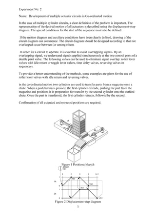
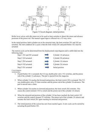
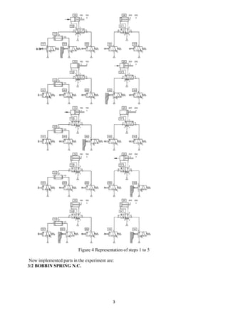
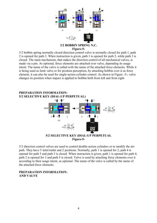

This document describes the development of a circuit to coordinate the motion of two cylinders to transfer parts. Roller lever valves with idle return are used as limit switches to detect the positions of the cylinders. The circuit operates in 5 steps: 1) cylinder 1 extends, 2) cylinder 2 extends, 3) cylinder 1 retracts, 4) cylinder 2 retracts, 5) return to initial position. New components introduced are 3/2 bobbin spring normally closed directional control valves, 5/2 selective key valves, and and/or logic valves.


