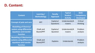
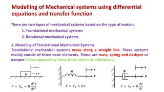
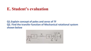
Marathwada Mitramandal’s
COLLEGE OF ENGINEERING
Karvenagar, Pune
Accredited with ‘A’ Grade by NAAC
Presentation
On
Subject: Control System Engineering
by
Mr. A. M. Suryawanshi
Department of Electrical Engineering
Unit 1: Basics of Control System
Session- 3/40
Concept of pole and zero, modeling of Electrical and
Mechanical systems (Only series linear and rotary motion)
using differential equations and transfer function
Session Plan
Outline:
A. Attendance
B. Review of the previous session
C. Learning Outcomes of the session
D. Content
E. Student’s evaluation
F. Preparation for next session
G. Wrap up
B. Review of previous session:
Tracking, Regulator system
Tracking and regulation refer to the ability of a control system to track/reject a given family of
reference/disturbance signals.
Feed forward system
The basic concept of feedforward control is to measure important disturbance variables and take
corrective action before they upset the process
Transfer function
A transfer function represents the relationship between the output signal of a control system and
the input signal, for all possible input values.
C. Learning Outcomes of the session:
- Understand concept of pole and zero
- Construct mathematical model of Electrical and Mechanical system using
differential equations and transfer function
D. Content:
Content
Learning /
Methodology
Faculty
Approach
Typical
Student
Activity
Skill/
Competency
Developed
Concept of pole and zero PPT
Explains/
Questions
Understands/A
nswers
Critical
thinking
Modelling of Electrical
system using differential
equations and transfer
function
Chalk and
Board/PPT
Explains/
Question
Understands/A
nswers
Problem
analysis
Modelling of Mechanical
systems using differential
equations and transfer
function
Chalk and
Board/PPT
Explains Understands
Problem
analysis
Concept of pole and zero
Poles and Zeros of a transfer function are the frequencies for which the value of
the denominator and numerator of transfer function becomes zero respectively.
Let the transfer function of a 2nd order system is defined as
G(s)= (s+1)/(s+2) (s+3)
Here, we can easily recognize the poles and zeroes.
Poles : These are those values of s when placed in denominator, the transfer
function tends to obtain infinite value. Here, the poles of the system are -2 and -3.
Zeroes : These are those values of s when placed in numerator makes the transfer
function 0. Here, the system have only 1 zero, ie, -1.
Introduction
- The frequencies for which the values of denominator and nominator become
zero in a transfer function are called Poles and Zeros.
- Poles and Zeros analyze the performance of a system and check the stability.
- The values of Poles and Zeros control the working of a system.
- Usually the numbers of Poles and Zeros are equal in a system and in some
cases number of Poles is greater.
Definition of Poles
Poles are the roots of the denominator of a transfer function. Let us take a simple
transfer function as an example:
𝑇 =
𝑁(𝑠)
𝐷(𝑠)
Where, N(s) and D(s) are simple polynomials
- Here Poles are the roots of D(s) and can be evaluated by taking D(s) = 0 and is
solved for s.
- Generally, the number of Poles is equal or greater than Zeros.
- When s approached a pole the value of denominator becomes Zero making the
value of transfer function reach infinity.
Definition of Zeros
- Similar to Poles, Zeros are the roots of nominator of a transfer function.
- For same above transfer function Zeros can be determined by taking N(s) = 0
and solving for s.
- The number of Zeros is lesser or equal to the Poles. Zeros mean that the output
at those frequencies is zero.
1. Definition:
• Poles are the roots of the denominator of a transfer function.
• Zeros are the roots of the nominator of a transfer function.
2. Determination:
• Poles are determined by equating D(s) with 0 and solving for s. Zeros are determined by
equating N(s) with 0 and solving for s.
3. Amount:
• The number of poles is always greater or equal to the Zeros.
• The numbers of Zeros are lesser or equal to Poles.
4. Determination of output:
• Poles in a transfer function explain that the output has reached to infinity.
• Whereas, the zeros in a transfer function indicate that the output has reached to zero.
Conclusion: -
The frequencies that turn nominator or denominator zero are called zero and poles of a
transfer function respectively. They determine the stability and working of a system.
Modelling of Electrical system using differential
equations and transfer function
Design of control system means finding the mathematical model when we know
the input and the output.
The following mathematical models are mostly used.
1. Differential equation model
2. Transfer function model
1. Differential Equation Model: -
Differential equation model is a time domain mathematical model of control
systems. Follow these steps for differential equation model.
a. Apply basic laws to the given control system.
b. Get the differential equation in terms of input and output by
eliminating the intermediate variable(s).
Example:
2. Transfer Function Model
- Transfer function model is an s-domain mathematical model of control
systems.
- The Transfer function of a Linear Time Invariant (LTI) system is defined as the
ratio of Laplace transform of output and Laplace transform of input by
assuming all the initial conditions are zero.
Example:
Answer
Modelling of Mechanical systems using differential
equations and transfer function
There are two types of mechanical systems based on the type of motion.
1. Translational mechanical systems
2. Rotational mechanical systems
1. Modeling of Translational Mechanical Systems
Translational mechanical systems move along a straight line. These systems
mainly consist of three basic elements. Those are mass, spring and dashpot or
damper. Force opposed by these three elements individually.
𝐹 = 𝐹𝑚 = 𝑀
𝑑2𝑥
𝑑𝑡2
𝐹 = 𝐹𝑘 = 𝐾𝑥 𝐹 = 𝐹𝑏 = 𝐵
𝑑𝑥
𝑑𝑡
2. Modeling of Rotational Mechanical Systems
- Rotational mechanical systems move about a fixed axis. These systems
mainly consist of three basic elements. Those are moment of inertia,
torsional spring and dashpot.
- If a torque is applied to a rotational mechanical system, then it is opposed by
opposing torques due to moment of inertia, elasticity and friction of the
system.
𝑇 = 𝑇𝑗 = 𝐽
𝑑2𝜃
𝑑𝑡2
𝑇 = 𝑇𝑘 = 𝐾𝜃 𝑇 = 𝑇𝑏 = 𝐵
𝑑𝜃
𝑑𝑡
E. Student’s evaluation
Q1.Explain concept of poles and zeros of TF
Q2. Find the transfer function of Mechanical rotational system
shown below
• Problems: Construct mathematical model of Electrical and Mechanical system
F. Preparation for Next Session:-
G. Wrap Up
In this lecture we have learned
Concept of pole and zero: -
Poles: These are those values of s when placed in denominator, the transfer function
tends to obtain infinite value. Here, the poles of the system are -2 and -3.
Zeroes: These are those values of s when placed in numerator makes the transfer
function 0. Here, the system have only 1 zero, ie, -1.
Modeling of Electrical and Mechanical systems (Only series linear and rotary motion)
using differential equations and transfer function: -
Design of control system means finding the mathematical model when we know the
input and the output.
The following mathematical models are mostly used.
1. Differential equation model
2. Transfer function model
There are two types of mechanical systems based on the type of motion.
1. Translational mechanical systems
2. Rotational mechanical systems

3. Concept of pole and zero.pptx

  • 1.
    Marathwada Mitramandal’s COLLEGE OFENGINEERING Karvenagar, Pune Accredited with ‘A’ Grade by NAAC Presentation On Subject: Control System Engineering by Mr. A. M. Suryawanshi Department of Electrical Engineering
  • 2.
    Unit 1: Basicsof Control System Session- 3/40 Concept of pole and zero, modeling of Electrical and Mechanical systems (Only series linear and rotary motion) using differential equations and transfer function Session Plan
  • 3.
    Outline: A. Attendance B. Reviewof the previous session C. Learning Outcomes of the session D. Content E. Student’s evaluation F. Preparation for next session G. Wrap up
  • 4.
    B. Review ofprevious session: Tracking, Regulator system Tracking and regulation refer to the ability of a control system to track/reject a given family of reference/disturbance signals. Feed forward system The basic concept of feedforward control is to measure important disturbance variables and take corrective action before they upset the process Transfer function A transfer function represents the relationship between the output signal of a control system and the input signal, for all possible input values.
  • 5.
    C. Learning Outcomesof the session: - Understand concept of pole and zero - Construct mathematical model of Electrical and Mechanical system using differential equations and transfer function
  • 6.
    D. Content: Content Learning / Methodology Faculty Approach Typical Student Activity Skill/ Competency Developed Conceptof pole and zero PPT Explains/ Questions Understands/A nswers Critical thinking Modelling of Electrical system using differential equations and transfer function Chalk and Board/PPT Explains/ Question Understands/A nswers Problem analysis Modelling of Mechanical systems using differential equations and transfer function Chalk and Board/PPT Explains Understands Problem analysis
  • 7.
    Concept of poleand zero Poles and Zeros of a transfer function are the frequencies for which the value of the denominator and numerator of transfer function becomes zero respectively. Let the transfer function of a 2nd order system is defined as G(s)= (s+1)/(s+2) (s+3) Here, we can easily recognize the poles and zeroes. Poles : These are those values of s when placed in denominator, the transfer function tends to obtain infinite value. Here, the poles of the system are -2 and -3. Zeroes : These are those values of s when placed in numerator makes the transfer function 0. Here, the system have only 1 zero, ie, -1.
  • 8.
    Introduction - The frequenciesfor which the values of denominator and nominator become zero in a transfer function are called Poles and Zeros. - Poles and Zeros analyze the performance of a system and check the stability. - The values of Poles and Zeros control the working of a system. - Usually the numbers of Poles and Zeros are equal in a system and in some cases number of Poles is greater.
  • 9.
    Definition of Poles Polesare the roots of the denominator of a transfer function. Let us take a simple transfer function as an example: 𝑇 = 𝑁(𝑠) 𝐷(𝑠) Where, N(s) and D(s) are simple polynomials - Here Poles are the roots of D(s) and can be evaluated by taking D(s) = 0 and is solved for s. - Generally, the number of Poles is equal or greater than Zeros. - When s approached a pole the value of denominator becomes Zero making the value of transfer function reach infinity.
  • 10.
    Definition of Zeros -Similar to Poles, Zeros are the roots of nominator of a transfer function. - For same above transfer function Zeros can be determined by taking N(s) = 0 and solving for s. - The number of Zeros is lesser or equal to the Poles. Zeros mean that the output at those frequencies is zero.
  • 11.
    1. Definition: • Polesare the roots of the denominator of a transfer function. • Zeros are the roots of the nominator of a transfer function. 2. Determination: • Poles are determined by equating D(s) with 0 and solving for s. Zeros are determined by equating N(s) with 0 and solving for s. 3. Amount: • The number of poles is always greater or equal to the Zeros. • The numbers of Zeros are lesser or equal to Poles. 4. Determination of output: • Poles in a transfer function explain that the output has reached to infinity. • Whereas, the zeros in a transfer function indicate that the output has reached to zero. Conclusion: - The frequencies that turn nominator or denominator zero are called zero and poles of a transfer function respectively. They determine the stability and working of a system.
  • 12.
    Modelling of Electricalsystem using differential equations and transfer function Design of control system means finding the mathematical model when we know the input and the output. The following mathematical models are mostly used. 1. Differential equation model 2. Transfer function model
  • 13.
    1. Differential EquationModel: - Differential equation model is a time domain mathematical model of control systems. Follow these steps for differential equation model. a. Apply basic laws to the given control system. b. Get the differential equation in terms of input and output by eliminating the intermediate variable(s). Example:
  • 14.
    2. Transfer FunctionModel - Transfer function model is an s-domain mathematical model of control systems. - The Transfer function of a Linear Time Invariant (LTI) system is defined as the ratio of Laplace transform of output and Laplace transform of input by assuming all the initial conditions are zero. Example: Answer
  • 15.
    Modelling of Mechanicalsystems using differential equations and transfer function There are two types of mechanical systems based on the type of motion. 1. Translational mechanical systems 2. Rotational mechanical systems 1. Modeling of Translational Mechanical Systems Translational mechanical systems move along a straight line. These systems mainly consist of three basic elements. Those are mass, spring and dashpot or damper. Force opposed by these three elements individually. 𝐹 = 𝐹𝑚 = 𝑀 𝑑2𝑥 𝑑𝑡2 𝐹 = 𝐹𝑘 = 𝐾𝑥 𝐹 = 𝐹𝑏 = 𝐵 𝑑𝑥 𝑑𝑡
  • 16.
    2. Modeling ofRotational Mechanical Systems - Rotational mechanical systems move about a fixed axis. These systems mainly consist of three basic elements. Those are moment of inertia, torsional spring and dashpot. - If a torque is applied to a rotational mechanical system, then it is opposed by opposing torques due to moment of inertia, elasticity and friction of the system. 𝑇 = 𝑇𝑗 = 𝐽 𝑑2𝜃 𝑑𝑡2 𝑇 = 𝑇𝑘 = 𝐾𝜃 𝑇 = 𝑇𝑏 = 𝐵 𝑑𝜃 𝑑𝑡
  • 17.
    E. Student’s evaluation Q1.Explainconcept of poles and zeros of TF Q2. Find the transfer function of Mechanical rotational system shown below
  • 18.
    • Problems: Constructmathematical model of Electrical and Mechanical system F. Preparation for Next Session:-
  • 19.
    G. Wrap Up Inthis lecture we have learned Concept of pole and zero: - Poles: These are those values of s when placed in denominator, the transfer function tends to obtain infinite value. Here, the poles of the system are -2 and -3. Zeroes: These are those values of s when placed in numerator makes the transfer function 0. Here, the system have only 1 zero, ie, -1. Modeling of Electrical and Mechanical systems (Only series linear and rotary motion) using differential equations and transfer function: - Design of control system means finding the mathematical model when we know the input and the output. The following mathematical models are mostly used. 1. Differential equation model 2. Transfer function model There are two types of mechanical systems based on the type of motion. 1. Translational mechanical systems 2. Rotational mechanical systems