1. The document provides guidance on creating working drawings and materials lists for prototyping designs, including types of drawings needed and how to construct them.
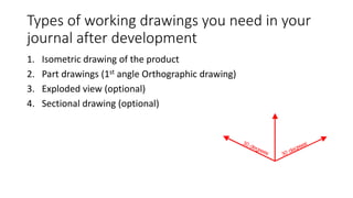
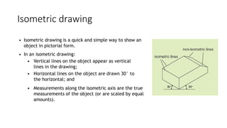
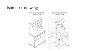
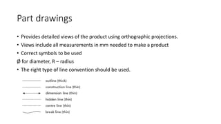
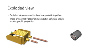
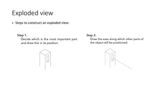
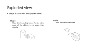
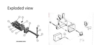
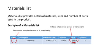
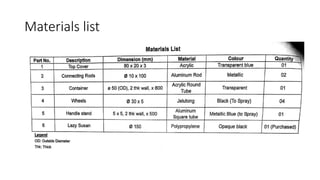
2. It describes how to make isometric drawings, orthographic part drawings, exploded views, and materials lists with relevant dimensions, part numbers, materials, and quantities.
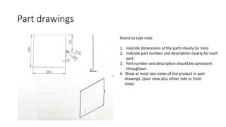
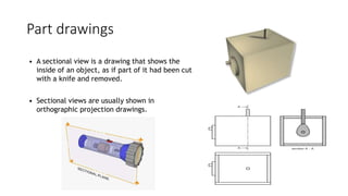
3. Instructions are given for including details, symbols, and views in the different types of technical drawings to fully communicate a product design.