Downloaded 73 times


![18
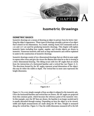
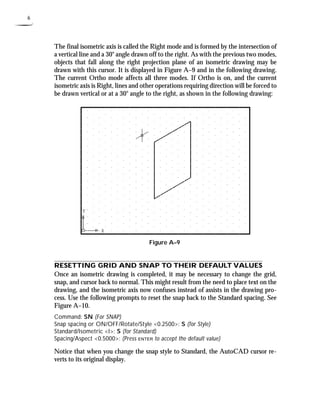
STEP 1
Set a new polar tracking angle of 30°
through the Polar Tracking tab of the
Drafting Settings dialog box in Figure A–
26A. Make the Object layer current. Then
use the LINE command to draw the object
in Figure A–26B. Notice, in the prompt
sequence, that the Direct Distance mode
is used because of the polar tracking angle
setting of 30°. Also, be sure to turn Polar
mode on by clicking on the POLAR but-ton
in the status bar.
Command: L (For LINE)
Specify first point: 5.50,0.75
Specify next point or [Undo]: (Move your
cursor up and to the right until the polar
angle tooltip reads 30 degrees and enter
3.25)
Specify next point or [Undo]: (Move your
cursor up and to the left until the polar
angle tooltip reads 150 degrees and enter
5.00)
Specify next point or [Close/Undo]:
(Move your cursor down and to the left
until the polar angle tooltip reads 210
degrees and enter 3.25)
Specify next point or [Close/Undo]: C
(To close the shape and exit the
command)
Figure A–26A
Figure A–26B](https://image.slidesharecdn.com/cha-141021031416-conversion-gate01/85/isometric-drawing-Chapter-18-320.jpg)
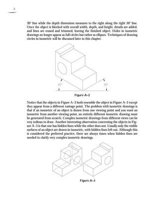
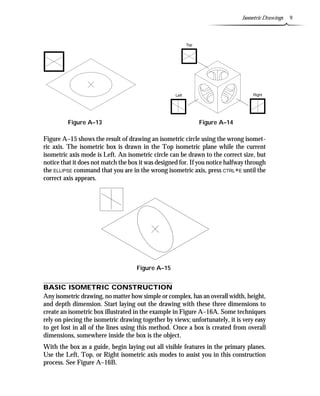
![Isometric Drawings 19
STEP 2
Copy the four lines drawn in Step 1 up a
distance of 2.50 units in the 90° direction
in Figure A–27.
Command: CP (For COPY)
Select objects: (Select lines “A”, “B”,”C”,
and “D”)
Select objects: (Press ENTER to continue)
Specify base point or displacement, or
[Multiple]: (Pick the endpoint of the line
at “A”)
Specify second point of displacement or
use first point as displacement:
(Move your cursor up until the polar
angle tooltip reads 90° and enter 2.50)
Figure A–27
STEP 3
Connect the top and bottom isometric
boxes with line segments, as shown in
Figure A–28. Draw one segment using
the LINE command. Repeat this process
using the LINE command at points “C” and
“D,” or use the COPY command and Mul-tiple
option to duplicate and form the re-maining
segments at “C” and “D.” Erase
the two dashed lines because they are not
visible in an isometric drawing.
Command: L (For LINE)
Specify first point: (Select the endpoint of
the line at “A”)
Specify next point or [Undo]: (Select the
endpoint of the line at “B”)
Specify next point or [Undo]: (Press
ENTER to exit this command)
Command: E (For ERASE)
Select objects: (Select the two dashed lines
in Figure A–28)
Select objects: (Press ENTER to execute this
command)
Figure A–28](https://image.slidesharecdn.com/cha-141021031416-conversion-gate01/85/isometric-drawing-Chapter-19-320.jpg)
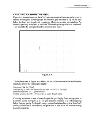
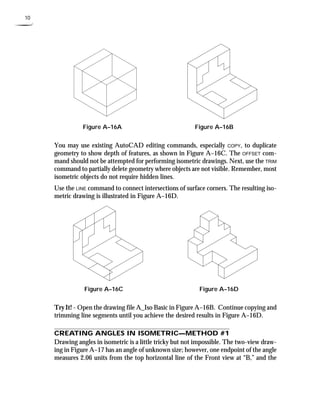
![20
STEP 4
Copy the two dashed lines in Figure A–29
a distance of 0.75 in the 210° direction.
Command: CP (For COPY)
Select objects: (Select the two dashed lines
in Figure A–29)
Select objects: (Press ENTER to continue)
Specify base point or displacement, or
[Multiple]: (Select the endpoint at “A”)
Specify second point of displacement or
use first point as displacement:
(Move your cursor down and to the left
until the polar angle tooltip reads 210°
and enter 0.75)
Figure A–29
STEP 5
Copy the two dashed lines in Figure A–30
a distance of 0.75 in the 90° direction.
This forms the base of the plate.
Command: CP (For COPY)
Select objects: (Select the two dashed lines
in Figure A–30)
Select objects: (Press ENTER to continue)
Specify base point or displacement, or
[Multiple]: (Select the endpoint at “A”)
Specify second point of displacement or
use first point as displacement:
(Move your cursor up until the polar
angle tooltip reads 90°and enter 0.75) Figure A–30](https://image.slidesharecdn.com/cha-141021031416-conversion-gate01/85/isometric-drawing-Chapter-20-320.jpg)
![Isometric Drawings 21
Figure A–31
STEP 6
Copy the dashed line in Figure A–31 a
distance of 0.75 in the 330° direction.
Command: CP (For COPY)
Select objects: (Select the dashed line in
Figure A–31)
Select objects: (Press ENTER to continue)
Specify base point or displacement, or
[Multiple]: (Select the endpoint at “A”)
Specify second point of displacement or
use first point as displacement:
(Move your cursor down and to the right
until the polar angle tooltip reads
330°and enter 0.75)
STEP 7
Use the FILLET command to place a cor-ner
between the two dashed lines at “A”
and “B” and at “C” and “D” in Figure
A–32. Set the fillet radius to a value of 0
to accomplish this.
Command: F (For FILLET)
Current settings: Mode = TRIM, Radius =
0.50
Select first object or [Polyline/Radius/
Trim]: R (For Radius)
Specify fillet radius 0.50: 0
Select first object or [Polyline/Radius/
Trim]: (Select line “A”)
Select second object: (Select line “B”)
Command: F (For FILLET)
Current settings: Mode = TRIM, Radius =
0.00
Select first object or [Polyline/Radius/
Trim]: (Select line “C”)
Select second object: (Select line “D”)
Figure A–32](https://image.slidesharecdn.com/cha-141021031416-conversion-gate01/85/isometric-drawing-Chapter-21-320.jpg)
![22
STEP 8
Copy the dashed line in Figure A–33 to
begin forming the top of the base.
Command: CP (For COPY)
Select objects: (Select the dashed line in
Figure A–33)
Select objects: (Press ENTERto continue)
Specify base point or displacement, or
[Multiple]: (Select the endpoint at “A”)
Specify second point of displacement or
use first point as displacement:
(Select the endpoint at “B”)
Figure A–33
STEP 9
Copy the dashed line in Figure A–34.
This forms the base of the plate.
Command: CP (For COPY)
Select objects: (Select the dashed line in
Figure A–34)
Select objects: (Press ENTER to continue)
Specify base point or displacement, or
[Multiple]: (Select the endpoint at “A”)
Specify second point of displacement or
use first point as displacement:
(Select the endpoint at “B”)
Figure A–34](https://image.slidesharecdn.com/cha-141021031416-conversion-gate01/85/isometric-drawing-Chapter-22-320.jpg)
![Isometric Drawings 23
STEP 10
Use the TRIM command to clean up the
excess lines in Figure A–35.
Command: TR (For TRIM)
Current settings: Projection=UCS
Edge=None
Select cutting edges ...
Select objects: (Select the three dashed
lines shown in Figure A–35)
Select objects: (Press ENTER to continue)
Select object to trim or shift-select to
extend or [Project/Edge/Undo]: (Select
the inclined line at “A”)
Select object to trim or shift-select to
extend or [Project/Edge/Undo]: (Select
the inclined line at “B”)
Select object to trim or shift-select to
extend or [Project/Edge/Undo]: (Select
the inclined line at “C”)
Select object to trim or shift-select to
extend or [Project/Edge/Undo]: (Press
ENTER to exit this command)
Figure A–35
STEP 11
Your display should be similar to Figure
A–36.
Figure A–36
STEP 12
Copy the dashed line in Figure A–37 a
distance of 1.12 units in the 90° direc-tion.
Command: CP (For COPY)
Select objects: (Select the dashed line in
Figure A–37)
Select objects: (Press ENTER to continue)
Specify base point or displacement, or
[Multiple]: (Select the endpoint at “A”)
Specify second point of displacement or
use first point as displacement:
(Move your cursor up until the polar
angle tooltip reads 90°and enter 1.12) Figure A–37](https://image.slidesharecdn.com/cha-141021031416-conversion-gate01/85/isometric-drawing-Chapter-23-320.jpg)
![24
STEP 13
As shown in Figure A–38, copy the
dashed line at “A” to new positions at “B”
and “C.” Then delete the line at “A” us-ing
the ERASE command.
Command: CP (For COPY)
Select objects: (Select the dashed line in
Figure A–38)
Select objects: (Press ENTER to continue)
Specify base point or displacement, or
[Multiple]: M (For Multiple)
Specify base point: (Select the endpoint at
“A”)
Specify second point of displacement or
use first point as displacement:
(Select the endpoint at “B”)
Specify second point of displacement or
use first point as displacement:
(Select the endpoint at “C”)
Specify second point of displacement or
use first point as displacement:
(Press ENTER to exit this command)
Command: E (For ERASE)
Select objects: (Select the dashed line at
“A”)
Select objects: (Press ENTER to execute this
command)
Figure A–38
STEP 14
Use the TRIM command to clean up the
excess lines in Figure A–39.
Command: TR (For TRIM)
Current settings: Projection=UCS
Edge=None
Select cutting edges ...
Select objects: (Select the two dashed lines
in Figure A–39)
Select objects: (Press ENTERto continue)
Select object to trim or shift-select to
extend or [Project/Edge/Undo]: (Select
the vertical line at “A”)
Select object to trim or shift-select to
extend or [Project/Edge/Undo]: (Select
the vertical line at “B”)
Select object to trim or shift-select to
extend or [Project/Edge/Undo]: (Select
the inclined line at “C”)
Figure A–39
Select object to trim or shift-select to
extend or [Project/Edge/Undo]: (Press
ENTER to exit this command)](https://image.slidesharecdn.com/cha-141021031416-conversion-gate01/85/isometric-drawing-Chapter-24-320.jpg)
![Isometric Drawings 25
STEP 15
Use the COPY command to duplicate the
dashed line in Figure A–40 from the end-point
of “A” to the endpoint at “B.”
Command: CP (For COPY)
Select objects: (Select the dashed line in
Figure A–40)
Select objects: (Press ENTER to continue)
Specify base point or displacement, or
[Multiple]: (Select the endpoint at “A”)
Specify second point of displacement or
use first point as displacement:
(Select the endpoint at “B”) Figure A–40
STEP 16
Use the COPY command to duplicate the
dashed line in Figure A–41 from the end-point
of “A” to the endpoint at “B.”
Command: CP (For COPY)
Select objects: (Select the dashed line in
Figure A–41)
Select objects: (Press ENTER to continue)
Specify base point or displacement, or
[Multiple]: (Select the endpoint at “A”)
Specify second point of displacement or
use first point as displacement:
(Select the endpoint at “B”) Figure A–41](https://image.slidesharecdn.com/cha-141021031416-conversion-gate01/85/isometric-drawing-Chapter-25-320.jpg)
![26
STEP 17
Use the LINE command to connect the
endpoints of the segments at “A” and “B”
in Figure A–42.
Command: L (For LINE)
Specify first point: (Select the endpoint at
“A”)
Specify next point or [Undo]: (Select the
endpoint at “B”)
Specify next point or [Undo]: (Press
ENTER to exit this command) Figure A–42
STEP 18
Use the COPY command to duplicate the
dashed line in Figure A–43 from the
endpoint of “A” a distance of 0.50 units
in the 210° direction. This value begins
the outline of the rectangular hole
through the object.
Command: CP (For COPY)
Select objects: (Select the dashed line in
Figure A–43)
Select objects: (Press ENTER to continue)
Specify base point or displacement, or
[Multiple]: (Select the endpoint at “A”)
Specify second point of displacement or
use first point as displacement:
(Move your cursor down and to the left
until the polar angle tooltip reads 210°
and enter 0.50)
Figure A–43](https://image.slidesharecdn.com/cha-141021031416-conversion-gate01/85/isometric-drawing-Chapter-26-320.jpg)
![Isometric Drawings 27
STEP 19
Use the COPY command to duplicate the
dashed line in Figure A–44 from the
endpoint of “A” a distance of 0.50 in the
330° direction.
Command: CP (For COPY)
Select objects: (Select the dashed line in
Figure A–44)
Select objects: (Press ENTER to continue)
Specify base point or displacement, or
[Multiple]: (Select the endpoint at “A”)
Specify second point of displacement or
use first point as displacement:
(Move your cursor down and to the right
until the polar angle tooltip reads 330°
and enter 0.50)
Figure A–44
STEP 20
Use the COPY command to duplicate the
dashed line in Figure A–45 from the
endpoint of “A” a distance of 0.50 in the
30° direction.
Command: CP (For COPY)
Select objects: (Select the dashed line in
Figure A–45)
Select objects: (Press ENTER to continue)
Specify base point or displacement, or
[Multiple]: (Select the endpoint at “A”)
Specify second point of displacement or
use first point as displacement:
(Move your cursor up and to the right
until the polar angle tooltip reads 30°
and enter 0.50)
Figure A–45](https://image.slidesharecdn.com/cha-141021031416-conversion-gate01/85/isometric-drawing-Chapter-27-320.jpg)
![28
STEP 21
Use the COPY command to duplicate the
dashed line in Figure A–46 from the
endpoint of “A” a distance of 0.50 in the
150° direction.
Command: CP (For COPY)
Select objects: (Select the dashed line in
Figure A–46)
Select objects: (Press ENTER to continue)
Specify base point or displacement, or
[Multiple]: (Select the endpoint at “A”)
Specify second point of displacement or
use first point as displacement:
(Move your cursor up and to the right
until the polar angle tooltip reads 150°
and enter 0.50)
Figure A–46
STEP 22
Use the FILLET command with a radius of
0 to corner the four dashed lines in Fig-ure
A–47. Use the MULTIPLE command to
remain in the FILLET command. To exit
the FILLET command prompts, press ESC
to cancel the command when finished.
Command: MULTIPLE
Enter command name to repeat: F (For
FILLET)
Current settings: Mode = TRIM, Radius =
0.0000
Select first object or [Polyline/Radius/
Trim]: (Select the line at “A”)
Select second object: (Select the line at “B”)
FILLET
Current settings: Mode = TRIM, Radius =
0.0000
Select first object or [Polyline/Radius/
Trim]: (Select the line at “B”)
Select second object: (Select the line at “C”)
FILLET
Current settings: Mode = TRIM, Radius =
0.0000
Select first object or [Polyline/Radius/
Trim]: (Select the line at “C”)
Select second object: (Select the line at “D”)
FILLET
Current settings: Mode = TRIM, Radius =
0.0000
Select first object or [Polyline/Radius/
Trim]: (Select the line at “D”)
Select second object: (Select the line at “A”)
FILLET
Current settings: Mode = TRIM, Radius =
0.0000
Select first object or [Polyline/Radius/
Trim]: (Press ESC to cancel this
command)
Figure A–47](https://image.slidesharecdn.com/cha-141021031416-conversion-gate01/85/isometric-drawing-Chapter-28-320.jpg)
![Isometric Drawings 29
STEP 23
Use the COPY command to duplicate the
dashed line in Figure A–48. This will
begin forming the thickness of the base
inside the rectangular hole.
Command: CP (For COPY)
Select objects: (Select the dashed line in
Figure A–48)
Select objects: (Press ENTER to continue)
Specify base point or displacement, or
[Multiple]: (Select the endpoint at “A”)
Specify second point of displacement or
use first point as displacement:
(Select the endpoint at “B”)
Figure A–48
STEP 24
Use the COPY command to duplicate the
dashed lines in Figure A–49. These lines
form the inside surfaces to the rectangu-lar
hole.
Command: CP (For COPY)
Select objects: (Select the dashed lines in
Figure A–49)
Select objects: (Press ENTER to continue)
Specify base point or displacement, or
[Multiple]: (Select the endpoint at “A”)
Specify second point of displacement or
use first point as displacement:
(Select the endpoint at “B”)
Figure A–49](https://image.slidesharecdn.com/cha-141021031416-conversion-gate01/85/isometric-drawing-Chapter-29-320.jpg)
![30
STEP 25
Use the TRIM command to clean up excess
lines in Figure A–50.
Command: TR (For TRIM)
Current settings: Projection=UCS
Edge=None
Select cutting edges ...
Select objects: (Select the two dashed lines
in Figure A–50)
Select objects: (Press ENTER to continue)
Select object to trim or shift-select to
extend or [Project/Edge/Undo]: (Select
the line at “A”)
Select object to trim or shift-select to
extend or [Project/Edge/Undo]: (Select
the line at “B”)
Select object to trim or shift-select to
extend or [Project/Edge/Undo]: (Press
ENTER to exit this command)
Figure A–50
STEP 26
The completed isometric is illustrated
in Figure A–51. This drawing may be
dimensioned with the Oblique option of the
DIMEDIT command. Consult your instructor
if this next step is necessary.
Figure A–51](https://image.slidesharecdn.com/cha-141021031416-conversion-gate01/85/isometric-drawing-Chapter-30-320.jpg)

![32
STEP 1
Make the Object layer current. Then set
the SNAP-Style option to Isometric with
a vertical spacing of 0.25 units. Press
CTRL+E or F5 to switch to the Top
Isoplane mode. Use the LINE command to
draw the rectangular isometric box rep-resenting
the total depth of the object
along with the center-to-center distance
of the holes and arcs that will be placed
in the next step. See Figure A–53.
Command: SN (For SNAP)
Specify snap spacing or [ON/OFF/Aspect/
Rotate/Style/Type] 0.50: S (For
Style)
Enter snap grid style [Standard/Isometric]
S: I (For Isometric)
Specify vertical spacing 0.50: 0.25
Command: (Press CTRL+E to switch to the
Top Isoplane mode)
Command: L (For LINE)
Specify first point: 6.00,0.50
Specify next point or [Undo]: (Move your
cursor up and to the right and enter
5.00)
Specify next point or [Undo]: (Move your
cursor up and to the left and enter 3.00)
Specify next point or [Close/Undo]:
(Move your cursor down and to the left
and enter 5.00)
Specify next point or [Close/Undo]: C
(To close the shape and exit the
command)
Figure A–53
STEP 2
While in the Top Isoplane mode, use the
ELLIPSE command to draw two isometric
ellipses of 0.75 and 1.50 radii each in Fig-ure
A–54. Identify the midpoint of the
inclined line at “A” as the center of the
first ellipse. To identify the center of the
second ellipse, use the @ option, which
stands for “last point” and will identify the
center of the small circle as the same cen-ter
as the large circle.
Command: EL (For ELLIPSE)
Specify axis endpoint of ellipse or [Arc/
Center/Isocircle]: I (For Isocircle)
Specify center of isocircle: Mid
of (Pick the midpoint of the line at “A”)
Specify radius of isocircle or [Diameter]:
0.75
Command: EL (For ELLIPSE)
Specify axis endpoint of ellipse or [Arc/
Center/Isocircle]: I (For Isocircle)
Specify center of isocircle: @ (For the last
point)
Specify radius of isocircle or [Diameter]:
1.50
Figure A–54](https://image.slidesharecdn.com/cha-141021031416-conversion-gate01/85/isometric-drawing-Chapter-32-320.jpg)
![Isometric Drawings 33
STEP 3
Copy both ellipses from the endpoint
of the inclined line at “A” to the end-point
of the inclined line at “B” in Fig-ure
A–55. Be sure Snap is turned off.
Command: CP (For COPY)
Select objects: (Select both ellipses in
Figure A–55)
Select objects: (Press ENTER to continue)
Specify base point or displacement, or
[Multiple]: (Select the endpoint at “A”)
Specify second point of displacement or
use first point as displacement:
(Select the endpoint at “B”)
Figure A–55
STEP 4
Use the TRIM command to delete segments
of the ellipses in Figure A–56.
Command: TR (For TRIM)
Current settings: Projection=UCS
Edge=None
Select cutting edges ...
Select objects: (Select dashed lines “A”
and “B”)
Select objects: (Press ENTER to continue)
Select object to trim or shift-select to
extend or [Project/Edge/Undo]: (Select
the ellipse at “C”)
Select object to trim or shift-select to
extend or [Project/Edge/Undo]: (Select
the ellipse at “D”)
Select object to trim or shift-select to
extend or [Project/Edge/Undo]: (Press
ENTER to exit this command)
Figure A–56](https://image.slidesharecdn.com/cha-141021031416-conversion-gate01/85/isometric-drawing-Chapter-33-320.jpg)
![34
STEP 5
Copy all objects in Figure A–57 up the
distance of 0.25 units to form the bottom
base of the hanger. Pressing CTRL+E or
F5 can activate the Right Isoplane mode.
Command: (Press CTRL+E To switch to
the Right Isoplane mode)
Right Isoplane
Command: CP (For COPY)
Select objects: (Select all objects in Figure
A–57)
Select objects: (Press ENTER to continue)
Specify base point or displacement, or
[Multiple]: (Select the endpoint at “A”)
Specify second point of displacement or
use first point as displacement:
(Move your cursor up and enter a value
of 0.25)
Figure A–57
STEP 6
Use the ERASE command to delete the
three dashed lines in Figure A–58. These
lines are not visible from this point of view
and should be erased.
Command: E (For ERASE)
Select objects: (Select the three dashed
lines in Figure A–58)
Select objects: (Press ENTERto execute this
command)
Figure A–58](https://image.slidesharecdn.com/cha-141021031416-conversion-gate01/85/isometric-drawing-Chapter-34-320.jpg)
![Isometric Drawings 35
STEP 7
Your display should appear similar to the
illustration in Figure A–59. Begin par-tially
deleting other objects to show only
visible features of the isometric drawing.
Check that the snap has been turned off
to better assist in the next series of opera-tions.
The next few steps refer to the area
outlined in Figure A–59. Use the ZOOM-Window
option to magnify this area.
Command: Z (For ZOOM)
Specify corner of window, enter a scale
factor (nX or nXP), or
[All/Center/Dynamic/Extents/Previous/
Scale/Window] real time: (Pick a
point at “A”)
Specify opposite corner: (Pick a point
at “B”)
Figure A–59
STEP 8
Carefully draw a line tangent to both el-lipses.
Use the OSNAP-Quadrant option
to assist in constructing the line. See Fig-ure
A–60.
Command: L (For LINE)
Specify first point: Qua
of (Select the quadrant at “A”)
Specify next point or [Undo]: (Pick the
polar intersection at “B”)
Specify next point or [Undo]: (Press
ENTER to exit this command) Figure A–60](https://image.slidesharecdn.com/cha-141021031416-conversion-gate01/85/isometric-drawing-Chapter-35-320.jpg)
![36
STEP 9
Use the TRIM command, select the short
dashed line as the cutting edge, and select
the arc segment in Figure A–61 to trim.
Command: TR (For TRIM)
Current settings: Projection=UCS
Edge=None
Select cutting edges ...
Select objects: (Select the dashed line at “A”)
Select objects: (Press ENTER to continue)
Select object to trim or shift-select to
extend or [Project/Edge/Undo]: (Select
the ellipse at “B”)
Select object to trim or shift-select to
extend or [Project/Edge/Undo]: (Press
ENTER to exit this command)
Figure A–61
STEP 10
The completed operation is in Figure A–62.
Use ZOOM command and the Previous option
to return to the previous display.
Command: Z (For ZOOM)
Specify corner of window, enter a scale
factor (nX or nXP), or
[All/Center/Dynamic/Extents/Previous/
Scale/Window] real time: P (For
Previous) Figure A–62
STEP 11
Use ZOOM-Window to magnify the
right half of the base in Figure A–63. Pre-pare
to construct the tangent edge to the
object using the procedure in Step 8.
Command: Z (For ZOOM)
Specify corner of window, enter a scale
factor (nX or nXP), or
[All/Center/Dynamic/Extents/Previous/
Scale/Window] real time: (Pick a
point at “A”)
Specify opposite corner: (Pick a point at “B”) Figure A–63](https://image.slidesharecdn.com/cha-141021031416-conversion-gate01/85/isometric-drawing-Chapter-36-320.jpg)
![Isometric Drawings 37
STEP 12
Follow the same procedure as in Step 8
to construct a line from the quadrant point
on the top ellipse to the polar intersec-tion
on the bottom ellipse. Then use the
TRIM command in Step 9 to clean up any
excess objects. Use the ERASE command
to delete any elliptical arc segments that
may have been left untrimmed. (See Fig-ure
A–64.) Figure A–64
STEP 13
Zoom to the Previous display. Use the
TRIM command to partially delete the el-lipses
in Figure A–65 to expose the thick-ness
of the base.
Command: TR (For TRIM)
Current settings: Projection=UCS
Edge=None
Select cutting edges ...
Select objects: (Select dashed ellipses “A”
and “B”)
Select objects: (Press ENTER to continue)
Select object to trim or shift-select to
extend or [Project/Edge/Undo]: (Select
the lower ellipse at “C”)
Select object to trim or shift-select to
extend or [Project/Edge/Undo]: (Select
the lower ellipse at “D”)
Select object to trim or shift-select to
extend or [Project/Edge/Undo]: (Press
ENTER to exit this command)
Figure A–65](https://image.slidesharecdn.com/cha-141021031416-conversion-gate01/85/isometric-drawing-Chapter-37-320.jpg)
![38
STEP 14
Use the COPY command to duplicate the
bottom base and form the upper plate of
the hanger as shown in Figure A–66. Copy
the base a distance of 4 units straight up.
Command: CP (For COPY)
Select objects: (Select all dashed objects in
Figure A–66)
Select objects: (Press ENTER to continue)
Specify base point or displacement, or
[Multiple]: (Select the endpoint of the
ellipse at “A”)
Specify second point of displacement or
use first point as displacement:
(Move your cursor up and enter a value
of 4.00) Figure A–66
STEP 15
Use the COPY command to duplicate the
inclined line at “A” the distance of 2.50 units
to form the line represented by a series of
dashes in Figure A–67. This line happens
to be located at the center of the object.
Command: CP (For COPY)
Select objects: (Select the line at “A”)
Select objects: (Press ENTER to continue)
Specify base point or displacement, or
[Multiple]: (Select the endpoint at “A”)
Specify second point of displacement or
use first point as displacement:
(Move your cursor up and to the right
and enter 2.50)
Figure A–67](https://image.slidesharecdn.com/cha-141021031416-conversion-gate01/85/isometric-drawing-Chapter-38-320.jpg)
![Isometric Drawings 39
STEP 16
Duplicate the line represented by dashes
in Figure A–68 to form the two inclined
lines at “B” and “C.” These lines will be-gin
the construction of the sides of the
hanger. Use the COPY command along with
the Multiple option to accomplish this.
Command: CP (For COPY)
Select objects: (Select the dashed line in
Figure A–68)
Select objects: (Press ENTER to continue)
Specify base point or displacement, or
[Multiple]: M (For Multiple)
Specify base point: (Select the endpoint at
“A”)
Specify second point of displacement or
use first point as displacement:
(Move your cursor up and to the right
and enter 1.25)
Specify second point of displacement or
use first point as displacement:
(Move your cursor down and to the left
and enter 1.25)
Figure A–68
Specify second point of displacement or
use first point as displacement:
(Press ENTER to exit this command)
STEP 17
Use the COPY command to duplicate the
two dashed lines in Figure A–69 straight
up at a distance of 3.75 units. Use the
Polar coordinate mode to accomplish this.
Make sure the Polar mode is turned On.
Command: CP (For COPY)
Select objects: (Select both dashed lines in
Figure A–69)
Select objects: (Press ENTER to continue)
Specify base point or displacement, or
[Multiple]: (Select the endpoint at “A”)
Specify second point of displacement or
use first point as displacement: (Pick
the Polar Intersection at “B”) Figure A–69](https://image.slidesharecdn.com/cha-141021031416-conversion-gate01/85/isometric-drawing-Chapter-39-320.jpg)
![40
STEP 18
Use the LINE command along with the
OSNAP-Endpoint option to draw a line
from endpoint “A” to endpoint “B” in
Figure A–70.
Command: L (For LINE)
Specify first point: (Select the endpoint at
“A”)
Specify next point or [Undo]: (Select the
endpoint at “B”)
Specify next point or [Undo]: (Press
ENTER to exit this command)
Figure A–70
STEP 19
Use the COPY command and the Multiple
option to copy the dashed line at “A” to
“B,” “C,” and “D” in Figure A–71.
Command: CP (For COPY)
Select objects: (Select the dashed line in
Figure A–71)
Select objects: (Press ENTER to continue)
Specify base point or displacement, or
[Multiple]: M (For Multiple)
Specify base point: (Select the endpoint of
the vertical line at “A”)
Specify second point of displacement or
use first point as displacement:
(Select the endpoint of the line at “B”)
Specify second point of displacement or
use first point as displacement:
(Select the endpoint of the line at “C”)
Specify second point of displacement or
use first point as displacement:
(Select the endpoint of the line at “D”)
Specify second point of displacement or
use first point as displacement:
(Press ENTER to exit this command)
Figure A–71](https://image.slidesharecdn.com/cha-141021031416-conversion-gate01/85/isometric-drawing-Chapter-40-320.jpg)
![Isometric Drawings 41
STEP 20
Use the ERASE command to delete all
lines represented as dashed lines in Fig-ure
A–72.
Command: E (For ERASE)
Select objects: (Select all dashed objects in
Figure A–72)
Select objects: (Press ENTER to execute this
command)
Figure A–72
STEP 21
Use the TRIM command to partially delete
the vertical line in Figure A–73. The seg-ment
to be deleted is hidden and not
shown in an isometric drawing.
Command: TR (For TRIM)
Current settings: Projection=UCS
Edge=None
Select cutting edges ...
Select objects: (Select the dashed objects at
“A” and “B”)
Select objects: (Press ENTER to continue)
Select object to trim or shift-select to
extend or [Project/Edge/Undo]: (Select
the vertical line at “C”)
Select object to trim or shift-select to
extend or [Project/Edge/Undo]: (Press
ENTER to exit this command)
Figure A–73](https://image.slidesharecdn.com/cha-141021031416-conversion-gate01/85/isometric-drawing-Chapter-41-320.jpg)
![42
STEP 22
Use the TRIM command to partially delete
the vertical line in Figure A–74. The seg-ment
to be deleted is hidden and not
shown in an isometric drawing.
Command: TR (For TRIM)
Current settings: Projection=UCS
Edge=None
Select cutting edges ...
Select objects: (Select the dashed elliptical
arc at “A”)
Select objects: (Press ENTER to continue)
Select object to trim or shift-select to
extend or [Project/Edge/Undo]: (Select
the vertical line at “B”)
Select object to trim or shift-select to
extend or [Project/Edge/Undo]: (Press
ENTER to exit this command)
Figure A–74
STEP 23
Use the TRIM command to partially delete
the inclined line in Figure A–75.
Command: TR (For TRIM)
Current settings: Projection=UCS
Edge=None
Select cutting edges ...
Select objects: (Select the dashed lines “A”
and “B”)
Select objects: (Press ENTER to continue)
Select object to trim or shift-select to
extend or [Project/Edge/Undo]: (Select
the line at “C”)
Select object to trim or shift-select to
extend or [Project/Edge/Undo]: (Select
the line at “D”)
Select object to trim or shift-select to
extend or [Project/Edge/Undo]: (Press
ENTER to exit this command)
Figure A–75](https://image.slidesharecdn.com/cha-141021031416-conversion-gate01/85/isometric-drawing-Chapter-42-320.jpg)
![Isometric Drawings 43
STEP 24
Use the TRIM command to partially delete
the objects in Figure A–76. The segments
to be deleted are hidden and not shown
in an isometric drawing. Use ERASE to
delete any leftover elliptical arc segments.
Command: TR (For TRIM)
Current settings: Projection=UCS
Edge=None
Select cutting edges ...
Select objects: (Select the dashed lines “A”
and “B”)
Select objects: (Press ENTER to continue)
Select object to trim or shift-select to
extend or [Project/Edge/Undo]: (Select
the line at “C”)
Select object to trim or shift-select to
extend or [Project/Edge/Undo]: (Select
the elliptical arc at “D”)
Select object to trim or shift-select to
extend or [Project/Edge/Undo]: (Select
the ellipse at “E”)
Select object to trim or shift-select to
extend or [Project/Edge/Undo]: (Select
the elliptical arc at “F”)
Select object to trim or shift-select to
extend or [Project/Edge/Undo]: (Press
ENTER to exit this command)
Figure A–76
STEP 25
The completed isometric appears in Fig-ure
A–77. This drawing may be dimen-sioned
with the Oblique option of the
DIMEDIT command. Consult your instruc-tor
if this next step is necessary.
Figure A–77](https://image.slidesharecdn.com/cha-141021031416-conversion-gate01/85/isometric-drawing-Chapter-43-320.jpg)


This document provides instructions on creating isometric drawings in AutoCAD. It explains that isometric drawings use 2D representations tilted at 30 degree angles to give the illusion of 3D. It also covers how to set up an isometric grid, use the different isometric axes modes, construct angles and circles in isometric, and provides steps for basic isometric object construction.


