Downloaded 115 times
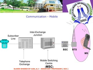
![How / when diversity is created ? Diversity is created when these signals are separated in the receiver Examples: RAKE receiver - - separates paths by delay [PATH DIVERSITY] Multi beam antenna - - separates paths by angle [ANGLE DIVERSITY]](https://image.slidesharecdn.com/wmcdiversity-120122133114-phpapp02/85/RADIATION-PROPAGATION-diversity-9-320.jpg)
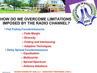
![Another way to create diversity: change the relative phases of the multi path signals Examples: Identical antennas, slightly different locations [ SPACE DIVERSITY ] Same signal received on different RF carriers [ FREQUENCY DIVERSITY ]. Required carrier separation depends inversely on delay spread](https://image.slidesharecdn.com/wmcdiversity-120122133114-phpapp02/85/RADIATION-PROPAGATION-diversity-26-320.jpg)
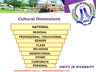
![Still other ways to generate diversity: Dual polarized antennas [ POLARIZATION DIVERSITY ]](https://image.slidesharecdn.com/wmcdiversity-120122133114-phpapp02/85/RADIATION-PROPAGATION-diversity-27-320.jpg)
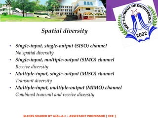
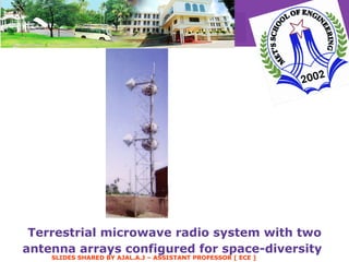
![1] Space diversity The signal is transferred over several different propagation paths. In the case of wired transmission, this can be achieved by transmitting via multiple wires. In the case of wireless transmission, it can be achieved by antenna diversity using multiple transmitter antennas (transmit diversity) and/or multiple receiving antennas (reception diversity). In the latter case, a diversity combining technique is applied before further signal processing takes place.](https://image.slidesharecdn.com/wmcdiversity-120122133114-phpapp02/85/RADIATION-PROPAGATION-diversity-32-320.jpg)
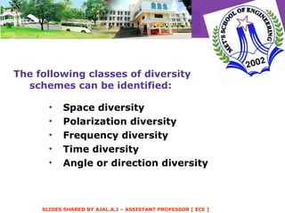
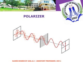
![2] Polarization diversity Polarization diversity : Multiple versions of a signal are transmitted and received via antennas with different polarization. A diversity combining technique is applied on the receiver side.](https://image.slidesharecdn.com/wmcdiversity-120122133114-phpapp02/85/RADIATION-PROPAGATION-diversity-33-320.jpg)
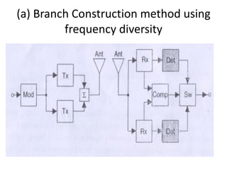
![3] Frequency diversity Frequency diversity: The signal is transferred using several frequency channels or spread over a wide spectrum that is affected by frequency-selective fading. Middle-late 20th century microwave radio relay lines often used several regular wideband radio channels, and one protection channel for automatic use by any faded channel. Later examples include: OFDM modulation in combination with subcarrier interleaving and forward error correction Spread spectrum, for example frequency hopping or DS-CDMA.](https://image.slidesharecdn.com/wmcdiversity-120122133114-phpapp02/85/RADIATION-PROPAGATION-diversity-35-320.jpg)
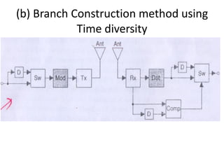
![4] Time diversity Time diversity : Multiple versions of the same signal are transmitted at different time instants.](https://image.slidesharecdn.com/wmcdiversity-120122133114-phpapp02/85/RADIATION-PROPAGATION-diversity-36-320.jpg)
![Thank you for you patient attention Mail: [email_address]](https://image.slidesharecdn.com/wmcdiversity-120122133114-phpapp02/85/RADIATION-PROPAGATION-diversity-64-320.jpg)

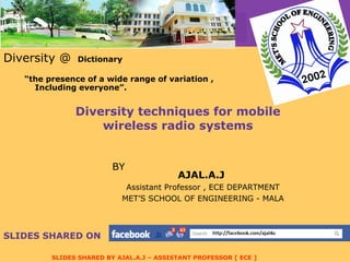
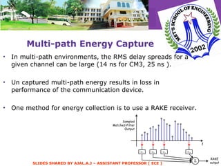
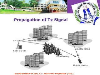
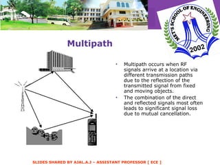
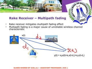
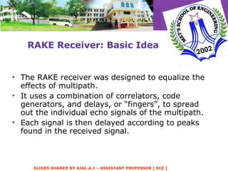
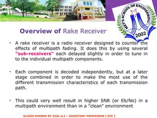
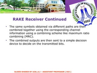
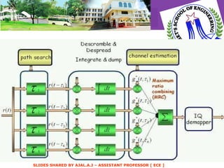
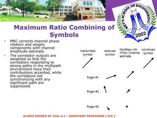
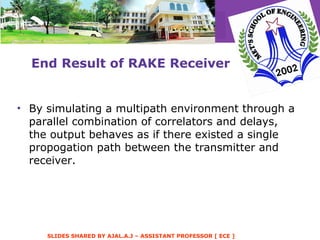
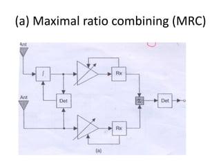
1) Diversity techniques in mobile wireless systems take advantage of multiple propagation paths to improve reliability by creating independent fading channels and combining the signals. 2) Common diversity techniques include space, time, frequency, angle, and polarization diversity which are created using multiple antennas, frequency bands, time slots, antenna angles or polarizations. 3) A Rake receiver is used to implement path diversity, capturing multipath signal energy with fingers tuned to peaks in the delay profile and maximizing ratio combining.