Downloaded 673 times


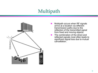
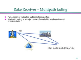


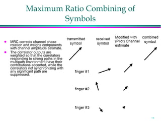


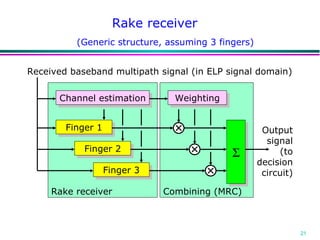
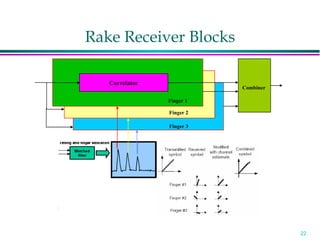

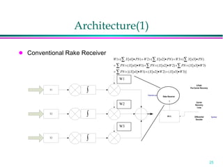
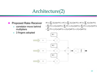

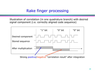

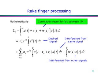


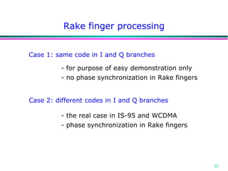

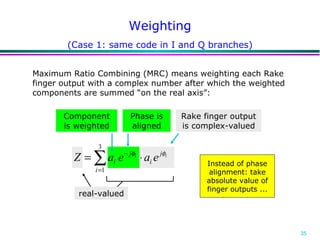
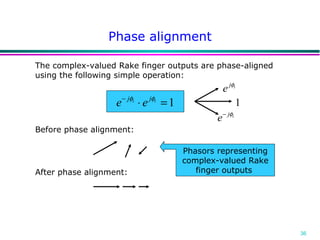


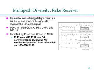


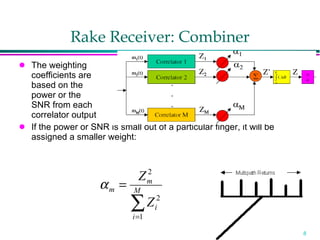


The document discusses the rake receiver, which is used to mitigate multipath fading effects in wireless communications. It operates by using multiple "fingers" to capture signal energy from different propagation paths. Each finger correlates the received signal with a reference signal and applies appropriate delays. The outputs of the fingers are then combined, such as by maximum ratio combining, to improve the overall signal quality by constructively adding the energy from different paths. The rake receiver allows energy from all propagation paths to be captured and combined, increasing the signal-to-noise ratio compared to a single propagation path.