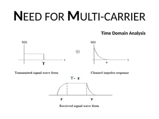
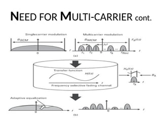
NEED FOR MULTI-CARRIERcont.
Pulse completely distorted. ISI
is significant in this case
.
Pulse extended but the extension are
much smaller than T the output
behaves like the transmitted
rectangular pulse
.
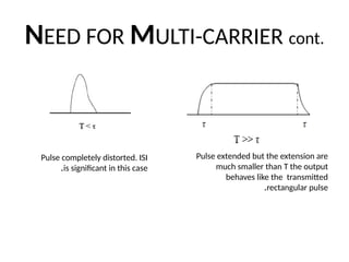
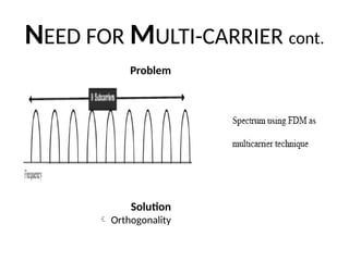
NEED FOR MULTI-CARRIERcont.
• Conclusion
Wide pulses is needed for simple equalization,
But
Narrow pulses is needed for high data rate
• Solution
Multiplexing
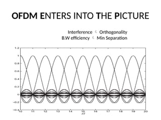
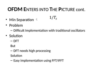
OFDM ENTERS INTOTHE PICTURE cont.
• Min Separation
• Problem
– Difficult Implementation with traditional oscillators
• Solution
– DFT
But
– DFT needs high processing
Solution
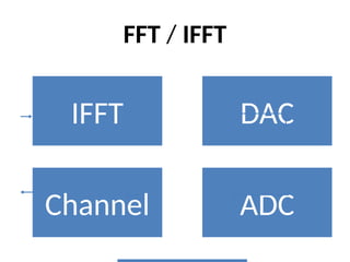
– Easy implementation using FFT/IFFT
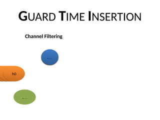
Cyclic prefix
• TheCP allows the receiver to absorb much more efficiently
the delay spread due to the multipath and to maintain
frequency Orthogonality.
• The CP that occupies a duration called the Guard Time (GT),
often denoted TG, is a temporal redundancy that must be
taken into account in data rate computations.
CHANNEL ESTIMATION cont.
Frequency(
sub
carriers)
Datasymbols
Pilot symbols
Time (OFDM Symbols) Time (OFDM Symbols)
Frequency(
sub
carriers)
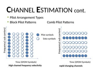
Pilot Arrangement Types
Block Pilot Patterns Comb Pilot Patterns
High channel frequency selectivity rapid changing channels
25.
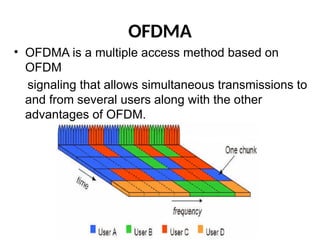
OFDMA
• OFDMA isa multiple access method based on
OFDM
signaling that allows simultaneous transmissions to
and from several users along with the other
advantages of OFDM.
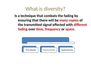
What is diversity?
Isa technique that combats the fading by
ensuring that there will be many copies of
the transmitted signal effected with different
fading over time, frequency or space.
Diversity types
Time diversity Frequency diversity Spatial diversity
29.
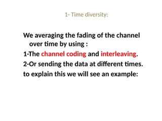
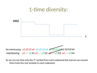
1- Time diversity:
Weaveraging the fading of the channel
over time by using :
1-The channel coding and interleaving.
2-Or sending the data at different times.
to explain this we will see an example:
30.
1-time diversity:
No interleavingx1 x2 x3 x4 y1 y2 y3 y4 z1 z2 z3 z4 h1 h2 h3 h4
interleaving x1 y1 z1 h1 x2 y2 z2 h2 x3 y3 z3 h3 x4 y4 z4 h4
So we can see that only the 3rd
symbol from each codeword lost and we can recover
them from the rest symbols in each codeword.
|
H(t)
|
t
31.
2- frequency diversity:
Thistype of diversity used for the frequency
selective channels as we will averaging the
fading over the frequency by using:
1-Multi-carrier technique like OFDM.
2-FHSS (frequency hope spread spectrum).
3-DSSS (direct sequence spread spectrum).
32.
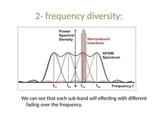
2- frequency diversity:
Wecan see that each sub-band will effecting with different
fading over the frequency.
33.
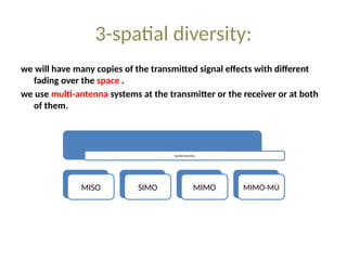
3-spatial diversity:
we willhave many copies of the transmitted signal effects with different
fading over the space .
we use multi-antenna systems at the transmitter or the receiver or at both
of them.
Spatial diversity
MISO SIMO MIMO MIMO-MU
34.
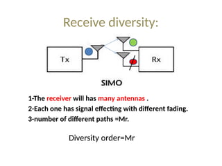
Receive diversity:
1-The receiverwill has many antennas .
2-Each one has signal effecting with different fading.
3-number of different paths =Mr.
Diversity order=Mr
35.
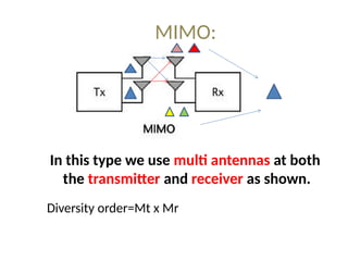
MIMO:
In this typewe use multi antennas at both
the transmitter and receiver as shown.
Diversity order=Mt x Mr
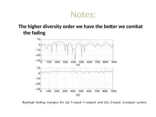
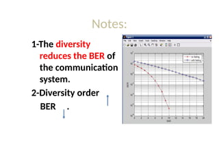
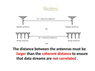
Notes:
The distance betweenthe antennas must be
larger than the coherent distance to ensure
that data streams are not correlated .
39.
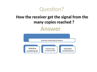
Question?
How the receiverget the signal from the
many copies reached ?
Answer
Diversity combining techniques
Selective
combining SC
Maximal ratio
combining MRC
Equal gain
combining EGC
40.
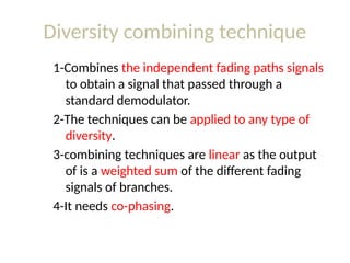
Diversity combining technique
1-Combinesthe independent fading paths signals
to obtain a signal that passed through a
standard demodulator.
2-The techniques can be applied to any type of
diversity.
3-combining techniques are linear as the output
of is a weighted sum of the different fading
signals of branches.
4-It needs co-phasing.
41.
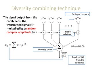
Diversity combining technique
Thesignal output from the
combiner is the
transmitted signal s(t)
multiplied by a random
complex amplitude term
Random SNR
from the
combiner
Fading of the path
Type of
technique
Diversity order
42.
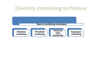
Diversity combining technique
Typesof combining techniques
Selection
combining
Threshold
combining
Maximal
ratio
combining
Equal gain
combining
43.
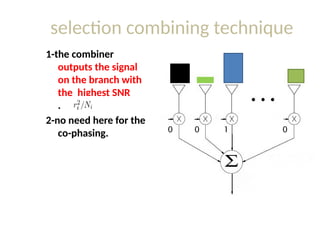
selection combining technique
1-thecombiner
outputs the signal
on the branch with
the highest SNR
.
2-no need here for the
co-phasing. 0 0 0
1
44.
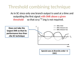
Threshold combining technique
Asin SC since only one branch output is used at a time and
outputting the first signal with SNR above a given
threshold so that co-phasing is not required.
Special case at diversity order =2
(SSC)
Does not take the
largest SNR so that its
performance less than
the SC technique
.
45.
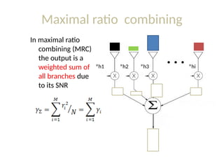
Maximal ratio combining
Inmaximal ratio
combining (MRC)
the output is a
weighted sum of
all branches due
to its SNR
h1
* h2
* h3
* hi
*
46.
Equal gain combiningtechnique
A simpler technique is equal-gain combining,
which co-phases the signals on each branch
and then combines them with equal weighting
47.
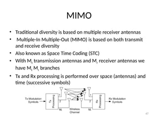
MIMO
• Traditional diversityis based on multiple receiver antennas
• Multiple-In Multiple-Out (MIMO) is based on both transmit
and receive diversity
• Also known as Space Time Coding (STC)
• With Mt transmission antennas and Mr receiver antennas we
have Mt Mr branches
• Tx and Rx processing is performed over space (antennas) and
time (successive symbols)
47
48.
MIMO or STC
•In Mobile communication systems it may be difficult to put
many antennas in the mobile unit
• Diversity in the downlink (from base station to mobile station)
can be achieved by Multiple-In Single-Out (MISO) (i.e., Mr=1)
• In the uplink (from mobile station to base station) diversity is
achieved my conventional diversity (SIMO)
• Hence, all diversity cost is moved to the base station
• All 3G and 4G mobile communication system employ MIMO in
their standard
48
49.
Type of MIMO
•Two major types of space time coding
– Space time block coding (STBC)
– Space time trellis coding (STTC)
• STBC is simpler by STTC can provide better
performance
• STBC is used in mobile communications. STTC
is not used in any systems yet
• We will talk only about STBC
49
50.
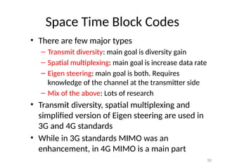
Space Time BlockCodes
• There are few major types
– Transmit diversity: main goal is diversity gain
– Spatial multiplexing: main goal is increase data rate
– Eigen steering: main goal is both. Requires
knowledge of the channel at the transmitter side
– Mix of the above: Lots of research
• Transmit diversity, spatial multiplexing and
simplified version of Eigen steering are used in
3G and 4G standards
• While in 3G standards MIMO was an
enhancement, in 4G MIMO is a main part
50
51.
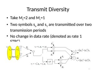
Transmit Diversity
• TakeMt=2 and Mr=1
• Two symbols so and s1 are transmitted over two
transmission periods
• No change in data rate (denoted as rate 1
STBC)
• Channel is known at receiver only
51
52.
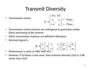
Transmit Diversity
• Transmissionmatrix:
• Transmission matrix columns are orthogonal to guarantee simple
linear processing at the receiver
• Other transmission matrices are defined in literature
• Received signal is:
• Performance is same as MRC with M=2
• However, if Tx Power is the same, then transmit diversity (2x1) is 3 dB
worse than (1x2)
52
1
* *
1
1 1 1
o
o o o
o
s s
r g n
R
s s
r g n
1
1
* *
1 1
o
Ant Ant
o o
o
s s Time
S
s s Time
53.
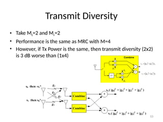
Transmit Diversity
• TakeMt=2 and Mr=2
• Performance is the same as MRC with M=4
• However, if Tx Power is the same, then transmit diversity (2x2)
is 3 dB worse than (1x4)
53
54.
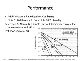
Performance
• MRRC=Maximal RatioReceiver Combining
• Note 3 dB difference in favor of Rx MRC diversity
Reference: S. Alamouti, a simple transmit diversity technique for
wireless communications,
IEEE JSAC, October 98
54
Order 2
Order
4
No diversity
55.
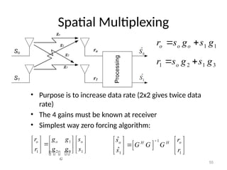
Spatial Multiplexing
• Purposeis to increase data rate (2x2 gives twice data
rate)
• The 4 gains must be known at receiver
• Simplest way zero forcing algorithm:
55
1 1
o o o
r s g s g
1 2 1 3
o
r s g s g
1
2 3
1 1
o
o o
G
g g
r s
g g
r s
1
1 1
ˆ
ˆ
o o
H H
s r
G G G
s r
56.
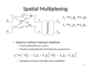
Spatial Multiplexing
• Optimummethod: Maximum Likelihood
– Try all combinations of s1 and s2
– Find the combination that minimizes the squared error:
– Complexity increases with high order modulation
56
2 2
2 2
1 1 1 1 2 1 3
ˆ ˆ ˆ ˆ
o o o o o
e e r s g s g r s g s g
1 1
o o o
r s g s g
1 2 1 3
o
r s g s g
57.
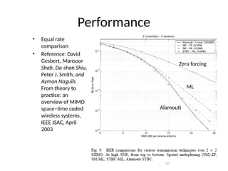
Performance
• Equal rate
comparison
•Reference: David
Gesbert, Mansoor
Shafi, Da-shan Shiu,
Peter J. Smith, and
Ayman Naguib,
From theory to
practice: an
overview of MIMO
space–time coded
wireless systems,
IEEE JSAC, April
2003
57
Zero forcing
ML
Alamouti
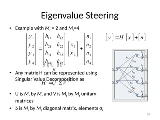
Eigenvalue Steering
• Examplewith Mt = 2 and Mr=4
• Any matrix H can be represented using
Singular Value Decomposition as
• U is Mr by Mr and V is Mt by Mt unitary
matrices
• is Mr by Mt diagonal matrix, elements σi
59
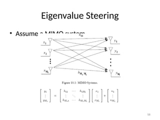
y H x n
1 11 12 1
2 21 22 1 2
3 31 32 2 3
4 41 42 4
H
y h h n
y h h x n
y h h x n
y h h n
H
H U V
60.
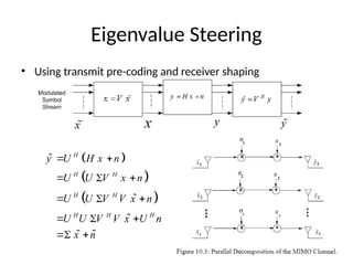
Eigenvalue Steering
• Usingtransmit pre-coding and receiver shaping
60
H
H H
H H
H H H
y U H x n
U U V x n
U U V V x n
U U V V x U n
x n
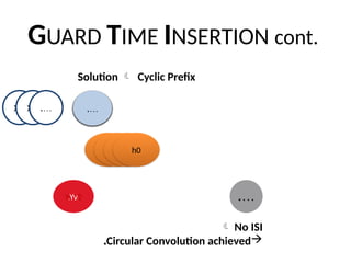
61.
Eigenvalue Steering
• Thisway we created r paths between the Tx and specific Rx
without any cross interference
• The channel (i.e., Channel State Information) must be known
to both transmitter and receiver
• The value of r = rank of matrix H, r min(Mt, Mr)
• Not all r paths have good SNR
• Data rate can increase by factor r
• See Appendix C for Singular Value Decomposition
• See Matlab function [U,S,V] = svd(X)
61
62.
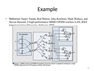
Example
• Reference: SanjivNanda, Rod Walton, John Ketchum, Mark Wallace, and
Steven Howard, A high-performance MIMO OFDM wireless LAN, IEEE
Communication Magazine, February 2005
62
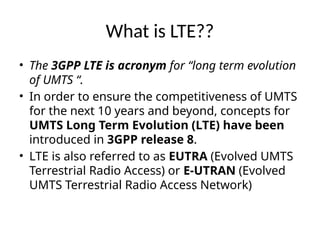
What is LTE??
•The 3GPP LTE is acronym for “long term evolution
of UMTS “.
• In order to ensure the competitiveness of UMTS
for the next 10 years and beyond, concepts for
UMTS Long Term Evolution (LTE) have been
introduced in 3GPP release 8.
• LTE is also referred to as EUTRA (Evolved UMTS
Terrestrial Radio Access) or E-UTRAN (Evolved
UMTS Terrestrial Radio Access Network)
65.
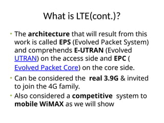
What is LTE(cont.)?
•The architecture that will result from this
work is called EPS (Evolved Packet System)
and comprehends E-UTRAN (Evolved
UTRAN) on the access side and EPC (
Evolved Packet Core) on the core side.
• Can be considered the real 3.9G & invited
to join the 4G family.
• Also considered a competitive system to
mobile WiMAX as we will show
(a) capabilities:-
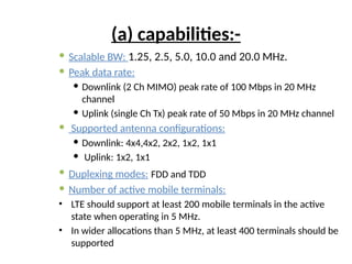
ScalableBW: 1.25, 2.5, 5.0, 10.0 and 20.0 MHz.
Peak data rate:
Downlink (2 Ch MIMO) peak rate of 100 Mbps in 20 MHz
channel
Uplink (single Ch Tx) peak rate of 50 Mbps in 20 MHz channel
Supported antenna configurations:
Downlink: 4x4,4x2, 2x2, 1x2, 1x1
Uplink: 1x2, 1x1
Duplexing modes: FDD and TDD
Number of active mobile terminals:
• LTE should support at least 200 mobile terminals in the active
state when operating in 5 MHz.
• In wider allocations than 5 MHz, at least 400 terminals should be
supported
69.
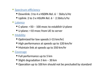
Spectrum efficiency
Downlink: 3 to 4 x HSDPA Rel. 65bits/s/Hz
Uplink: 2 to 3 x HSUPA Rel. 62.5bits/s/hz
Latency
C-plane: <50 – 100 msec to establish U-plane
U-plane: <10 msec from UE to server
Mobility
Optimized for low speeds (<15 km/hr)
High performance at speeds up to 120 km/hr
Maintain link at speeds up to 350 km/hr
Coverage
Full performance up to 5 km
Slight degradation 5 km – 30 km
Operation up to 100 km should not be precluded by standard
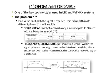
(1)OFDM and OFDMA:-
One of the key technologies used in LTE and WiMAX systems.
The problem ???
Due to the multipath the signal is received from many paths with
different phases that will result in
DELAY SPREAD :symbol received along a delayed path to “bleed”
into a subsequent symbol (ISI)
FREQUENCY SELECTIVE FADING: : some frequencies within the
signal passband undergo constructive interference while others
encounter destructive interference.The composite received signal
is distorted
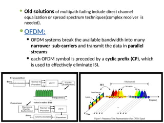
72.
Old solutionsof multipath fading include direct channel
equalization or spread spectrum techniques(complex receiver is
needed).
OFDM:
OFDM systems break the available bandwidth into many
narrower sub-carriers and transmit the data in parallel
streams
each OFDM symbol is preceded by a cyclic prefix (CP), which
is used to effectively eliminate ISI.
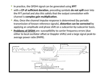
73.
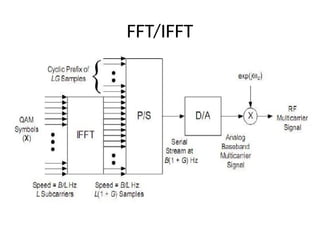
In practice,the OFDM signal can be generated using IFFT
with a CP of sufficient duration, preceding symbols do not spill over into
the FFT period and also this satisfy that the output convolution with
channel is complex gain multiplication.
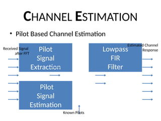
Also, Once the channel impulse response is determined (by periodic
transmission of known reference signals), distortion can be corrected by
applying an amplitude and phase shift on a subcarrier-by-subcarrier basis.
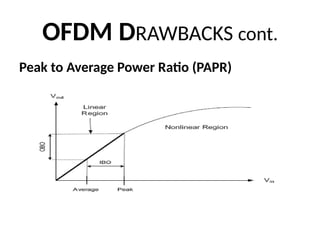
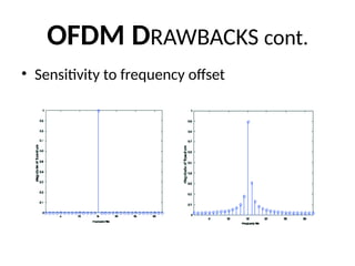
Problems of OFDM are: susceptibility to carrier frequency errors (due
either to local oscillator offset or Doppler shifts) and a large signal peak-to-
average power ratio (PAPR).
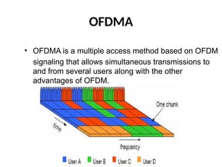
74.
OFDMA
• OFDMA isa multiple access method based on OFDM
signaling that allows simultaneous transmissions to
and from several users along with the other
advantages of OFDM.
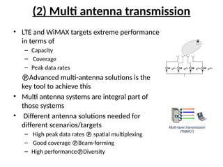
(2) Multi antennatransmission
• LTE and WiMAX targets extreme performance
in terms of
– Capacity
– Coverage
– Peak data rates
Advanced multi-antenna solutions is the
key tool to achieve this
• Multi antenna systems are integral part of
those systems
• Different antenna solutions needed for
different scenarios/targets
– High peak data rates spatial multiplexing
– Good coverage Beam-forming
– High performanceDiversity
77.
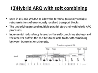
(3)Hybrid ARQ withsoft combining
• used in LTE and WiMAX to allow the terminal to rapidly request
retransmissions of erroneously received transport blocks.
• The underlying protocol multiple parallel stop-and-wait hybrid ARQ
processes
• Incremental redundancy is used as the soft combining strategy and
the receiver buffers the soft bits to be able to do soft combining
between transmission attempts.
78.
(1)Spectrum flexibility:
• Ahigh degree of spectrum flexibility is one of the
main characteristics of the LTE radio access.
• The aim of this spectrum flexibility is to allow for
the deployment of the LTE radio access in diverse
spectrum.
• The flexibility includes:
– Different duplex arrangements.
– Different frequency-bands-of-operation.
– Different sizes of the available spectrum.
79.
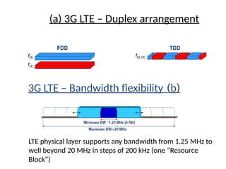
(a) 3G LTE– Duplex arrangement
(
b
)
3G LTE – Bandwidth flexibility
LTE physical layer supports any bandwidth from 1.25 MHz to
well beyond 20 MHz in steps of 200 kHz (one ”Resource
Block”)
80.
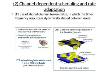
(2) Channel-dependent schedulingand rate
adaptation
• LTE use of shared-channel transmission, in which the time-
frequency resource is dynamically shared between users.
81.
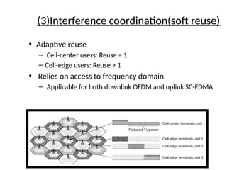
(3)Interference coordination(soft reuse)
•Adaptive reuse
– Cell-center users: Reuse = 1
– Cell-edge users: Reuse > 1
• Relies on access to frequency domain
– Applicable for both downlink OFDM and uplink SC-FDMA
82.
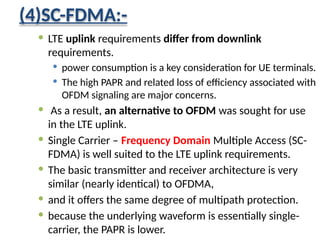
(4)SC-FDMA:-
LTE uplinkrequirements differ from downlink
requirements.
power consumption is a key consideration for UE terminals.
The high PAPR and related loss of efficiency associated with
OFDM signaling are major concerns.
As a result, an alternative to OFDM was sought for use
in the LTE uplink.
Single Carrier – Frequency Domain Multiple Access (SC-
FDMA) is well suited to the LTE uplink requirements.
The basic transmitter and receiver architecture is very
similar (nearly identical) to OFDMA,
and it offers the same degree of multipath protection.
because the underlying waveform is essentially single-
carrier, the PAPR is lower.
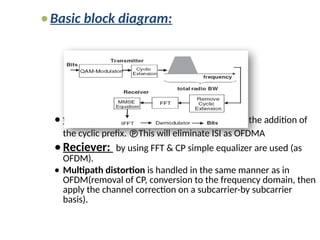
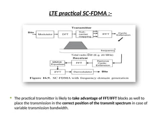
83.
Basic block diagram:
transmitter :a QAM modulator coupled with the addition of
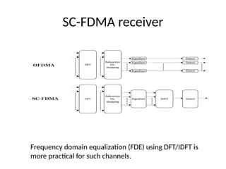
the cyclic prefix. This will eliminate ISI as OFDMA
Reciever: by using FFT & CP simple equalizer are used (as
OFDM).
Multipath distortion is handled in the same manner as in
OFDM(removal of CP, conversion to the frequency domain, then
apply the channel correction on a subcarrier-by subcarrier
basis).
84.
LTE practical SC-FDMA:-
The practical transmitter is likely to take advantage of FFT/IFFT blocks as well to
place the transmission in the correct position of the transmit spectrum in case of
variable transmission bandwidth.
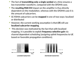
The factof transmitting only a single symbol at a time ensures a
low transmitter waveform, compared with the OFDMA case.
The resulting PAR/CM impact on the amplifier is thus directly
dependent on the modulation, whereas with the OFDMA case it is
the amount of subcarriers.
SC-FDMA subcarriers can be mapped in one of two ways: localized
or distributed
However, the current working assumption is that LTE will use
localized subcarrier mapping.
This decision was motivated by the fact that with localized
mapping, it is possible to exploit frequency selective gain via
channel dependent scheduling (assigning uplink frequencies to UE
based on favorable propagation conditions).
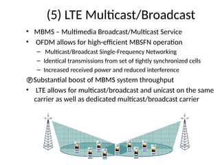
87.
(5) LTE Multicast/Broadcast
•MBMS – Multimedia Broadcast/Multicast Service
• OFDM allows for high-efficient MBSFN operation
– Multicast/Broadcast Single-Frequency Networking
– Identical transmissions from set of tightly synchronized cells
– Increased received power and reduced interference
Substantial boost of MBMS system throughput
• LTE allows for multicast/broadcast and unicast on the same
carrier as well as dedicated multicast/broadcast carrier
Introduction
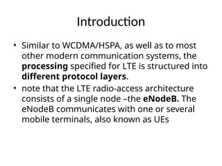
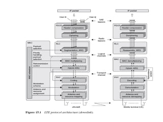
• Similar toWCDMA/HSPA, as well as to most
other modern communication systems, the
processing specified for LTE is structured into
different protocol layers.
• note that the LTE radio-access architecture
consists of a single node –the eNodeB. The
eNodeB communicates with one or several
mobile terminals, also known as UEs
91.
Packet Data ConvergenceProtocol (PDCP)
• performs IP header compression
• to reduce the number of bits to transmit
over the radio interface.
• The header compression mechanism is
based on Robust Header Compression
(ROHC)a standardized header-
compression algorithm also used in
WCDMA
• PDCP is also responsible for ciphering
and integrity protection of the
transmitted data. At the receiver side, the
PDCP protocol performs the
92.
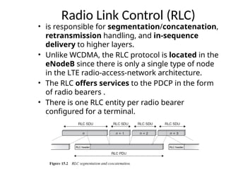
Radio Link Control(RLC)
• is responsible for segmentation/concatenation,
retransmission handling, and in-sequence
delivery to higher layers.
• Unlike WCDMA, the RLC protocol is located in the
eNodeB since there is only a single type of node
in the LTE radio-access-network architecture.
• The RLC offers services to the PDCP in the form
of radio bearers .
• There is one RLC entity per radio bearer
configured for a terminal.
93.
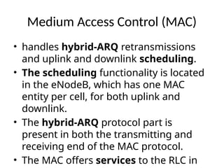
Medium Access Control(MAC)
• handles hybrid-ARQ retransmissions
and uplink and downlink scheduling.
• The scheduling functionality is located
in the eNodeB, which has one MAC
entity per cell, for both uplink and
downlink.
• The hybrid-ARQ protocol part is
present in both the transmitting and
receiving end of the MAC protocol.
• The MAC offers services to the RLC in
94.
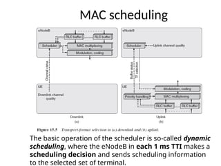
MAC scheduling
The basicoperation of the scheduler is so-called dynamic
scheduling, where the eNodeB in each 1 ms TTI makes a
scheduling decision and sends scheduling information
to the selected set of terminal.
95.
Downlink scheduling
• dynamicallycontrolling the
terminal(s) to transmit to
• the set of resource blocks
upon which the terminal’s
DL-SCH should be
transmitted.
• Transport-format
selection(selection of
transport-block size,
modulation scheme, and
antenna mapping)
• And logical-channel
multiplexing for downlink
transmissions
UL scheduling
• dynamically control which
mobile terminals are to
transmit on their UL-SCH
• and on which uplink
time/frequency resources
• uplink scheduling decision
is taken per mobile terminal
and not per radio bearer.
96.
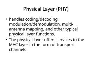
Physical Layer (PHY)
•handles coding/decoding,
modulation/demodulation, multi-
antenna mapping, and other typical
physical layer functions.
• The physical layer offers services to the
MAC layer in the form of transport
channels
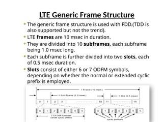
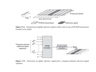
LTE Generic FrameStructure
The generic frame structure is used with FDD.(TDD is
also supported but not the trend).
LTE frames are 10 msec in duration.
They are divided into 10 subframes, each subframe
being 1.0 msec long.
Each subframe is further divided into two slots, each
of 0.5 msec duration.
Slots consist of either 6 or 7 ODFM symbols,
depending on whether the normal or extended cyclic
prefix is employed.
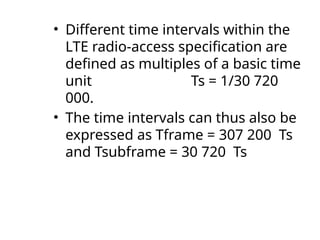
99.
• Different timeintervals within the
LTE radio-access specification are
defined as multiples of a basic time
unit Ts = 1/30 720
000.
• The time intervals can thus also be
expressed as Tframe = 307 200 Ts
and Tsubframe = 30 720 Ts
100.
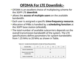
OFDMA For LTEDownlink:-
OFDMA is an excellent choice of multiplexing scheme for
the 3GPP LTE downlink
allows the access of multiple users on the available
bandwidth.
Each user is assigned a specific time-frequency resource.
Allocation of PRBs is handled by a scheduling function at
the 3GPP base station (eNodeB).
The total number of available subcarriers depends on the
overall transmission bandwidth of the system. The LTE
specifications define parameters for system bandwidths
from 1.25 MHz to 20 MHz as shown in Table.
101.
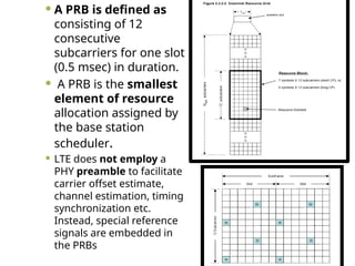
A PRBis defined as
consisting of 12
consecutive
subcarriers for one slot
(0.5 msec) in duration.
A PRB is the smallest
element of resource
allocation assigned by
the base station
scheduler.
LTE does not employ a
PHY preamble to facilitate
carrier offset estimate,
channel estimation, timing
synchronization etc.
Instead, special reference
signals are embedded in
the PRBs
102.
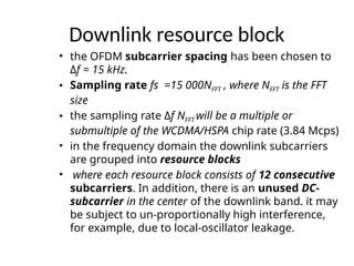
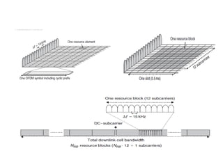
Downlink resource block
•the OFDM subcarrier spacing has been chosen to
Δf = 15 kHz.
• Sampling rate fs =15 000NFFT , where NFFT is the FFT
size
• the sampling rate Δf NFFT will be a multiple or
submultiple of the WCDMA/HSPA chip rate (3.84 Mcps)
• in the frequency domain the downlink subcarriers
are grouped into resource blocks
• where each resource block consists of 12 consecutive
subcarriers. In addition, there is an unused DC-
subcarrier in the center of the downlink band. it may
be subject to un-proportionally high interference,
for example, due to local-oscillator leakage.
104.
Downlink reference signal
•To carry out coherent demodulation of
different downlink physical channels,
• a mobile terminal needs estimates of
the downlink channel
– Cell-specific downlink reference signals.
– UE-specific reference signal.
– MBSFN reference signals
105.
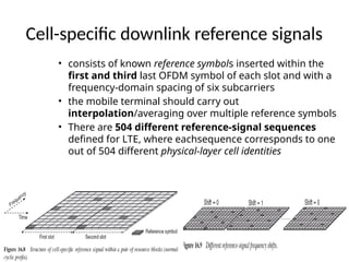
Cell-specific downlink referencesignals
• consists of known reference symbols inserted within the
first and third last OFDM symbol of each slot and with a
frequency-domain spacing of six subcarriers
• the mobile terminal should carry out
interpolation/averaging over multiple reference symbols
• There are 504 different reference-signal sequences
defined for LTE, where eachsequence corresponds to one
out of 504 different physical-layer cell identities
106.
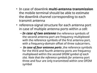
• In caseof downlink multi-antenna transmission
the mobile terminal should be able to estimate
the downlink channel corresponding to each
transmit antenna
• reference-signal structure for each antenna port
in case of multiple antenna ports within a cell:
– In case of two antenna the reference symbols of
the second antenna port are frequency multiplexed
with the reference symbols of the first antenna port,
with a frequency-domain offset of three subcarriers.
– In case of four antenna ports ,the reference symbols
for the third and fourth antenna ports are frequency
multiplexed within the second OFDM symbol of each
slot. Note that the reference symbols for antenna port
three and four are only transmitted within one OFDM
symbol
108.
UE-specific reference signals
•LTE also allows for more general beam-
forming. In order to allow for channel
estimation also for such transmissions,
additional reference signals are needed.
• As such a reference signal can only be
used by the specific terminal to which
the beam-formed transmission is
intended, it is referred to as a UE-specific
reference signal .
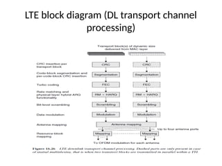
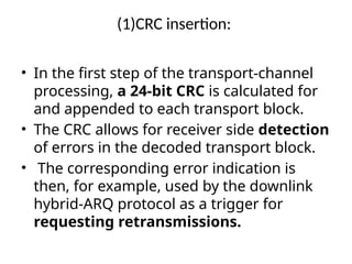
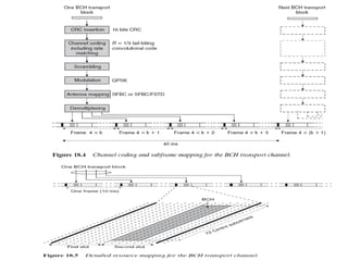
(1)CRC insertion:
• Inthe first step of the transport-channel
processing, a 24-bit CRC is calculated for
and appended to each transport block.
• The CRC allows for receiver side detection
of errors in the decoded transport block.
• The corresponding error indication is
then, for example, used by the downlink
hybrid-ARQ protocol as a trigger for
requesting retransmissions.
111.
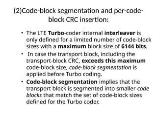
(2)Code-block segmentation andper-code-
block CRC insertion:
• The LTE Turbo-coder internal interleaver is
only defined for a limited number of code-block
sizes with a maximum block size of 6144 bits.
• In case the transport block, including the
transport-block CRC, exceeds this maximum
code-block size, code-block segmentation is
applied before Turbo coding.
• Code-block segmentation implies that the
transport block is segmented into smaller code
blocks that match the set of code-block sizes
defined for the Turbo coder.
112.
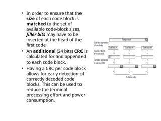
• In orderto ensure that the
size of each code block is
matched to the set of
available code-block sizes,
filler bits may have to be
inserted at the head of the
first code
• An additional (24 bits) CRC is
calculated for and appended
to each code block.
• Having a CRC per code block
allows for early detection of
correctly decoded code
blocks. This can be used to
reduce the terminal
processing effort and power
consumption.
113.
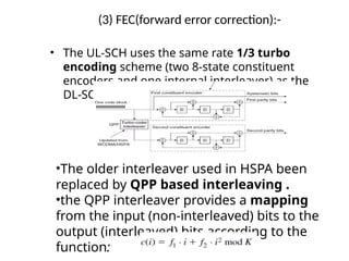
(3) FEC(forward errorcorrection):-
• The UL-SCH uses the same rate 1/3 turbo
encoding scheme (two 8-state constituent
encoders and one internal interleaver) as the
DL-SCH.
•The older interleaver used in HSPA been
replaced by QPP based interleaving .
•the QPP interleaver provides a mapping
from the input (non-interleaved) bits to the
output (interleaved) bits according to the
function:
114.
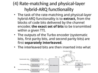
(4) Rate-matching andphysical-layer
hybrid-ARQ functionality
• The task of the rate-matching and physical-layer
hybrid-ARQ functionality is to extract, from the
blocks of code bits delivered by the channel
encoder, the exact set of bits to be transmitted
within a given TTI.
• The outputs of the Turbo encoder (systematic
bits, first parity bits, and second parity bits) are
first separately interleaved.
• The interleaved bits are then inserted into what
can be described as a circular buffer with the
systematic bits inserted first, followed by
alternating insertion of the first and second
parity bits.
• The bit selection then extracts consecutive bits
from the circular buffer
115.
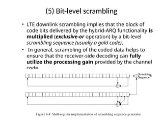
(5) Bit-level scrambling
•LTE downlink scrambling implies that the block of
code bits delivered by the hybrid-ARQ functionality is
multiplied (exclusive-or operation) by a bit-level
scrambling sequence (usually a gold code).
• In general, scrambling of the coded data helps to
ensure that the receiver-side decoding can fully
utilize the processing gain provided by the channel
code
116.
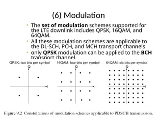
(6) Modulation
• Theset of modulation schemes supported for
the LTE downlink includes QPSK, 16QAM, and
64QAM.
• All these modulation schemes are applicable to
the DL-SCH, PCH, and MCH transport channels.
• only QPSK modulation can be applied to the BCH
transport channel.
117.
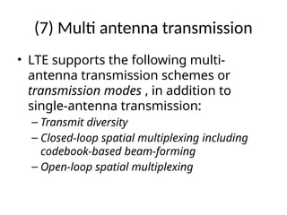
(7) Multi antennatransmission
• LTE supports the following multi-
antenna transmission schemes or
transmission modes , in addition to
single-antenna transmission:
– Transmit diversity
– Closed-loop spatial multiplexing including
codebook-based beam-forming
– Open-loop spatial multiplexing
118.
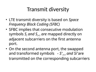
Transmit diversity
• LTEtransmit diversity is based on Space
Frequency Block Coding (SFBC)
• SFBC implies that consecutive modulation
symbols Si and Si+1 are mapped directly on
adjacent subcarriers on the first antenna
port.
• On the second antenna port, the swapped
and transformed symbols - S*
i+1 and Si*
are
transmitted on the corresponding subcarriers
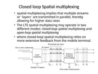
Closed loop Spatialmultiplexing
• spatial multiplexing implies that multiple streams
or ‘ layers ’ are transmitted in parallel, thereby
allowing for higher data rates
• The LTE spatial multiplexing may operate in two
different modes: closed-loop spatial multiplexing and
open-loop spatial multiplexing
• where closed-loop spatial multiplexing relies on
more extensive feedback from the mobile terminal.
122.
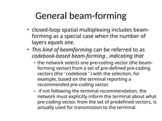
General beam-forming
• closed-loopspatial multiplexing includes beam-
forming as a special case when the number of
layers equals one.
• This kind of beamforming can be referred to as
codebook-based beam-forming , indicating that
– the network selects one pre-coding vector (the beam-
forming vector) from a set of pre-defined pre-coding
vectors (the ‘ codebook ’ ) with the selection, for
example, based on the terminal reporting a
recommended pre-coding vector.
– if not following the terminal recommendation, the
network must explicitly inform the terminal about what
pre-coding vector, from the set of predefined vectors, is
actually used for transmission to the terminal.
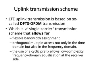
Uplink transmission scheme
•LTE uplink transmission is based on so-
called DFTS-OFDM transmission
• Which is a‘ single-carrier ’ transmission
scheme that allows for
– flexible bandwidth assignment
– orthogonal multiple access not only in the time
domain but also in the frequency domain.
– the use of a cyclic prefix allows low-complexity
frequency-domain equalization at the receiver
side.
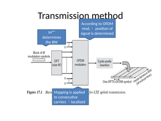
DFT implementation
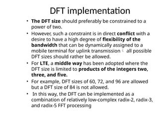
• TheDFT size should preferably be constrained to a
power of two.
• However, such a constraint is in direct conflict with a
desire to have a high degree of flexibility of the
bandwidth that can be dynamically assigned to a
mobile terminal for uplink transmission all possible
DFT sizes should rather be allowed.
• For LTE, a middle way has been adopted where the
DFT size is limited to products of the integers two,
three, and five.
• For example, DFT sizes of 60, 72, and 96 are allowed
but a DFT size of 84 is not allowed.
• In this way, the DFT can be implemented as a
combination of relatively low-complex radix-2, radix-3,
and radix-5 FFT processing
127.
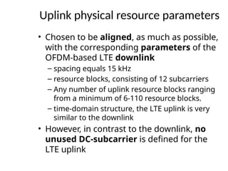
Uplink physical resourceparameters
• Chosen to be aligned, as much as possible,
with the corresponding parameters of the
OFDM-based LTE downlink
– spacing equals 15 kHz
– resource blocks, consisting of 12 subcarriers
– Any number of uplink resource blocks ranging
from a minimum of 6-110 resource blocks.
– time-domain structure, the LTE uplink is very
similar to the downlink
• However, in contrast to the downlink, no
unused DC-subcarrier is defined for the
LTE uplink
128.
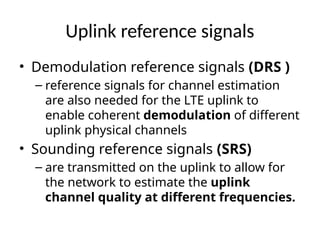
Uplink reference signals
•Demodulation reference signals (DRS )
– reference signals for channel estimation
are also needed for the LTE uplink to
enable coherent demodulation of different
uplink physical channels
• Sounding reference signals (SRS)
– are transmitted on the uplink to allow for
the network to estimate the uplink
channel quality at different frequencies.
129.
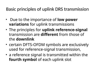
Basic principles ofuplink DRS transmission
• Due to the importance of low power
variations for uplink transmissions
• The principles for uplink reference-signal
transmission are different from those of
the downlink
• certain DFTS-OFDM symbols are exclusively
used for reference-signal transmission,
• a reference signal is transmitted within the
fourth symbol of each uplink slot
131.
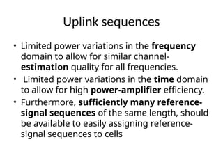
Uplink sequences
• Limitedpower variations in the frequency
domain to allow for similar channel-
estimation quality for all frequencies.
• Limited power variations in the time domain
to allow for high power-amplifier efficiency.
• Furthermore, sufficiently many reference-
signal sequences of the same length, should
be available to easily assigning reference-
signal sequences to cells
132.
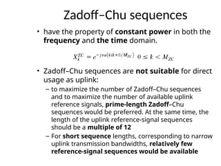
Zadoff–Chu sequences
• havethe property of constant power in both the
frequency and the time domain.
• Zadoff–Chu sequences are not suitable for direct
usage as uplink:
– to maximize the number of Zadoff–Chu sequences
and to maximize the number of available uplink
reference signals, prime-length Zadoff–Chu
sequences would be preferred. At the same time, the
length of the uplink reference-signal sequences
should be a multiple of 12
– For short sequence lengths, corresponding to narrow
uplink transmission bandwidths, relatively few
reference-signal sequences would be available
133.
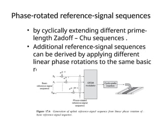
Phase-rotated reference-signal sequences
•by cyclically extending different prime-
length Zadoff – Chu sequences .
• Additional reference-signal sequences
can be derived by applying different
linear phase rotations to the same basic
reference-signal sequences
134.
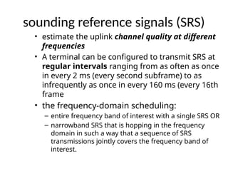
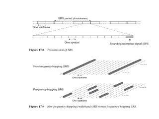
sounding reference signals(SRS)
• estimate the uplink channel quality at different
frequencies
• A terminal can be configured to transmit SRS at
regular intervals ranging from as often as once
in every 2 ms (every second subframe) to as
infrequently as once in every 160 ms (every 16th
frame
• the frequency-domain scheduling:
– entire frequency band of interest with a single SRS OR
– narrowband SRS that is hopping in the frequency
domain in such a way that a sequence of SRS
transmissions jointly covers the frequency band of
interest.
136.
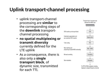
Uplink transport-channel processing
•uplink transport-channel
processing are similar to
the corresponding steps of
the downlink transport-
channel processing
• no spatial multiplexing or
transmit diversity
currently defined for the
LTE uplink
• As a consequence, there is
also only a single
transport block, of
dynamic size, transmitted
for each TTI.
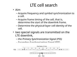
LTE cell search
•Aim
– Acquire frequency and symbol synchronization to
a cell.
– Acquire frame timing of the cell, that is,
determine the start of the downlink frame.
– Determine the physical-layer cell identity of the
cell.
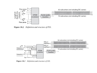
• two special signals are transmitted on the
LTE downlink,
– the Primary Synchronization Signal (PSS)
– Secondary Synchronization Signal (SSS)
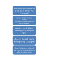
140.
a terminal synchronizesto
a cell. Once it knew PSS
5ms delay
acquires the physical-layer
identity
(but not the identity group) of
the cell using PSS .
Acquires physical layer
identity group using SSS
signal
detects the cell frame
timing using SSS signal
Once this has been achieved,
the terminal has to acquire the
cell system information
141.
System information
• InLTE, system information is delivered by
two different mechanisms relying on two
different transport channels
– A limited amount of system information,
corresponding to the so-called Master Information
Block (MIB), is transmitted using the BCH.
– The main part of the system information,
corresponding to different so-called System
Information Blocks (SIBs), is transmitted using the
downlink shared channel (DL-SCH).
143.
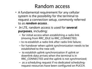
Random access
• Afundamental requirement for any cellular
system is the possibility for the terminal to
request a connection setup, commonly referred
to as random access .
• In LTE, random access is used for several
purposes, including:
– for initial access when establishing a radio link
(moving from RRC_IDLE to RRC_CONNECTED;
– to re-establish a radio link after radio link failure;
– for handover when uplink synchronization needs to be
established to the new cell;
– to establish uplink synchronization if uplink or
downlink data arrives when the terminal is in
RRC_CONNECTED and the uplink is not synchronized;
– as a scheduling request if no dedicated scheduling-
request resources have been configured on PUCCH.
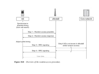
145.
The first stepconsists of transmission of a random-
access preamble, allowing the eNodeB to estimate
the transmission timing of the terminal. Uplink
synchronization is necessary as the terminal
otherwise cannot transmit any uplink data.
The second step consists of the network transmitting a
timing advance command to adjust the terminal transmit
timing, based on the timing estimate in the first step. In
addition to establishing uplink synchronization, the second
step also assigns uplink resources to the terminal to be
used in the third step in the random-access procedure.
The third step consists of transmission of the mobile-
terminal identity to the network using the UL-SCH
similar to normal scheduled data. The exact content of
this signaling depends on the state of the terminal, in
particular whether it is previously known to the
network or not.
The fourth and final step consists of transmission of a
contention-resolution message from the network to
the terminal on the DL-SCH. This step also resolves any
contention due to multiple terminals trying to access
the system using the same random-access resource.
146.
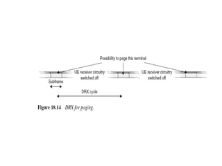
paging
• Paging isused for network-initiated
connection setup.
• An efficient paging procedure should allow
the terminal to sleep with no receiver
processing most of the time and to briefly
wake up at predefined time intervals to
monitor paging information from the
network.
• In LTE, no separate paging-indicator channel
is used
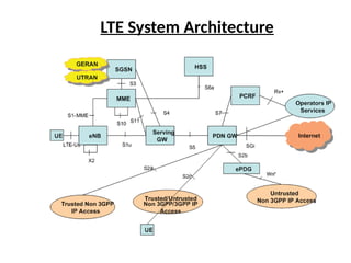
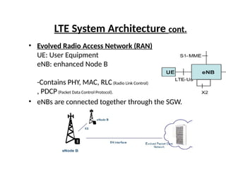
LTE System Architecturecont.
• Evolved Radio Access Network (RAN)
UE: User Equipment
eNB: enhanced Node B
-Contains PHY, MAC, RLC(Radio Link Control)
, PDCP(Packet Data Control Protocol).
• eNBs are connected together through the SGW.
151.
LTE System Architecturecont.
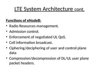
Functions of eNodeB:
• Radio Resources management.
• Admission control.
• Enforcement of negotiated UL QoS.
• Cell information broadcast.
• Ciphering/deciphering of user and control plane
data
• Compression/decompression of DL/UL user plane
packet headers.
152.
LTE System Architecturecont.
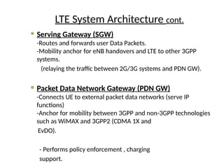
Serving Gateway (SGW)
-Routes and forwards user Data Packets.
-Mobility anchor for eNB handovers and LTE to other 3GPP
systems.
(relaying the traffic between 2G/3G systems and PDN GW).
Packet Data Network Gateway (PDN GW)
-Connects UE to external packet data networks (serve IP
functions)
-Anchor for mobility between 3GPP and non-3GPP technologies
such as WiMAX and 3GPP2 (CDMA 1X and
EvDO).
- Performs policy enforcement , charging
support.
153.
LTE System Architecturecont.
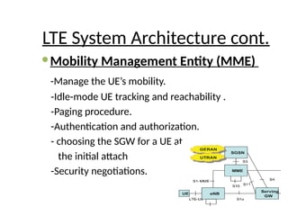
Mobility Management Entity (MME)
-Manage the UE’s mobility.
-Idle-mode UE tracking and reachability .
-Paging procedure.
-Authentication and authorization.
- choosing the SGW for a UE at
the initial attach
-Security negotiations.
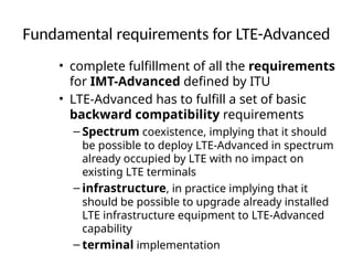
Fundamental requirements forLTE-Advanced
• complete fulfillment of all the requirements
for IMT-Advanced defined by ITU
• LTE-Advanced has to fulfill a set of basic
backward compatibility requirements
– Spectrum coexistence, implying that it should
be possible to deploy LTE-Advanced in spectrum
already occupied by LTE with no impact on
existing LTE terminals
– infrastructure, in practice implying that it
should be possible to upgrade already installed
LTE infrastructure equipment to LTE-Advanced
capability
– terminal implementation
156.
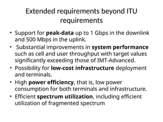
Extended requirements beyondITU
requirements
• Support for peak-data up to 1 Gbps in the downlink
and 500 Mbps in the uplink.
• Substantial improvements in system performance
such as cell and user throughput with target values
significantly exceeding those of IMT-Advanced.
• Possibility for low-cost infrastructure deployment
and terminals.
• High power efficiency, that is, low power
consumption for both terminals and infrastructure.
• Efficient spectrum utilization, including efficient
utilization of fragmented spectrum
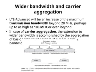
Wider bandwidth andcarrier
aggregation
• LTE-Advanced will be an increase of the maximum
transmission bandwidth beyond 20 MHz, perhaps
up to as high as 100 MHz or even beyond
• In case of carrier aggregation, the extension to
wider bandwidth is accomplished by the aggregation
of basic component carriers of a more narrow
bandwidth
159.
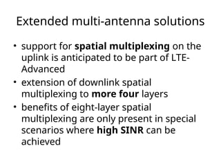
Extended multi-antenna solutions
•support for spatial multiplexing on the
uplink is anticipated to be part of LTE-
Advanced
• extension of downlink spatial
multiplexing to more four layers
• benefits of eight-layer spatial
multiplexing are only present in special
scenarios where high SINR can be
achieved
160.
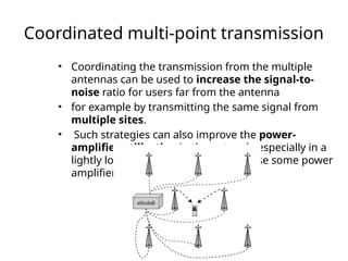
Coordinated multi-point transmission
•Coordinating the transmission from the multiple
antennas can be used to increase the signal-to-
noise ratio for users far from the antenna
• for example by transmitting the same signal from
multiple sites.
• Such strategies can also improve the power-
amplifier utilization in the network, especially in a
lightly loaded network where otherwise some power
amplifiers would be idle
161.
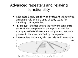
Advanced repeaters andrelaying
functionality
• Repeaters simply amplify and forward the received
analog signals and are used already today for
handling coverage holes.
• “L1 relays”schemes where the network can control
the transmission power of the repeater and, for
example, activate the repeater only when users are
present in the area handled by the repeater
• intermediate node may also decode and re-encode
any received data prior to forwarding it to the served
users. This is often referred to as decode-and-
forward relaying
162.
The proposals couldroughly be
categorized into:
• Various concepts for Relay Nodes
• UE Dual TX antenna solutions for SU-MIMO and
diversity MIMO
• Scalable system bandwidth exceeding 20 MHz,
Potentially up to 100MHz
• Local area optimization of air interface
• Nomadic / Local Area network and mobility solutions
• Flexible Spectrum Usage
• Cognitive Radio
• Automatic and autonomous network configuration
and operation
• Enhanced precoding and forward error correction
• Interference management and suppression
• Asymmetric bandwidth assignment for FDD
• Hybrid OFDMA and SC-FDMA in uplink
163.
Timeframe
• Standardization isexpected to be
included in 3GPP Release 10 timeframe.
• The importance and timeframe of LTE
Advanced will of course largely depend
on the success of LTE itself.
• If possible LTE-Advanced will be a
software upgrade for LTE networks.
164.
Technology Demonstrations
• InFebruary 2007 NTT DoCoMo
announced the completion of a 4G trial
• where they achieved a maximum packet
transmission rate of approximately 5
Gbit/s in the downlink using 100MHz
frequency bandwidth to a mobile
station moving at 10 km/h
Editor's Notes
#19 Circular Convolution multiplication in freq domain
#24 Block Pilot Patterns High channel frequency selectivity Estimation at all subcarriers
Comb Pilot Patternsrapid changing channels Estimation at all time due to fast variations
interpolation


![Eigenvalue Steering
• This way we created r paths between the Tx and specific Rx
without any cross interference
• The channel (i.e., Channel State Information) must be known
to both transmitter and receiver
• The value of r = rank of matrix H, r min(Mt, Mr)
• Not all r paths have good SNR
• Data rate can increase by factor r
• See Appendix C for Singular Value Decomposition
• See Matlab function [U,S,V] = svd(X)
61](https://image.slidesharecdn.com/131959233-lte-pptx-250720180910-34fdf160/85/3GPP-lte-pptx-training-a-beginers-guide-pptx-61-320.jpg)


![[Year 2012-13] Mimo technology](https://cdn.slidesharecdn.com/ss_thumbnails/mimotechnology-180701101303-thumbnail.jpg?width=640&height=640&fit=bounds)