Downloaded 118 times


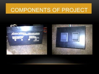
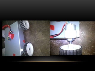


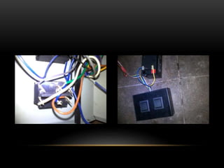


The document outlines a step-by-step guide to assemble a wired remote-controlled car, detailing required components and assembly procedures. Key steps include soldering wires to motors, attaching wheels, and connecting DPDT switches for direction control. The final instructions ensure functionality and proper wiring, enabling the car to move forward, backward, and turn as intended.


![Smart accident detector and intimator [autosaved]](https://cdn.slidesharecdn.com/ss_thumbnails/smartaccidentdetectorandintimatorautosaved-180331150920-thumbnail.jpg?width=640&height=640&fit=bounds)


