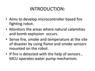
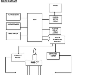
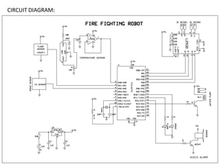
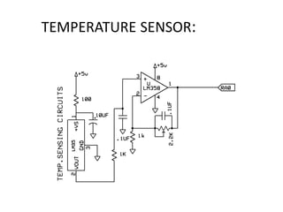
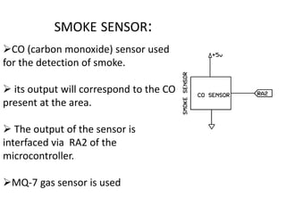
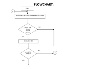
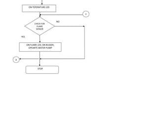
AUTOMATIC FIRE FIGHTING
ROBOT
Presented by:
DELIA JAMES
ANUSHA WILSON
INTRODUCTION:
• Aims to develop microcontroller based fire
fighting robot.
• Monitors the areas where natural calamities
and bomb explosion occurs.
• Sense fire, smoke and temperature at the site
of disaster by using flame and smoke sensors
mounted on the robot.
• If fire is detected with the help of sensors ,
MCU operates water pump mechanism.
OBJECTIVE:
• To detect fire in the disaster prone area.
• Also provides audio and visual indications.
• Extinguishes fire on detection.
• Reduces the efforts of human labour and
level of destruction.
MCU
MOTOR
INTERFACING
CIRCUITS
GEARED DC
MOTOR
GEARED DC
MOTOR
ROBOT
AUDIO &
VISUAL
ALARM
PUMP
FLAME SENSOR
SMOKE SENSOR
RELAY &
DRIVER
CIRCUIT
TEMP.SENSOR
BLOCK DIAGRAM
COMPONENTS :
•Flame sensor
•Smoke & Temperature sensor
•PIC 16F73
• Motor Driver & Geared DC Motor
•Relay
•Buzzer
•Led
•Pump
TEMPERATURE SENSOR:
 Transducers used for the measurement of
temperature at the site of disaster.
 Gives out electrical output to the existing
temperature.
 Output voltage is proportional to the Celsius
temperature.
SMOKE SENSOR:
 Smoke is a colloid and comprises a collection
of airborne solid and liquid particulates and
gases emitted when a material undergoes
combustion.
 It is commonly an unwanted by-product of
fires.
 The smoke sensor detects smoke and
provides output to the MCU.
FLAME SENSOR:
• A flame detector is a sensor designed to
detect and respond to the presence of a flame
or fire.
MICROCONTROLLER- PIC16F73:
 Takes or read data from the sensors and
controls all the functions of the whole system
by manipulating these data.
 Control the movement of robot.
 If the sensor outputs are found higher than
preset value it indicates presence of fire and
MCU operates the water pump mechanism.
MOTOR DRIVER:
 Provides an interface between the 5V logic
signal from the microcontroller & the high
current / high voltage power side to drive the
motor.
 Motor is an electromechanical device, which
convert electrical energy to rotation/
mechanical energy.
 DC Geared Motor is used to drive the robotic
vehicle.
VISUAL INDICATION & AUDIO ALARM:
 Visual indicators are used here for indicating
the conditions of the sensors, different
colored LEDs are used here.
 If any of the sensor output will be high, MCU
will turns ON the audio alarm for intimating
the condition to others.
RELAY & DRIVER CIRCUIT:
 Interfacing is required for connecting a relay
with any microcontroller.
 Relays are inductive loads and control water
pumps.
 Driving circuit is fixed between relays and
processor pins.
 The output of the microcontroller is fed to the
relay driver for current boosting. The output
of this magnetizes the relay.
WATER PUMP:
 Used to pump water when an abnormal
condition arises in the system.
 When excess temperature, smoke and flame
detected, the water pump starts pumping
water.
 Water pump is connected to the relay, the
relay becomes energizes according to the
instruction from the MCU.
WORKING:
• Consists of temperature sensor, smoke sensor, flame
sensor, MCU, water pump and geared motor.
• The robot continously monitors variation of the
surrounding area using these sensors.
• Robotic vehicle moves through the disaster area as per
the instructions from MCU.
• Whenever the temperature exceed a limit value and
flame and smoke detected MCU identifies that there is
presence of fire and operate water pump.
• MCU operates the relay through the relay interface.
• Audio and visual indications are attached to the robotic
system.
CIRCUIT DIAGRAM:
PIC16F73:
Control unit of this
project
28 pin package
3 Input/Output port- A,B
& C
5 Analog/Digital input
channels
Operating Frequency:
20Mhz
Clock Frequency:4Mhz
TEMPERATURE SENSOR:
FEATURES:
Sense the body temperature.
 Supply is connected to the source through a
current limiting resistor (100 ohm).
3rd pin of LM35 is grounded.
Output of sensor is in milli volt range and is
amplified using LM358 before feeding to the
MCU.
 The output from this circuit is fed to RA0 of the
MCU for further procedures.
SMOKE SENSOR:
CO (carbon monoxide) sensor used
for the detection of smoke.
 its output will correspond to the CO
present at the area.
 The output of the sensor is
interfaced via RA2 of the
microcontroller.
MQ-7 gas sensor is used
FLAME SENSOR:
•Flame sensor can detect flame or fire at
wavelength 750 nm
•Detect flame from distance of 20cm
•Detection angle 60
•Adjustable sensitivity
•Operating voltage :3.3-5V
•The sensor is kept at a certain distance away
from fire to avoid damage
WHEEL MOTOR DRIVER CIRCUIT (L293D)
•Interfacing unit
between MCU and DC
motor
•Controls two DC motors
MOTOR DRIVER
• Provides interfacing between MCU and wheel
motor
• Quadruple high current half H drivers
• Designed to provide bidirectional current up to
1A
• Wide supply voltage :4.5-36V
MOTOR CONTROL RELAY CIRCUIT
•Electrical relays are
interfaced to MCU via the
driving circuits
•Relay is used control the
water pump
AUDIO INDICATOR
•Buzzer is interfaced to
the MCU via the
transistor acting as a
switch
•MCU send high signal
to BC547
VISUAL INDICATORS:
•LED is used for the purpose of
visual indication. 3 LEDs are
interfaced indicating different
sensors
•They are interfaced to RC1,RC2
& RC3 of microcontroller.
•1K current limiting resistors are
used to interface the LEDs to the
microcontroller.
POWER SUPPLY
•Consist of 12V car
battery,voltage regulator IC
7805 and capacitor as filters
•Provides regulation of either
a fixed positive voltage,a
fixed negative voltage or an
adjustably set voltage
START
INITIALISATION OF PORTS, MEMORY LOCATIONS
X
CHECK FOR
SMOKE
SENSOR
OUTPUT
YES
NO
CHECK FOR
TEMP>40
YES
NO
ON SMOKE LED
FLOWCHART:
Y
X
ON FLAME LED, ON BUSSER,
OPEARTE WATER PUMP
NO
STOP
CHECK FOR
FLAME
SENSOR
ON TEPERATURE LED
Y
YES
ADVANTAGES
The fire detecting robot helps in following ways:
•To detect the exact direction of the fire source.
•Capability of sensing accurately with increased flexibility.
•Reduce human effort.
•Reliable and economical.
•Not sensitive to weather conditions.
DISADVANTAGES
• No monitoring system for the vehicle.
• No remote control for the robotic movement.
• Our system used only for less than 3.5Kg
application.
• It is not used to put out large fires.
APPLICATION:
• Can be used in server rooms.
• Extinguishes fire where probability of
explosion is high.
• Usable in Power plant control rooms, Captain
bridges,Flight control centres.
• Disaster area monitoring and rescue.
FUTURE SCOPE:
• Remote control of robot.
• Camera and Video transmission can be
added.
• Improve weight capacity of the robot.
CONCLUSION:
• Here we successfully developed the FIRE
EXTINGUSHER Robot.
• Robot detects temperature, smoke and flame at the
site where the robot exists.
• The movement of this robot vehicle is controlled by
MCU as per the program.
• This robot is help full in those areas where natural
calamity and bomb explosions where occurred.
• If fire is detected with the help of sensors, MCU
operates the water pump mechanism through relay
circuit.
THANK YOU

Fire fighting robot ppt

  • 1.
    AUTOMATIC FIRE FIGHTING ROBOT Presentedby: DELIA JAMES ANUSHA WILSON
  • 2.
    INTRODUCTION: • Aims todevelop microcontroller based fire fighting robot. • Monitors the areas where natural calamities and bomb explosion occurs. • Sense fire, smoke and temperature at the site of disaster by using flame and smoke sensors mounted on the robot. • If fire is detected with the help of sensors , MCU operates water pump mechanism.
  • 3.
    OBJECTIVE: • To detectfire in the disaster prone area. • Also provides audio and visual indications. • Extinguishes fire on detection. • Reduces the efforts of human labour and level of destruction.
  • 4.
    MCU MOTOR INTERFACING CIRCUITS GEARED DC MOTOR GEARED DC MOTOR ROBOT AUDIO& VISUAL ALARM PUMP FLAME SENSOR SMOKE SENSOR RELAY & DRIVER CIRCUIT TEMP.SENSOR BLOCK DIAGRAM
  • 5.
    COMPONENTS : •Flame sensor •Smoke& Temperature sensor •PIC 16F73 • Motor Driver & Geared DC Motor •Relay •Buzzer •Led •Pump
  • 6.
    TEMPERATURE SENSOR:  Transducersused for the measurement of temperature at the site of disaster.  Gives out electrical output to the existing temperature.  Output voltage is proportional to the Celsius temperature.
  • 7.
    SMOKE SENSOR:  Smokeis a colloid and comprises a collection of airborne solid and liquid particulates and gases emitted when a material undergoes combustion.  It is commonly an unwanted by-product of fires.  The smoke sensor detects smoke and provides output to the MCU.
  • 8.
    FLAME SENSOR: • Aflame detector is a sensor designed to detect and respond to the presence of a flame or fire.
  • 9.
    MICROCONTROLLER- PIC16F73:  Takesor read data from the sensors and controls all the functions of the whole system by manipulating these data.  Control the movement of robot.  If the sensor outputs are found higher than preset value it indicates presence of fire and MCU operates the water pump mechanism.
  • 10.
    MOTOR DRIVER:  Providesan interface between the 5V logic signal from the microcontroller & the high current / high voltage power side to drive the motor.  Motor is an electromechanical device, which convert electrical energy to rotation/ mechanical energy.  DC Geared Motor is used to drive the robotic vehicle.
  • 11.
    VISUAL INDICATION &AUDIO ALARM:  Visual indicators are used here for indicating the conditions of the sensors, different colored LEDs are used here.  If any of the sensor output will be high, MCU will turns ON the audio alarm for intimating the condition to others.
  • 12.
    RELAY & DRIVERCIRCUIT:  Interfacing is required for connecting a relay with any microcontroller.  Relays are inductive loads and control water pumps.  Driving circuit is fixed between relays and processor pins.  The output of the microcontroller is fed to the relay driver for current boosting. The output of this magnetizes the relay.
  • 13.
    WATER PUMP:  Usedto pump water when an abnormal condition arises in the system.  When excess temperature, smoke and flame detected, the water pump starts pumping water.  Water pump is connected to the relay, the relay becomes energizes according to the instruction from the MCU.
  • 14.
    WORKING: • Consists oftemperature sensor, smoke sensor, flame sensor, MCU, water pump and geared motor. • The robot continously monitors variation of the surrounding area using these sensors. • Robotic vehicle moves through the disaster area as per the instructions from MCU. • Whenever the temperature exceed a limit value and flame and smoke detected MCU identifies that there is presence of fire and operate water pump. • MCU operates the relay through the relay interface. • Audio and visual indications are attached to the robotic system.
  • 15.
  • 16.
    PIC16F73: Control unit ofthis project 28 pin package 3 Input/Output port- A,B & C 5 Analog/Digital input channels Operating Frequency: 20Mhz Clock Frequency:4Mhz
  • 17.
  • 18.
    FEATURES: Sense the bodytemperature.  Supply is connected to the source through a current limiting resistor (100 ohm). 3rd pin of LM35 is grounded. Output of sensor is in milli volt range and is amplified using LM358 before feeding to the MCU.  The output from this circuit is fed to RA0 of the MCU for further procedures.
  • 19.
    SMOKE SENSOR: CO (carbonmonoxide) sensor used for the detection of smoke.  its output will correspond to the CO present at the area.  The output of the sensor is interfaced via RA2 of the microcontroller. MQ-7 gas sensor is used
  • 20.
    FLAME SENSOR: •Flame sensorcan detect flame or fire at wavelength 750 nm •Detect flame from distance of 20cm •Detection angle 60 •Adjustable sensitivity •Operating voltage :3.3-5V •The sensor is kept at a certain distance away from fire to avoid damage
  • 21.
    WHEEL MOTOR DRIVERCIRCUIT (L293D) •Interfacing unit between MCU and DC motor •Controls two DC motors
  • 22.
    MOTOR DRIVER • Providesinterfacing between MCU and wheel motor • Quadruple high current half H drivers • Designed to provide bidirectional current up to 1A • Wide supply voltage :4.5-36V
  • 23.
    MOTOR CONTROL RELAYCIRCUIT •Electrical relays are interfaced to MCU via the driving circuits •Relay is used control the water pump
  • 24.
    AUDIO INDICATOR •Buzzer isinterfaced to the MCU via the transistor acting as a switch •MCU send high signal to BC547
  • 25.
    VISUAL INDICATORS: •LED isused for the purpose of visual indication. 3 LEDs are interfaced indicating different sensors •They are interfaced to RC1,RC2 & RC3 of microcontroller. •1K current limiting resistors are used to interface the LEDs to the microcontroller.
  • 26.
    POWER SUPPLY •Consist of12V car battery,voltage regulator IC 7805 and capacitor as filters •Provides regulation of either a fixed positive voltage,a fixed negative voltage or an adjustably set voltage
  • 27.
    START INITIALISATION OF PORTS,MEMORY LOCATIONS X CHECK FOR SMOKE SENSOR OUTPUT YES NO CHECK FOR TEMP>40 YES NO ON SMOKE LED FLOWCHART: Y
  • 28.
    X ON FLAME LED,ON BUSSER, OPEARTE WATER PUMP NO STOP CHECK FOR FLAME SENSOR ON TEPERATURE LED Y YES
  • 29.
    ADVANTAGES The fire detectingrobot helps in following ways: •To detect the exact direction of the fire source. •Capability of sensing accurately with increased flexibility. •Reduce human effort. •Reliable and economical. •Not sensitive to weather conditions.
  • 30.
    DISADVANTAGES • No monitoringsystem for the vehicle. • No remote control for the robotic movement. • Our system used only for less than 3.5Kg application. • It is not used to put out large fires.
  • 31.
    APPLICATION: • Can beused in server rooms. • Extinguishes fire where probability of explosion is high. • Usable in Power plant control rooms, Captain bridges,Flight control centres. • Disaster area monitoring and rescue.
  • 32.
    FUTURE SCOPE: • Remotecontrol of robot. • Camera and Video transmission can be added. • Improve weight capacity of the robot.
  • 33.
    CONCLUSION: • Here wesuccessfully developed the FIRE EXTINGUSHER Robot. • Robot detects temperature, smoke and flame at the site where the robot exists. • The movement of this robot vehicle is controlled by MCU as per the program. • This robot is help full in those areas where natural calamity and bomb explosions where occurred. • If fire is detected with the help of sensors, MCU operates the water pump mechanism through relay circuit.
  • 34.