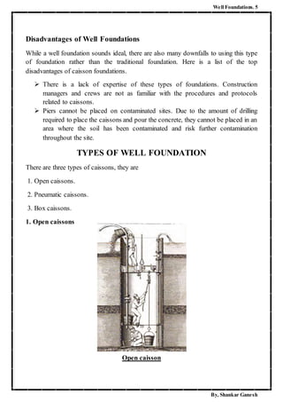
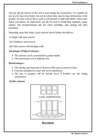
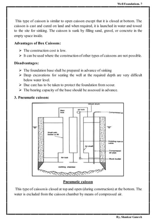
SlideShare a Scribd company logo
A mini project carried out through internship training at
During
By
DEPARTMENT OF CIVIL ENGINEERING
MAHATMA GANDHI INSTITUTE OF TECHNOLOGY
(Affiliated to Jawaharlal Nehru Technological University, Hyderabad)
Approved by AICTE, New Delhi
Sponsored by Chaitanya Bharathi Educational Society
GANDIPET, HYDERABAD– 500075. A.P. (INDIA)
www.mgit.ac.in
MAHATMA GANDHI INSTITUTE OF TECHNOLOGY
(Affiliated to Jawaharlal Nehru Technological University, Hyderabad)
Approved by AICTE, New Delhi.
DEPARTMENT OF CIVIL ENGINEERING
CERTIFICATE
This is to certify that this report “CONSTRUCTION OF WELL
FOUNDATIONS” is a bonafide record of work done by
RAVIKOTI SHANKAR GANESH KUMAR through internship training at
PANCHAYAT RAJ DEPARTMENT, MEDAK and submitted for Mini
Project to the Department of Civil Engineering, Mahatma Gandhi Institute
of Technology, Gandipet, Hyderabad.
V. VenkatRamayya Dr. K.V. Ramana Reddy
Asst. Prof., Civil Engineering Department, HoD, Civil Engineering Department,
Mahatma Gandhi Institute of Technology Mahatma Gandhi Institute of Technology
GOVERNMENT OF TELANGANA
OFFICE OF THE EXECUTIVE ENGINEER PIU DIVISION MEDAK
CERTIFICATE
This is to certify that Mr RAVIKOTI SHANKAR GANESH KUMAR bearing Roll
no. 13261A0146 studying B.Tech IV year, Civil Engineering in Mahatma Gandhi
Institute of Technology, Gandipet, Hyderabad, had undergone internship in Panchayat
Raj Engineering department(PIU Division), Medak from 20/05/2016 to 04/06/2016
during the summer vacation. The student has been trained in the area of
“CONSTRUCTION OF WELL FOUNDATIONS” during the internship.
INDEX
Page No.
1. Acknowledgement 01
2. Preface 02
3. Abstract 03
4. Introduction
a. Historicalbackground 04
b. What are wellfoundations? 04
c. Advantages and Disadvantages 04 - 05
d. Types of Well foundations 05 - 08
e. Shapes of Well Foundation 08 - 10
f. Components of Well Foundation 10 - 11
5. Procedure followedin site.
a. Layout 13 - 14
b. Fabricationof Cutting Edge 14 - 17
c. Constructionand pitching of well curb 17 - 20
d. Constructionof Steining 20 - 23
e. Well sinking 23 - 24
f. Bottomplugging, Sand filling, Top plugging 24 - 27
6. Problems encounteredand their solutions 28 - 34
7. Overall review 35 - 36
Well Foundations. 1
By, Shankar Ganesh
ACKNOWLEDGEMENT
It was great experience working in the department of Panchayat Raj, Medak under the
guidance of very encouraging and enthusiastic engineers.
From the bottom of my heart, I would like to thank
Sanjeev Rao
(Superintending Engineer, Panchayat Raj, Medak)
C. Venkateshwarulu
(Executive Engineer, PR, Medak Division)
P. Jagadeshwar
(Dy. Executive Engineer, PR, Medak)
Panduranga Reddy
(Assistant Engineer, PR, Medak)
for giving me an opportunity to do internship within the organization. For me it was a
unique experience to be in Medak and to study an interesting topic, Well
Foundations. I also would thank all the people who worked in the site. With their
patience and openness they created an enjoyable working environment. Furthermore, I
want to thank R. Yadagiri, site engineer, with whom I did the fieldwork.
I feel honour to express my sincere gratitude to
Dr. G. Chandra Mohan Reddy
(Principal, MGIT)
Dr. K. V. Ramana Reddy
(HoD, CED, MGIT)
Further, I would like to thank my guide for the internship
V. Venkata Ramayya
(Asst. Prof., CED, MGIT)
for sharing his knowledge and helping me a lot in preparing this Internship report.
- ShankarGanesh
Well Foundations. 2
By, Shankar Ganesh
PREFACE
In this report I would like to share my experience and knowledge earned during my
Industry oriented mini project (Internship). I’ve done my internship in Panchyat Raj,
Medak district. I worked upon a bridge construction that is taken up by PR, Medak.
The bridge was planned to construct on Gangamma vagu, R/f Medak – Bodhan PWD
Road to Polkampet @ 6.5 K.M., Medak mandal, Medak district.
The length of the bridge to be constructed was 120.690 meters. Small bridges will be
generally constructed on shallow isolated foundations. There will be continuous flow
of Vagu throughout the year. Hence, shallow foundations may not suit here.
Moreover, the bottom bed of the Vagu has very low Soil Bearing Capacity (S.B.C.).
Soft Disintegrated Rock (S.D.R.) occurs at a greater depth of 7m – 8m from the river
bed.
So, to overcome the above stated problems, it is recommended to constructa bridge on
well foundations. The well foundations are laid by following sinking of well
mechanism.
Well Foundations. 3
By, Shankar Ganesh
ABSTRACT
Well foundations had their origin in India and have been used for Hundreds of years,
for providing deep foundations, for important buildings and structures. The technique
of sinking masonry wells for drinking water is very ancient. Same technique was used
for construction of foundation wells in the earlier stage. Well foundations were freely
used during the Mughal period and many of the Mughal monuments including the Taj
Mahal have got well foundations .The Mughal used well foundation for bridges across
Major River also. But these bridges were washed away within a few years as the
mechanism of scour was not understood. In spite of the excellent development of
technology on well foundations there are still some areas where engineers face
difficulty while sinking of wells, some of which are stated in this paper from the direct
experience. Well foundations are quite appropriate foundations for alluvial soils in
rivers and creeks where maximum depth of scour can be quite large. In India
technology of well foundation for design and construction is quite well developed.
Still there are situations where serious problems are encountered at site during
construction of well foundations.
Well Foundations. 4
By, Shankar Ganesh
INTRODUCTION
Historical Background of Well Foundations:
Well Foundations had their origin in India and have been used for hundreds of years
for providing deep foundations for important buildings and structures.
One of the Seven Wonders of the World, Taj Mahal was constructed upon well
foundations. Well foundations were used fpr the first time for important irrigation
structures on the Ganga Canal at Roorkee, constructed in the middile of 19th century.
What are Well Foundations?
Well Foundations are a type of deep foundations which are generally provided below
the water level for bridges. These are constructed by sinking Cassions from the surface
of either land or water to some desired depth. Well foundations provide a solid and
massive foundation for heavy loads and are useful in situations where the loads have
to be transferred to a soil stratum deep below.
Advantages of well foundations
There are many advantages in installing a well foundation. Here is a list of the top
advantages of the well foundations.
 It is easily adaptable to varying site conditions. This means that no matter where
the structure is being constructed, caissons can be easily put in place. The
hardest part of placing them is the drilling of the holes.
 They are very economical. The cost to drill and install the caissons is minimal
when compared to the cost to lay a traditional foundation.
 Piers minimize the need for pile caps. Because the piers are filled with concrete,
pile caps are really not necessary.
 The well foundation will reduce vibrations and has slightly less noise. Since the
foundation is based on piers, there are fewer vibrations that will upset the
structure.
 Depth of the foundation can be decided as the sinking process.
 They can withstand large lateral loads and moments that occur in the case of
bridge piers, abutments, tall chimney’s and towers.
Well Foundations. 5
By, Shankar Ganesh
Disadvantages of Well Foundations
While a well foundation sounds ideal, there are also many downfalls to using this type
of foundation rather than the traditional foundation. Here is a list of the top
disadvantages of caisson foundations.
 There is a lack of expertise of these types of foundations. Construction
managers and crews are not as familiar with the procedures and protocols
related to caissons.
 Piers cannot be placed on contaminated sites. Due to the amount of drilling
required to place the caissons and pour the concrete, they cannot be placed in an
area where the soil has been contaminated and risk further contamination
throughout the site.
TYPES OF WELL FOUNDATION
There are three types of caissons, they are
1. Open caissons.
2. Pneumatic caissons.
3. Box caissons.
1. Open caissons
Open caisson
Well Foundations. 6
By, Shankar Ganesh
The top and the bottom of the well is open during the construction. It is suitable for
use in soft clays (river beds), but not for where there may be large obstructions in the
ground. An open caisson that is used in soft grounds or high water tables, where open
trench excavations are impractical, can also be used to install deep manholes, pump
stations and reception/launch pits for micro tunnelling, pipe jacking and other
operations.
Depending upon their shape, open caissons can be further classified as,.
(i) Single wall open caisson
(ii) Cylindrical open caisson
(iii) Open caisson with dredging wells.
Advantages of Open Caissons:-
 The caissons can be constructed to greater depths.
 The construction cost is relatively low.
Disadvantages:-
 The clearing and inspection of bottom of the caisson cannot be done.
 Concrete seal placed in water will not be satisfactory.
 The rate of progress will be slowed down if boulders are met during
construction.
(2) Box caisson:
Box caisson
Well Foundations. 7
By, Shankar Ganesh
This type of caisson is similar to open caisson except that it is closed at bottom. The
caisson is cast and cured on land and when required, it is launched in water and towed
to the site for sinking. The caisson is sunk by filling sand, gravel, or concrete in the
empty space inside.
Advantages of Box Caissons:
 The construction cost is low.
 It can be used where the construction of other types of caissons are not possible.
Disadvantages:
 The foundation base shall be prepared in advance of sinking
 Deep excavations for seating the well at the required depth are very difficult
below water level.
 Due care has to be taken to protect the foundation from scour.
 The bearing capacity of the base should be assessed in advance.
3. Pneumatic caisson:
Pneumatic caisson
This type of caissonis closed at top and open (during construction) at the bottom. The
water is excluded from the caisson chamber by means of compressed air.
Well Foundations. 8
By, Shankar Ganesh
Advantages of Pneumatic Caissons:
 Control over the work and preparation of foundation for the sinking of caisson
are better since the work is done in the dry conditions.
 The caisson can be sunk vertically as careful supervision is possible.
 The bottom of the chamber can be sealed effectively with concrete as it can be
placed dry.
Disadvantages:
 Construction cost is quite high.
 The depth of penetration below water is limited to about 35m.Higher pressure
are beyond the endurance of the human body
SHAPES
There are different shapes of well foundations in cross sectional view. Following are
the different shapes.
1. Circular well
2. Double – D well
3. Double Octagonal well
4. Twin Circular well
5. Rectangular well
Circular wells:
Circular Well
Most common shape of well foundations preferably used everywhere is circular wells.
It is featured with very high structural strength and is convenient in sinking;
additionally the chances of tilting are exclusively less. These circular well foundations
Well Foundations. 9
By, Shankar Ganesh
are perfectly suitable for piers of the single-line railway bridges and the double-lane
road bridges. But for excessively lengthier piers it turns out to be uneconomical. Thus,
the maximum diameter of circular well is principally limited to 9m.
Double-D wells:
Double-D wells
These wells are usually employed on the piers and abutments of the bridges that are
excessively long to be accommodated on a circular well of 9m diameter. These wells
can be sunk easily. But considerable bending moments are introduced in the steining
because of difference in pressure between outside and inside of the well. Additionally
the square corners at the partition well provide maximum resistance to sinking.
Double-octagonal wells:
Double-octagonal wells
These wells are considered to be better than Double-D wells in numerous aspects.
Most preferably the square corners are eliminated such that bending stresses are
reduced considerably. Additionally these wells provide higher resistance against
sinking than double-D wells because of increased area.
Well Foundations. 10
By, Shankar Ganesh
Twin- circular wells:
Twin- circular wells
Two circular identical wells are sunk very close to one another such that they are held
with a common well-cap. These wells are sunk simultaneously, adjacently. These
wells are preferable where the length of pier cannot be accommodated on a double-D
or double-octagonal well. These wells are found advantages where the depth of
sinking is smaller and the soil strata bearing capacity is greater.
Rectangular wells:
Rectangular wells
Rectangular wells are principally employed on bridge foundations with depths up to
7m-8m. In case of larger foundations double-rectangular wells can be used. The
loading stresses at the steining are very high in rectangular wells.
COMPONENTS OF WELL FOUNDATION
1. Steining:
It is the wall or shall of the well, made of R.C.C. and which transfer the load to the
curb. It acts as an enclosure for excavating the soil for the penetration of well.
2. Curb:
It is a R.C.C. ring beam with steel cutting edge below. The cross-section of the curb is
wedge shaped which facilitates the sinking of the well. The curb supports well
steining. The curb is kept slightly projected from the steining to reduce the skin
friction.
3. Cutting edge:
It is the lowest part of the well curb which cuts the soil during sinking.
Well Foundations. 11
By, Shankar Ganesh
Components of Well foundations
4. Bottom plug:
After completion of well sinking the bottom of well is plugged with concrete. The
bottom plug which is confined by the well curb acts as a raft against soil pressure from
below.
5. Back fill:
The well is dewatered after setting of the bottom plug and it is backfilled by sand or
excavated material.
6. Top plug:
It is a concrete plug provided over the filling inside the well.
7. Well cap:
It is a R.C.C. slab provided at the top of stening to transmit the load of superstructure
to the stening and over which pier is laid. The minimum thickness of the slab is about
750 mm.
Well Foundations. 12
By, Shankar Ganesh
CONSTRUCTION METHODOLOGY FOR WELL FOUNDATION
FOLLOWED IN THE SITE
Let us know discuss how the well foundations are constructed in the site.
The bridge was designed to be constructed upon 8 piers or abutments.
Out of which 7 piers were constructed on well foundations and 1 abutment was
constructed on shallow isolated foundation.
The important features of the bridge are
Length of the bridge – 120.960 metres
Carriageway width – 7.50 metres (without footpaths)
Type of bridge – High Level Bridge
Well Foundation details:
Shape – Circular Well
Outer diameter – 7.0 metres
Inner diameter – 5.8 metres
Steining thickness – 0.6 metres
Well curb height – 1.3 metres
Angle of Cutting edge – 31 degrees
Grade of steining concrete – M25
Concrete Mix for Foundation
Concrete mix design was carried out as per RVNL Specification and IS 10262. The
concrete was designed to achieve desired degree of workability for specific grade of
concrete to facilitate concreting operation. Trials was conducted and cubes were cast,
tested before acceptance of Design mix.
Grade of Concrete for Well Curb: M 35
Grade of Concrete for Well Steining: M 25
Grade of Concrete for Bottom Plugging: M 25
Grade of Concrete for Top Plug: M 25
Grade of Concrete for Well Cap: M 35
Well Foundations. 13
By, Shankar Ganesh
Following steps were followed in the construction of well foundations.
1. Layout
2. Fabrication and construction of Cutting Edge
3. Construction and pitching of Well Curb
4. Construction of Steining
5. Well Sinking
6. Construction of Bottom Plug
7. Sand Filling
8. Construction of Top Plug
Let us discuss each step in detail.
LAYOUT
The accurate layout of centre line of the bridge and the location of piers and abutments
is of paramount importance. Till the accurate layout of the bridge as well as various
piers and abutments location is made, it will not be possible to install or go for
construction of a well foundation, so it is a very important factor.
The commonly adopted method for laying out the station point line at right angles to
the centre line of the bridge on the high bank on one side of the proposed bridge or
anywhere between the abutments where level ground may be available.
In this particular method masonry pillars are constructed on the line to serve as station
points for checking the location of piers.
It can be seen in the figure, the station points 1 2 3 4 5. For each bridge pier two pillars
are located such that by setting theodolites at each of these pillars at a given
inclination to the station point line. The centre line of the pier is identified by the point
of intersection of the lines of collimation.
Let, this line of collimation is making an angle of 45 with the line which is joining the
station points. So, a theodolite can be used to make an angle which is predefined, let,
in this case as it is shown in the figure 45, so to have a line of collimation at 45 degree
from one station point as well as from other station point.
Well Foundations. 14
By, Shankar Ganesh
So, wherever they intersect gives one point for laying out the bridge centre line,
likewise various points on this particular line are established and the location of piers
are marked on the ground.
CUTTING EDGE
After locating the points cutting edge is fabricated and placed at the specified points.
Let us deal with how cutting edge was fabricated in the site.
Following table details about the cutting edge dimensions and all.
S.No. Description Location Used
1 Angles 150 X 150 X 12 Outer Tee
2 Angles 150 X 150 X 12 Brackets
3 MS Plate 20 mm Cutting Edge Plate
Well Foundations. 15
By, Shankar Ganesh
The cutting edge shall be fabricated with mild steel structural sections and plated of
specified grade as per approved drawings. Fabrication of cutting edge may be carried
out at site or at a shop. The cutting edges shall be fabricated in pieces / segments.
During the process of fabrication and handling / erection suitable temporary supports
are to provided / maintained to render rigidity and to keep shape of the segments and /
or parts thereof. Number of segments shall be decided prior to start of fabrication
depending on easement of handling and transport. Checks are to be made on
dimension and shape of the segments.
For bending the structural members, V – cuts may be made and after bending such V –
cuts are to be closed by welding. Joints in the length of structural sections shall be
made with fillet welds with a single cover plate or as shown in the drawings.
Cutting Edge
Tools and Plants for Cutting Edge Fabrication:
 Rolling machine / Hydraulic Jacks for bending.
 Drilling machine.
 Electrical welding machine.
 Pug cutting machine.
 Hand grinding machine / Table mounted wheel grinder.
Well Foundations. 16
By, Shankar Ganesh
Fabrication of Cutting Edge:
Working Platform: The working platform is made up of plain steel plates welded to
each other’s over levelled concrete surface at the central fabrication yard. The
fabrication of the cutting edge involves the following steps.
Preparation of back angles:-
 Layout of cutting edge is marked on working platform.
 Angle sections are cut of required length.
 A pair of angles shall be placed together back to back and shall be bent to the
required radius by hydraulic press on bending platform and same shall be
checked with curvature template and corrected if required.
Preparation of MS plates:-
 The required width and length of the plate as per drawing shall be marked and
cut using pug cutting machine.
 Plate shall be bent to the required radius.
 The same shall be checked with curvature template and corrected if required.
Preparation of Brackets:-
 Layout of Brackets is marked on working platform.
 Angle sections are cut of required length.
 The angles are welded as per the drawing, the same is to be checked on the
layout platform and corrected if required.
Assembly:-
 The MS plate shall be connected with angle by tack weld and checked for the
required radius. After final checking welding shall be done as mentioned.
 Stiffeners shall be welded in required spacing.
 Bent plates shall be welded as per the drawing.
 Fabricated pieces of cutting edge segments are to be shifted to site by truck of
trailer.
Prefabricated segments of the cutting edges shall be brought to site of work and
assembled at the well location. Segments of cutting edge shall be erected on firm &
levelled ground or prepared island base at the predetermined position. Temporary
support as required to facilitate assembly and keeping the entire assembly in true
shape shall be provided. Placement of the segments shall be made with the help of a
crane on wooden sleepers placed along the periphery of the cutting edge.
Well Foundations. 17
By, Shankar Ganesh
Dimensions, shape & size, alignment and level shall be checked by the Engineer and
splice plate shall be welded at every joints and final welding shall be completed.
WELL CURB
The following steps are involved in construction of well curb.
1. Placement of Cutting Edge.
2. Fixing of formwork and Rebar.
3. Concreting.
4. Curing.
5. Removal of formwork.
6. Sinking of Well Curb.
Placement of Cutting Edge:
 Accurate survey shall be carried out for fixing the well locations.
 Permanent reference pillars are to be provided at the four sides i.e. along and
across centre line of bridge.
 The ground is levelled by removing the top loose soil and compacted and
rescued levels are recorded jointly.
 Centre point of well is marked.
 The fabricated cutting edge segments shall be shifted to site by truck / trailer up
to the jetty location the same shall be shifted to well location by barge.
 Wooden sleepers are placed at a interval of 1.50m along the circumference of
the cutting edge.
 Cutting Edge is placed over wooden sleepers using crane aligned and joined
with respect to centre lines. After alignment joints are to be welded.
 Level and alignment of cutting edge shall be checked finally using the
established horizontal controls. If required minor rigid bracing are provided for
maintaining proper level.
 Dowel bars are welded to Cutting Edge.
Well Foundations. 18
By, Shankar Ganesh
Well Curb
Formwork and Rebar’s Fixing:
Inner formwork:
 Inner form panels are first cleaned and standard form releasing agent is applied
on the surface.
 To make the shutter joints leak proof suitable foam sheets between shuttering
joints and/or masking tape at joints are used to seal the joints.
 Inner formwork shall be erected and all the form panels shall be joined to form
the true shape as per the concrete profile, horizontal and diagonal supports
erected. The erection of inner formwork shall be as per enabling drawing issued
by enabling dept. The formwork shall be handled by crane.
Fixing of Rebar:
 Rebar’s are cut and shaped at the central rebar yard as per the approved bar
bending schedule and transported to site using truck/trailer up to the jetty
location. The bars shall be transported to well location by barge.
Well Foundations. 19
By, Shankar Ganesh
 Adequate number of 75 mm cement concrete cover blocks shall be placed to
maintain cover along the periphery of formwork and also at the bottom to
maintain specified cover.
 Outer vertical bond bars shall be welded with angle. All other reinforcement
bars along with any stiffeners / spacers are fixed in position as per drawing and
approved bar bending schedule.
 The rebar are checked jointly with Engineer’s representative.
Fixing of Outer Formwork:
 Before fixing of outer formwork entire floor area shall be cleaned.
 Form panels shall be fixed as per drawing.
 To ensure the leak proof joints, thin foam packing shall be provided between
adjacent shuttering panels. Alternatively masking adhesive tape shall be applied
over the shuttering joints.
 Access platform using landing mats are provided for inspection and concrete
purpose.
 Coil anchors shall be embedded in concrete, at appropriate locations for erection
of shuttering for the next lift.
 Final checking shall be done jointly with Engineers representative.
Concreting:
 Concrete shall be done by static concrete pump located on barge.
 Concrete shall be transported from the nearest batching plant through transit
mixers and ferried to well location by the barge.
 Concrete shall be placed in a continuous pour. Shear key shall be provided at
each lift construction joint.
 Adequate illumination arrangement shall be ensured to provide safe working
during night hours to satisfy supervision and safety requirements.
Curing:
 Curing shall be done by spraying water on surface covered with hessian cloth.
 Curing can also be done by using approved curing compound.
De-shuttering and Gauge marking:
 Outer formwork shall be removed within 24 hours.
 Inner formwork shall be removed after 72 hours
Well Foundations. 20
By, Shankar Ganesh
 Gauge marking shall be done along both axes at four outer face location of the
well by using template.
Sinking of Well Curb:
 After removal of inner form panel, gunny bags filled with sand shall be placed
in between wooden sleepers along the periphery at the bottom of cutting edge.
 Grounding of the curb shall be done after removing the inner forms.
 The curb is sunk to the ground level by manual dredging in the dredge hole.
When the dredging is partially complete, the loose material is removed from the
dredge hole using the plate gran and is dumped outside the area of well, later
this dredged material shall be disposed to nearby area provided by engineer.
 The sinking history would be recorded in the format as provided in the technical
specification (Appendix 1200/I, MoRT&H).
 The sinking level is monitored at regular intervals of 500mm.
WELL STEINING AND SINKING
The steps involved in the Steining are:-
1. Inner and outer formwork.
2. Rebar fixing.
3. Concreting and curing.
4. Sinking.
Inner and outer formwork:
 Inner and outer formwork is made of 4mm MS Steel plates and rolled steel
sections fabricated for a lift of 2.5m.
 3.0 mm thick foam sheet adhesive tape at the location of joints are used to seal
the joints.
 Form releasing agent shall be applied on the inner face of the panels coil
anchors/ nuts, which are to be embedded in concrete for erection of lift are fixed
at appropriate locations.
 The inner form panels are erected for the subsequent lifts, the form work is
supported on the coil nut arrangement with the bottom lift concrete. The rebar
are fixed in position followed by fixing of outer formwork. Over the inner
Well Foundations. 21
By, Shankar Ganesh
formwork, rigid horizontal supports shall be provide to keep the shutters profile
and it shall be used for platform after placing the landing mats
 Final checking of formworks shall be carried by jointly with Engineers rep.
Rebar fixing:
 Rebar are cut and bent at the central rebar yard as per the approved bar bending
schedules and transported from the yard by truck/ trailer.
 Re bars are fixed as per drawing and schedule.
 Adequate cement concrete cover blocks shall be provided along the periphery of
the formwork to maintain the cover of rebar.
Rebar of Steining
Concreting and curing:
 Placement of concrete shall be done as described for the well curb.
 Shear key shall be provided at each construction joints.
 The concrete surface shall be cleaned thoroughly and surface preparation is
made to receive the succeeding layer of concrete.
Well Foundations. 22
By, Shankar Ganesh
 Before casting the last lift of steining it shall be checked and verified for
appropriate steel for false steining, grooves for precast beams to support false
work for well cap.
Concreting the Well Steining
De - shuttering:
The inner and outer form panels are removed after 12 hours of the concrete finished
time.
Steining Sinking:
Following the de shuttering of steining lift, gauge marking is carried out at both axes
in line with well curb marking and reference height is marked on the wall surface. The
sinking operation would be started after 16 hrs of concreting for steining.
Well Foundations. 23
By, Shankar Ganesh
SINKING OPERATION
Sinking of wells shall be carried out by dredge hole method by using the following
steps:
 The sinking operation involves lowering of the well by dredging in the dredge
hole.
 Plate grab shall be used in case of soft strata like sandy silt, soft clay, dense
sand, etc.
 In case of hard clay, stiff clay strata heavy-duty chisel shall be used, followed
by dredging using Tyne grab.
 Levels and alignment of well shall be checked regularly interval of 1hr of
sinking to observe the tilt and shift of the well at closer intervals if the visual
observation demands.
 Sinking operation shall be preferably carried out round the clock under skilled
supervision.
 Dredged materials shall be disposed off to locations designated by the Engineer.
 The above cycle of well steining and sinking shall be repeated up to the last lift
of the well until well reaches to the founding level.
Open Dredgering
Well Foundations. 24
By, Shankar Ganesh
PRECAUTIONS DURING SINKING
 When the wells have sunk close to each other and clear distance between them
is not greater than the diameter of wells, sinking shall be taken up on all wells
and they shall be sunk alternately.
 Before seasonal floods all wells on which sinking is in progress shall be to
sufficient depths below the designed scour level.
 Very deep sump shall not be made below the well curb. The depth of sump shall
not exceed 3.0m below the level of cutting edge unless otherwise specifically
permitted by Engineer.
 Dewatering is avoided if sand blows are expected.
PLUGGING OF WELL AND WELL CAP
Bottom plug:
Once the cutting edge has reached the founding level as shown in the drawing or as
decided by the engineer, a sump of required shape and shape as shown in the drawing
or decided by the Engineer shall be formed. It is desirable to have a good idea of the
shape of the sump either by probing or by sending divers.
After completion soundness test of bottom plug filling inside the well shall commence
after a period of 3 days.
Sand filling:
After the bottom plug and waiting period is over, sand filling shall be started. Good
quality sand shall be filled in dredge hole after 3 days of bottom plug concrete up to
required level.
After sand has been filled in the well, water remaining on top of the sand shall be
bailed outers. Top level of sand to be checked and top plug / intermediate plug of
required grade of concrete and thickness shall be laid as shown in the drawing, and
balance work of well cap shall be taken up.
Well Foundations. 25
By, Shankar Ganesh
Bottom Plugging and Sand Filling
Well Cap Casting:
Well cap reinforcement
Layout for the well cap reinforcement shall be given on top plug and well steining
concrete. Already cut, bent and shifted reinforcement shall be tied in position as per
approved drawings. Clear cover blocks made from same grade of concrete as that of
well cap shall be tied to reinforcement.
Well Foundations. 26
By, Shankar Ganesh
Top Plug
Well cap formwork
The normal streel forms shall be the fixed in position as well cap outer side forms as
per drawing. Supporting arrangement shall be done as per drawing. Well cap
shuttering shall be done as per shape and size of well where false steining is not there.
Well cap concrete
The concrete mixed at central batching plant shall be delivered through transit mixers.
Concrete shall be placed through Concrete pumps. Concrete shall be vibrated with
high frequency needle vibrators. It shall be ensured that concreting is done
continuously and completed in a single pour without any cold joint.
Well Foundations. 27
By, Shankar Ganesh
Pier over Well Foundation
Well Foundations. 28
By, Shankar Ganesh
PROBLEMS ENCOUNTERED AND THEIR SOLUTIONS
Tilts and Shifts
The main objective in well sinking is to sink it straight and at the correct position. In
practice, however, this is not easy to achieve. It is, therefore, important that adequate
precautions are taken to avoid any tilt or shift during sinking. Also, in case any tilt or
shift is observed at any stage, proper records should be maintained and measures to
rectify the same taken.
The following precautions are useful in avoiding tilts and shifts in wells:
 The outer surface of the well curb and well steining must be regular and as
smooth as possible.
 The radius of the well curb should be kept about 20 mm to 40 mm larger than
the outer radius of the well steining. The well curb thus projects out from the
well steining. This projection should be equal and uniform on all sides.
 Cutting edge should be of uniform thickness and sharpness.
 Dredging should be done uniformly and on all sides of the well. For a twin well,
dredging should be done in both dredge holes uniformly.
 Tilt and shift of a well, if any, should be carefully checked and properly
recorded. The well is constructed in stages and correct measurements of tilt and
shift are the most important field observations required during well sinking. In
case a well shows a tendency to tilt, dredging should be done not bring about
any improvement, the sinking should be suspended and necessary measures to
rectify tilts and shifts should be taken before resuming the sinking.
The following methods are found useful in rectifying tilt and shift. Any of these
methods may be adopted, either separately or in combination.
Well Foundations. 29
By, Shankar Ganesh
1. Controlled dredging
The dredging is done more on the higher side. This method is effective in the
initial stages of sinking, but as the sinking processes, regulation of grabbing becomes
more difficult.
Dredging with hooking
Well Foundations. 30
By, Shankar Ganesh
2. Eccentric Loading
Kentledge is normally required to accelerate the process of well sinking. To
provide greater sinking effort on higher side of the well, eccentric loading is provided
through a suitable platform.
Eccentric Loading
Well Foundations. 31
By, Shankar Ganesh
3. Pulling the well
Pulling the well on the higher side is also effecting in rectifying tilt. The pull
can be applied by winding a steel wire rope round the well and tying it to a tackle
anchor. To avoid damage to the well steining, wooden sleepers should be used during
pulling.
Pulling the Well
Well Foundations. 32
By, Shankar Ganesh
4. Pushing the well
Push to the well can be applied on the lower side of the well to rectify tilt. Push
can be applied by strutting the well against a dead man or against a vertically sunk
well through a hydraulic jack.
Pushing by Jacks
Well Foundations. 33
By, Shankar Ganesh
5.Water jetting or digging pit on the higher side
Water jets are useful in the sinking of a well because by jetting, friction is
reduced. Water jets can be used on the higher side of well reduces friction and thus
rectifies the tilt. Excavation of pit on the higher side is also useful in reducing friction
on the higher side.
Digging Pit
Well Foundations. 34
By, Shankar Ganesh
6. Providing obstacles below Cutting Edge
Temporary obstacles in the form of wooden sleepers, sand bags or suitable
hooks placed below the cutting edge on the lower side of the well, are useful in
avoiding further tilt of the well, while other measures to rectify tilt are being adopted.
Obstruction by sleeper piece
Well Foundations. 35
By, Shankar Ganesh
OVERALL REVIEW
Till now we discussed what well foundations are! Different shapes, components,
advantages and disadvantages of well foundations were discussed. Different types of
well foundations and their constructions procedures were discussed.
All possible problems that may encounter in sinking of the well were discussed. We
also discussed their solutions in detailed manner.
Let us revise construction procedure of well foundations briefly, using the following
flow chart in the next page.
Well Foundations. 36
By, Shankar Ganesh
Well Curb De-shuttering
Shuttering of Well Curb
Layout Cutting Edge RebarFixing Outer – 24 hours
Concreting Inner – 72 hours
Curing
Well Steining
Shuttering (2 metres)
Rebar Fixing
Concreting
Curing
De-Shuttering
When required Sinking of Well
Bottom Plug By, open dredging
depth is reached
Sand Filling
Top Plugging
Pier Construction
on Well Foundation

More Related Content

What's hot

SINKING , TILTING AND DISEASE OF CAISSON
SINKING , TILTING AND DISEASE OF CAISSONSINKING , TILTING AND DISEASE OF CAISSON
SINKING , TILTING AND DISEASE OF CAISSON
jay lad
 
Vacuum dewatering
Vacuum dewateringVacuum dewatering
Vacuum dewatering
Aglaia Connect
 
Caisson
CaissonCaisson
Earthen Dam
Earthen DamEarthen Dam
Diaphragm wall: Construction and Design
Diaphragm wall: Construction and DesignDiaphragm wall: Construction and Design
Diaphragm wall: Construction and Design
Umer Farooq
 
Jacketing
JacketingJacketing
Jacketing
SHAIKH ARSHAD
 
Canal Fall
Canal FallCanal Fall
Canal Fall
GAURAV. H .TANDON
 
types of canals
types of canals types of canals
types of canals
number113
 
Pile foundation
Pile foundationPile foundation
Pile foundation
ghildiyal8811
 
Caissons
Caissons Caissons
Tunneling & Drilling Equipments
Tunneling & Drilling EquipmentsTunneling & Drilling Equipments
Tunneling & Drilling Equipments
Rajarshi Patty
 
Soil stabilisation (1)
Soil stabilisation (1)Soil stabilisation (1)
Soil stabilisation (1)
Safiullah Khan
 
Diversion head works
Diversion head worksDiversion head works
Canal outlets and modules
Canal outlets and modulesCanal outlets and modules
Canal outlets and modules
bhalinder singh
 
river training work
river training workriver training work
river training work
Vishal Chaudhari
 
Dynamic Pile Formulae
Dynamic Pile FormulaeDynamic Pile Formulae
Dynamic Pile Formulae
Kriti Singh
 
Chapter 3 shallow foundations
Chapter 3 shallow foundationsChapter 3 shallow foundations
Chapter 3 shallow foundations
KHUSHBU SHAH
 
Types of samplers used in soil sampling
Types of samplers used in soil samplingTypes of samplers used in soil sampling
Types of samplers used in soil samplingAna Debbarma
 
Canal alignment
Canal alignmentCanal alignment
Canal alignment
Naveenaa
 
Intze tank design
Intze tank designIntze tank design
Intze tank design
Koppolu Abishek
 

What's hot (20)

SINKING , TILTING AND DISEASE OF CAISSON
SINKING , TILTING AND DISEASE OF CAISSONSINKING , TILTING AND DISEASE OF CAISSON
SINKING , TILTING AND DISEASE OF CAISSON
 
Vacuum dewatering
Vacuum dewateringVacuum dewatering
Vacuum dewatering
 
Caisson
CaissonCaisson
Caisson
 
Earthen Dam
Earthen DamEarthen Dam
Earthen Dam
 
Diaphragm wall: Construction and Design
Diaphragm wall: Construction and DesignDiaphragm wall: Construction and Design
Diaphragm wall: Construction and Design
 
Jacketing
JacketingJacketing
Jacketing
 
Canal Fall
Canal FallCanal Fall
Canal Fall
 
types of canals
types of canals types of canals
types of canals
 
Pile foundation
Pile foundationPile foundation
Pile foundation
 
Caissons
Caissons Caissons
Caissons
 
Tunneling & Drilling Equipments
Tunneling & Drilling EquipmentsTunneling & Drilling Equipments
Tunneling & Drilling Equipments
 
Soil stabilisation (1)
Soil stabilisation (1)Soil stabilisation (1)
Soil stabilisation (1)
 
Diversion head works
Diversion head worksDiversion head works
Diversion head works
 
Canal outlets and modules
Canal outlets and modulesCanal outlets and modules
Canal outlets and modules
 
river training work
river training workriver training work
river training work
 
Dynamic Pile Formulae
Dynamic Pile FormulaeDynamic Pile Formulae
Dynamic Pile Formulae
 
Chapter 3 shallow foundations
Chapter 3 shallow foundationsChapter 3 shallow foundations
Chapter 3 shallow foundations
 
Types of samplers used in soil sampling
Types of samplers used in soil samplingTypes of samplers used in soil sampling
Types of samplers used in soil sampling
 
Canal alignment
Canal alignmentCanal alignment
Canal alignment
 
Intze tank design
Intze tank designIntze tank design
Intze tank design
 

Similar to Well foundations

Well foundation pdf
Well foundation pdfWell foundation pdf
Well foundation pdf
Alauddin aziz khan
 
DIFFERENT TYPES OF Well foundation & THEIR RELATIVE MERITS &DEMRITS
DIFFERENT TYPES OF Well foundation & THEIR RELATIVE MERITS &DEMRITSDIFFERENT TYPES OF Well foundation & THEIR RELATIVE MERITS &DEMRITS
DIFFERENT TYPES OF Well foundation & THEIR RELATIVE MERITS &DEMRITS
Asaru Champ
 
1619929813526_College Deep Well Foundation Project.pptx
1619929813526_College Deep Well Foundation Project.pptx1619929813526_College Deep Well Foundation Project.pptx
1619929813526_College Deep Well Foundation Project.pptx
AkshayGhorpade19
 
IVRCL REPORT Atishay TYagi (UPES)
IVRCL REPORT Atishay TYagi (UPES)IVRCL REPORT Atishay TYagi (UPES)
IVRCL REPORT Atishay TYagi (UPES)ATISHAY TYAGI
 
Design of Intze Water Tank by Using Staad Pro for Hathipur Village
Design of Intze Water Tank by Using Staad Pro for Hathipur VillageDesign of Intze Water Tank by Using Staad Pro for Hathipur Village
Design of Intze Water Tank by Using Staad Pro for Hathipur Village
IRJET Journal
 
JEEVA.pptx
JEEVA.pptxJEEVA.pptx
JEEVA.pptx
SachinHM14
 
Major Project Presentation about OHT 2.pptx
Major Project Presentation about OHT 2.pptxMajor Project Presentation about OHT 2.pptx
Major Project Presentation about OHT 2.pptx
mhk98973
 
PROJECT DOCUMENT OF PERVIOUS CONCRETE
PROJECT DOCUMENT OF PERVIOUS CONCRETEPROJECT DOCUMENT OF PERVIOUS CONCRETE
PROJECT DOCUMENT OF PERVIOUS CONCRETE
G.Ajith Kumar
 
101under water conustrution.pptx
101under water conustrution.pptx101under water conustrution.pptx
101under water conustrution.pptx
MEHALAS3
 
Project report on self compacting concrete
Project report on self compacting concreteProject report on self compacting concrete
Project report on self compacting concreterajhoney
 
CONSTRUCTION OF OVERHEAD BRIDGE
CONSTRUCTION OF OVERHEAD BRIDGECONSTRUCTION OF OVERHEAD BRIDGE
CONSTRUCTION OF OVERHEAD BRIDGEAnkit Gautam
 
Soil nailing/Soil Reinforcement Technique
Soil nailing/Soil Reinforcement TechniqueSoil nailing/Soil Reinforcement Technique
Soil nailing/Soil Reinforcement Technique
Anandu Aravind
 
site report
site reportsite report
site report
dhirazain
 
UMAID IQBAL SEMINAR.pptx
UMAID IQBAL SEMINAR.pptxUMAID IQBAL SEMINAR.pptx
UMAID IQBAL SEMINAR.pptx
Praveendubey82
 
Pile footing
Pile footingPile footing
Pile footing
JazibAhmed7
 
Training report ON BRIDGE
Training report ON BRIDGETraining report ON BRIDGE
Training report ON BRIDGE
Abhinay Saraswat
 

Similar to Well foundations (20)

Well foundation pdf
Well foundation pdfWell foundation pdf
Well foundation pdf
 
DIFFERENT TYPES OF Well foundation & THEIR RELATIVE MERITS &DEMRITS
DIFFERENT TYPES OF Well foundation & THEIR RELATIVE MERITS &DEMRITSDIFFERENT TYPES OF Well foundation & THEIR RELATIVE MERITS &DEMRITS
DIFFERENT TYPES OF Well foundation & THEIR RELATIVE MERITS &DEMRITS
 
1619929813526_College Deep Well Foundation Project.pptx
1619929813526_College Deep Well Foundation Project.pptx1619929813526_College Deep Well Foundation Project.pptx
1619929813526_College Deep Well Foundation Project.pptx
 
IVRCL REPORT Atishay TYagi (UPES)
IVRCL REPORT Atishay TYagi (UPES)IVRCL REPORT Atishay TYagi (UPES)
IVRCL REPORT Atishay TYagi (UPES)
 
Design of Intze Water Tank by Using Staad Pro for Hathipur Village
Design of Intze Water Tank by Using Staad Pro for Hathipur VillageDesign of Intze Water Tank by Using Staad Pro for Hathipur Village
Design of Intze Water Tank by Using Staad Pro for Hathipur Village
 
JEEVA.pptx
JEEVA.pptxJEEVA.pptx
JEEVA.pptx
 
Major Project Presentation about OHT 2.pptx
Major Project Presentation about OHT 2.pptxMajor Project Presentation about OHT 2.pptx
Major Project Presentation about OHT 2.pptx
 
PROJECT DOCUMENT OF PERVIOUS CONCRETE
PROJECT DOCUMENT OF PERVIOUS CONCRETEPROJECT DOCUMENT OF PERVIOUS CONCRETE
PROJECT DOCUMENT OF PERVIOUS CONCRETE
 
101under water conustrution.pptx
101under water conustrution.pptx101under water conustrution.pptx
101under water conustrution.pptx
 
Project report on self compacting concrete
Project report on self compacting concreteProject report on self compacting concrete
Project report on self compacting concrete
 
13.ICON Brochure
13.ICON Brochure13.ICON Brochure
13.ICON Brochure
 
CONSTRUCTION OF OVERHEAD BRIDGE
CONSTRUCTION OF OVERHEAD BRIDGECONSTRUCTION OF OVERHEAD BRIDGE
CONSTRUCTION OF OVERHEAD BRIDGE
 
INDL PPT 1.pptx
INDL PPT 1.pptxINDL PPT 1.pptx
INDL PPT 1.pptx
 
Soil nailing/Soil Reinforcement Technique
Soil nailing/Soil Reinforcement TechniqueSoil nailing/Soil Reinforcement Technique
Soil nailing/Soil Reinforcement Technique
 
site report
site reportsite report
site report
 
UMAID IQBAL SEMINAR.pptx
UMAID IQBAL SEMINAR.pptxUMAID IQBAL SEMINAR.pptx
UMAID IQBAL SEMINAR.pptx
 
Pile footing
Pile footingPile footing
Pile footing
 
Training report ON BRIDGE
Training report ON BRIDGETraining report ON BRIDGE
Training report ON BRIDGE
 
Shib
ShibShib
Shib
 
simplex report 2
simplex report 2simplex report 2
simplex report 2
 

Recently uploaded

ASME IX(9) 2007 Full Version .pdf
ASME IX(9)  2007 Full Version       .pdfASME IX(9)  2007 Full Version       .pdf
ASME IX(9) 2007 Full Version .pdf
AhmedHussein950959
 
Courier management system project report.pdf
Courier management system project report.pdfCourier management system project report.pdf
Courier management system project report.pdf
Kamal Acharya
 
Cosmetic shop management system project report.pdf
Cosmetic shop management system project report.pdfCosmetic shop management system project report.pdf
Cosmetic shop management system project report.pdf
Kamal Acharya
 
addressing modes in computer architecture
addressing modes  in computer architectureaddressing modes  in computer architecture
addressing modes in computer architecture
ShahidSultan24
 
NO1 Uk best vashikaran specialist in delhi vashikaran baba near me online vas...
NO1 Uk best vashikaran specialist in delhi vashikaran baba near me online vas...NO1 Uk best vashikaran specialist in delhi vashikaran baba near me online vas...
NO1 Uk best vashikaran specialist in delhi vashikaran baba near me online vas...
Amil Baba Dawood bangali
 
Gen AI Study Jams _ For the GDSC Leads in India.pdf
Gen AI Study Jams _ For the GDSC Leads in India.pdfGen AI Study Jams _ For the GDSC Leads in India.pdf
Gen AI Study Jams _ For the GDSC Leads in India.pdf
gdsczhcet
 
ethical hacking-mobile hacking methods.ppt
ethical hacking-mobile hacking methods.pptethical hacking-mobile hacking methods.ppt
ethical hacking-mobile hacking methods.ppt
Jayaprasanna4
 
Immunizing Image Classifiers Against Localized Adversary Attacks
Immunizing Image Classifiers Against Localized Adversary AttacksImmunizing Image Classifiers Against Localized Adversary Attacks
Immunizing Image Classifiers Against Localized Adversary Attacks
gerogepatton
 
Forklift Classes Overview by Intella Parts
Forklift Classes Overview by Intella PartsForklift Classes Overview by Intella Parts
Forklift Classes Overview by Intella Parts
Intella Parts
 
power quality voltage fluctuation UNIT - I.pptx
power quality voltage fluctuation UNIT - I.pptxpower quality voltage fluctuation UNIT - I.pptx
power quality voltage fluctuation UNIT - I.pptx
ViniHema
 
Design and Analysis of Algorithms-DP,Backtracking,Graphs,B&B
Design and Analysis of Algorithms-DP,Backtracking,Graphs,B&BDesign and Analysis of Algorithms-DP,Backtracking,Graphs,B&B
Design and Analysis of Algorithms-DP,Backtracking,Graphs,B&B
Sreedhar Chowdam
 
Sachpazis:Terzaghi Bearing Capacity Estimation in simple terms with Calculati...
Sachpazis:Terzaghi Bearing Capacity Estimation in simple terms with Calculati...Sachpazis:Terzaghi Bearing Capacity Estimation in simple terms with Calculati...
Sachpazis:Terzaghi Bearing Capacity Estimation in simple terms with Calculati...
Dr.Costas Sachpazis
 
Planning Of Procurement o different goods and services
Planning Of Procurement o different goods and servicesPlanning Of Procurement o different goods and services
Planning Of Procurement o different goods and services
JoytuBarua2
 
COLLEGE BUS MANAGEMENT SYSTEM PROJECT REPORT.pdf
COLLEGE BUS MANAGEMENT SYSTEM PROJECT REPORT.pdfCOLLEGE BUS MANAGEMENT SYSTEM PROJECT REPORT.pdf
COLLEGE BUS MANAGEMENT SYSTEM PROJECT REPORT.pdf
Kamal Acharya
 
CFD Simulation of By-pass Flow in a HRSG module by R&R Consult.pptx
CFD Simulation of By-pass Flow in a HRSG module by R&R Consult.pptxCFD Simulation of By-pass Flow in a HRSG module by R&R Consult.pptx
CFD Simulation of By-pass Flow in a HRSG module by R&R Consult.pptx
R&R Consult
 
Automobile Management System Project Report.pdf
Automobile Management System Project Report.pdfAutomobile Management System Project Report.pdf
Automobile Management System Project Report.pdf
Kamal Acharya
 
在线办理(ANU毕业证书)澳洲国立大学毕业证录取通知书一模一样
在线办理(ANU毕业证书)澳洲国立大学毕业证录取通知书一模一样在线办理(ANU毕业证书)澳洲国立大学毕业证录取通知书一模一样
在线办理(ANU毕业证书)澳洲国立大学毕业证录取通知书一模一样
obonagu
 
TECHNICAL TRAINING MANUAL GENERAL FAMILIARIZATION COURSE
TECHNICAL TRAINING MANUAL   GENERAL FAMILIARIZATION COURSETECHNICAL TRAINING MANUAL   GENERAL FAMILIARIZATION COURSE
TECHNICAL TRAINING MANUAL GENERAL FAMILIARIZATION COURSE
DuvanRamosGarzon1
 
DESIGN A COTTON SEED SEPARATION MACHINE.docx
DESIGN A COTTON SEED SEPARATION MACHINE.docxDESIGN A COTTON SEED SEPARATION MACHINE.docx
DESIGN A COTTON SEED SEPARATION MACHINE.docx
FluxPrime1
 
ethical hacking in wireless-hacking1.ppt
ethical hacking in wireless-hacking1.pptethical hacking in wireless-hacking1.ppt
ethical hacking in wireless-hacking1.ppt
Jayaprasanna4
 

Recently uploaded (20)

ASME IX(9) 2007 Full Version .pdf
ASME IX(9)  2007 Full Version       .pdfASME IX(9)  2007 Full Version       .pdf
ASME IX(9) 2007 Full Version .pdf
 
Courier management system project report.pdf
Courier management system project report.pdfCourier management system project report.pdf
Courier management system project report.pdf
 
Cosmetic shop management system project report.pdf
Cosmetic shop management system project report.pdfCosmetic shop management system project report.pdf
Cosmetic shop management system project report.pdf
 
addressing modes in computer architecture
addressing modes  in computer architectureaddressing modes  in computer architecture
addressing modes in computer architecture
 
NO1 Uk best vashikaran specialist in delhi vashikaran baba near me online vas...
NO1 Uk best vashikaran specialist in delhi vashikaran baba near me online vas...NO1 Uk best vashikaran specialist in delhi vashikaran baba near me online vas...
NO1 Uk best vashikaran specialist in delhi vashikaran baba near me online vas...
 
Gen AI Study Jams _ For the GDSC Leads in India.pdf
Gen AI Study Jams _ For the GDSC Leads in India.pdfGen AI Study Jams _ For the GDSC Leads in India.pdf
Gen AI Study Jams _ For the GDSC Leads in India.pdf
 
ethical hacking-mobile hacking methods.ppt
ethical hacking-mobile hacking methods.pptethical hacking-mobile hacking methods.ppt
ethical hacking-mobile hacking methods.ppt
 
Immunizing Image Classifiers Against Localized Adversary Attacks
Immunizing Image Classifiers Against Localized Adversary AttacksImmunizing Image Classifiers Against Localized Adversary Attacks
Immunizing Image Classifiers Against Localized Adversary Attacks
 
Forklift Classes Overview by Intella Parts
Forklift Classes Overview by Intella PartsForklift Classes Overview by Intella Parts
Forklift Classes Overview by Intella Parts
 
power quality voltage fluctuation UNIT - I.pptx
power quality voltage fluctuation UNIT - I.pptxpower quality voltage fluctuation UNIT - I.pptx
power quality voltage fluctuation UNIT - I.pptx
 
Design and Analysis of Algorithms-DP,Backtracking,Graphs,B&B
Design and Analysis of Algorithms-DP,Backtracking,Graphs,B&BDesign and Analysis of Algorithms-DP,Backtracking,Graphs,B&B
Design and Analysis of Algorithms-DP,Backtracking,Graphs,B&B
 
Sachpazis:Terzaghi Bearing Capacity Estimation in simple terms with Calculati...
Sachpazis:Terzaghi Bearing Capacity Estimation in simple terms with Calculati...Sachpazis:Terzaghi Bearing Capacity Estimation in simple terms with Calculati...
Sachpazis:Terzaghi Bearing Capacity Estimation in simple terms with Calculati...
 
Planning Of Procurement o different goods and services
Planning Of Procurement o different goods and servicesPlanning Of Procurement o different goods and services
Planning Of Procurement o different goods and services
 
COLLEGE BUS MANAGEMENT SYSTEM PROJECT REPORT.pdf
COLLEGE BUS MANAGEMENT SYSTEM PROJECT REPORT.pdfCOLLEGE BUS MANAGEMENT SYSTEM PROJECT REPORT.pdf
COLLEGE BUS MANAGEMENT SYSTEM PROJECT REPORT.pdf
 
CFD Simulation of By-pass Flow in a HRSG module by R&R Consult.pptx
CFD Simulation of By-pass Flow in a HRSG module by R&R Consult.pptxCFD Simulation of By-pass Flow in a HRSG module by R&R Consult.pptx
CFD Simulation of By-pass Flow in a HRSG module by R&R Consult.pptx
 
Automobile Management System Project Report.pdf
Automobile Management System Project Report.pdfAutomobile Management System Project Report.pdf
Automobile Management System Project Report.pdf
 
在线办理(ANU毕业证书)澳洲国立大学毕业证录取通知书一模一样
在线办理(ANU毕业证书)澳洲国立大学毕业证录取通知书一模一样在线办理(ANU毕业证书)澳洲国立大学毕业证录取通知书一模一样
在线办理(ANU毕业证书)澳洲国立大学毕业证录取通知书一模一样
 
TECHNICAL TRAINING MANUAL GENERAL FAMILIARIZATION COURSE
TECHNICAL TRAINING MANUAL   GENERAL FAMILIARIZATION COURSETECHNICAL TRAINING MANUAL   GENERAL FAMILIARIZATION COURSE
TECHNICAL TRAINING MANUAL GENERAL FAMILIARIZATION COURSE
 
DESIGN A COTTON SEED SEPARATION MACHINE.docx
DESIGN A COTTON SEED SEPARATION MACHINE.docxDESIGN A COTTON SEED SEPARATION MACHINE.docx
DESIGN A COTTON SEED SEPARATION MACHINE.docx
 
ethical hacking in wireless-hacking1.ppt
ethical hacking in wireless-hacking1.pptethical hacking in wireless-hacking1.ppt
ethical hacking in wireless-hacking1.ppt
 

Well foundations

  • 1. A mini project carried out through internship training at During By DEPARTMENT OF CIVIL ENGINEERING MAHATMA GANDHI INSTITUTE OF TECHNOLOGY (Affiliated to Jawaharlal Nehru Technological University, Hyderabad) Approved by AICTE, New Delhi Sponsored by Chaitanya Bharathi Educational Society GANDIPET, HYDERABAD– 500075. A.P. (INDIA) www.mgit.ac.in
  • 2. MAHATMA GANDHI INSTITUTE OF TECHNOLOGY (Affiliated to Jawaharlal Nehru Technological University, Hyderabad) Approved by AICTE, New Delhi. DEPARTMENT OF CIVIL ENGINEERING CERTIFICATE This is to certify that this report “CONSTRUCTION OF WELL FOUNDATIONS” is a bonafide record of work done by RAVIKOTI SHANKAR GANESH KUMAR through internship training at PANCHAYAT RAJ DEPARTMENT, MEDAK and submitted for Mini Project to the Department of Civil Engineering, Mahatma Gandhi Institute of Technology, Gandipet, Hyderabad. V. VenkatRamayya Dr. K.V. Ramana Reddy Asst. Prof., Civil Engineering Department, HoD, Civil Engineering Department, Mahatma Gandhi Institute of Technology Mahatma Gandhi Institute of Technology
  • 3. GOVERNMENT OF TELANGANA OFFICE OF THE EXECUTIVE ENGINEER PIU DIVISION MEDAK CERTIFICATE This is to certify that Mr RAVIKOTI SHANKAR GANESH KUMAR bearing Roll no. 13261A0146 studying B.Tech IV year, Civil Engineering in Mahatma Gandhi Institute of Technology, Gandipet, Hyderabad, had undergone internship in Panchayat Raj Engineering department(PIU Division), Medak from 20/05/2016 to 04/06/2016 during the summer vacation. The student has been trained in the area of “CONSTRUCTION OF WELL FOUNDATIONS” during the internship.
  • 4. INDEX Page No. 1. Acknowledgement 01 2. Preface 02 3. Abstract 03 4. Introduction a. Historicalbackground 04 b. What are wellfoundations? 04 c. Advantages and Disadvantages 04 - 05 d. Types of Well foundations 05 - 08 e. Shapes of Well Foundation 08 - 10 f. Components of Well Foundation 10 - 11 5. Procedure followedin site. a. Layout 13 - 14 b. Fabricationof Cutting Edge 14 - 17 c. Constructionand pitching of well curb 17 - 20 d. Constructionof Steining 20 - 23 e. Well sinking 23 - 24 f. Bottomplugging, Sand filling, Top plugging 24 - 27 6. Problems encounteredand their solutions 28 - 34 7. Overall review 35 - 36
  • 5. Well Foundations. 1 By, Shankar Ganesh ACKNOWLEDGEMENT It was great experience working in the department of Panchayat Raj, Medak under the guidance of very encouraging and enthusiastic engineers. From the bottom of my heart, I would like to thank Sanjeev Rao (Superintending Engineer, Panchayat Raj, Medak) C. Venkateshwarulu (Executive Engineer, PR, Medak Division) P. Jagadeshwar (Dy. Executive Engineer, PR, Medak) Panduranga Reddy (Assistant Engineer, PR, Medak) for giving me an opportunity to do internship within the organization. For me it was a unique experience to be in Medak and to study an interesting topic, Well Foundations. I also would thank all the people who worked in the site. With their patience and openness they created an enjoyable working environment. Furthermore, I want to thank R. Yadagiri, site engineer, with whom I did the fieldwork. I feel honour to express my sincere gratitude to Dr. G. Chandra Mohan Reddy (Principal, MGIT) Dr. K. V. Ramana Reddy (HoD, CED, MGIT) Further, I would like to thank my guide for the internship V. Venkata Ramayya (Asst. Prof., CED, MGIT) for sharing his knowledge and helping me a lot in preparing this Internship report. - ShankarGanesh
  • 6. Well Foundations. 2 By, Shankar Ganesh PREFACE In this report I would like to share my experience and knowledge earned during my Industry oriented mini project (Internship). I’ve done my internship in Panchyat Raj, Medak district. I worked upon a bridge construction that is taken up by PR, Medak. The bridge was planned to construct on Gangamma vagu, R/f Medak – Bodhan PWD Road to Polkampet @ 6.5 K.M., Medak mandal, Medak district. The length of the bridge to be constructed was 120.690 meters. Small bridges will be generally constructed on shallow isolated foundations. There will be continuous flow of Vagu throughout the year. Hence, shallow foundations may not suit here. Moreover, the bottom bed of the Vagu has very low Soil Bearing Capacity (S.B.C.). Soft Disintegrated Rock (S.D.R.) occurs at a greater depth of 7m – 8m from the river bed. So, to overcome the above stated problems, it is recommended to constructa bridge on well foundations. The well foundations are laid by following sinking of well mechanism.
  • 7. Well Foundations. 3 By, Shankar Ganesh ABSTRACT Well foundations had their origin in India and have been used for Hundreds of years, for providing deep foundations, for important buildings and structures. The technique of sinking masonry wells for drinking water is very ancient. Same technique was used for construction of foundation wells in the earlier stage. Well foundations were freely used during the Mughal period and many of the Mughal monuments including the Taj Mahal have got well foundations .The Mughal used well foundation for bridges across Major River also. But these bridges were washed away within a few years as the mechanism of scour was not understood. In spite of the excellent development of technology on well foundations there are still some areas where engineers face difficulty while sinking of wells, some of which are stated in this paper from the direct experience. Well foundations are quite appropriate foundations for alluvial soils in rivers and creeks where maximum depth of scour can be quite large. In India technology of well foundation for design and construction is quite well developed. Still there are situations where serious problems are encountered at site during construction of well foundations.
  • 8. Well Foundations. 4 By, Shankar Ganesh INTRODUCTION Historical Background of Well Foundations: Well Foundations had their origin in India and have been used for hundreds of years for providing deep foundations for important buildings and structures. One of the Seven Wonders of the World, Taj Mahal was constructed upon well foundations. Well foundations were used fpr the first time for important irrigation structures on the Ganga Canal at Roorkee, constructed in the middile of 19th century. What are Well Foundations? Well Foundations are a type of deep foundations which are generally provided below the water level for bridges. These are constructed by sinking Cassions from the surface of either land or water to some desired depth. Well foundations provide a solid and massive foundation for heavy loads and are useful in situations where the loads have to be transferred to a soil stratum deep below. Advantages of well foundations There are many advantages in installing a well foundation. Here is a list of the top advantages of the well foundations.  It is easily adaptable to varying site conditions. This means that no matter where the structure is being constructed, caissons can be easily put in place. The hardest part of placing them is the drilling of the holes.  They are very economical. The cost to drill and install the caissons is minimal when compared to the cost to lay a traditional foundation.  Piers minimize the need for pile caps. Because the piers are filled with concrete, pile caps are really not necessary.  The well foundation will reduce vibrations and has slightly less noise. Since the foundation is based on piers, there are fewer vibrations that will upset the structure.  Depth of the foundation can be decided as the sinking process.  They can withstand large lateral loads and moments that occur in the case of bridge piers, abutments, tall chimney’s and towers.
  • 9. Well Foundations. 5 By, Shankar Ganesh Disadvantages of Well Foundations While a well foundation sounds ideal, there are also many downfalls to using this type of foundation rather than the traditional foundation. Here is a list of the top disadvantages of caisson foundations.  There is a lack of expertise of these types of foundations. Construction managers and crews are not as familiar with the procedures and protocols related to caissons.  Piers cannot be placed on contaminated sites. Due to the amount of drilling required to place the caissons and pour the concrete, they cannot be placed in an area where the soil has been contaminated and risk further contamination throughout the site. TYPES OF WELL FOUNDATION There are three types of caissons, they are 1. Open caissons. 2. Pneumatic caissons. 3. Box caissons. 1. Open caissons Open caisson
  • 10. Well Foundations. 6 By, Shankar Ganesh The top and the bottom of the well is open during the construction. It is suitable for use in soft clays (river beds), but not for where there may be large obstructions in the ground. An open caisson that is used in soft grounds or high water tables, where open trench excavations are impractical, can also be used to install deep manholes, pump stations and reception/launch pits for micro tunnelling, pipe jacking and other operations. Depending upon their shape, open caissons can be further classified as,. (i) Single wall open caisson (ii) Cylindrical open caisson (iii) Open caisson with dredging wells. Advantages of Open Caissons:-  The caissons can be constructed to greater depths.  The construction cost is relatively low. Disadvantages:-  The clearing and inspection of bottom of the caisson cannot be done.  Concrete seal placed in water will not be satisfactory.  The rate of progress will be slowed down if boulders are met during construction. (2) Box caisson: Box caisson
  • 11. Well Foundations. 7 By, Shankar Ganesh This type of caisson is similar to open caisson except that it is closed at bottom. The caisson is cast and cured on land and when required, it is launched in water and towed to the site for sinking. The caisson is sunk by filling sand, gravel, or concrete in the empty space inside. Advantages of Box Caissons:  The construction cost is low.  It can be used where the construction of other types of caissons are not possible. Disadvantages:  The foundation base shall be prepared in advance of sinking  Deep excavations for seating the well at the required depth are very difficult below water level.  Due care has to be taken to protect the foundation from scour.  The bearing capacity of the base should be assessed in advance. 3. Pneumatic caisson: Pneumatic caisson This type of caissonis closed at top and open (during construction) at the bottom. The water is excluded from the caisson chamber by means of compressed air.
  • 12. Well Foundations. 8 By, Shankar Ganesh Advantages of Pneumatic Caissons:  Control over the work and preparation of foundation for the sinking of caisson are better since the work is done in the dry conditions.  The caisson can be sunk vertically as careful supervision is possible.  The bottom of the chamber can be sealed effectively with concrete as it can be placed dry. Disadvantages:  Construction cost is quite high.  The depth of penetration below water is limited to about 35m.Higher pressure are beyond the endurance of the human body SHAPES There are different shapes of well foundations in cross sectional view. Following are the different shapes. 1. Circular well 2. Double – D well 3. Double Octagonal well 4. Twin Circular well 5. Rectangular well Circular wells: Circular Well Most common shape of well foundations preferably used everywhere is circular wells. It is featured with very high structural strength and is convenient in sinking; additionally the chances of tilting are exclusively less. These circular well foundations
  • 13. Well Foundations. 9 By, Shankar Ganesh are perfectly suitable for piers of the single-line railway bridges and the double-lane road bridges. But for excessively lengthier piers it turns out to be uneconomical. Thus, the maximum diameter of circular well is principally limited to 9m. Double-D wells: Double-D wells These wells are usually employed on the piers and abutments of the bridges that are excessively long to be accommodated on a circular well of 9m diameter. These wells can be sunk easily. But considerable bending moments are introduced in the steining because of difference in pressure between outside and inside of the well. Additionally the square corners at the partition well provide maximum resistance to sinking. Double-octagonal wells: Double-octagonal wells These wells are considered to be better than Double-D wells in numerous aspects. Most preferably the square corners are eliminated such that bending stresses are reduced considerably. Additionally these wells provide higher resistance against sinking than double-D wells because of increased area.
  • 14. Well Foundations. 10 By, Shankar Ganesh Twin- circular wells: Twin- circular wells Two circular identical wells are sunk very close to one another such that they are held with a common well-cap. These wells are sunk simultaneously, adjacently. These wells are preferable where the length of pier cannot be accommodated on a double-D or double-octagonal well. These wells are found advantages where the depth of sinking is smaller and the soil strata bearing capacity is greater. Rectangular wells: Rectangular wells Rectangular wells are principally employed on bridge foundations with depths up to 7m-8m. In case of larger foundations double-rectangular wells can be used. The loading stresses at the steining are very high in rectangular wells. COMPONENTS OF WELL FOUNDATION 1. Steining: It is the wall or shall of the well, made of R.C.C. and which transfer the load to the curb. It acts as an enclosure for excavating the soil for the penetration of well. 2. Curb: It is a R.C.C. ring beam with steel cutting edge below. The cross-section of the curb is wedge shaped which facilitates the sinking of the well. The curb supports well steining. The curb is kept slightly projected from the steining to reduce the skin friction. 3. Cutting edge: It is the lowest part of the well curb which cuts the soil during sinking.
  • 15. Well Foundations. 11 By, Shankar Ganesh Components of Well foundations 4. Bottom plug: After completion of well sinking the bottom of well is plugged with concrete. The bottom plug which is confined by the well curb acts as a raft against soil pressure from below. 5. Back fill: The well is dewatered after setting of the bottom plug and it is backfilled by sand or excavated material. 6. Top plug: It is a concrete plug provided over the filling inside the well. 7. Well cap: It is a R.C.C. slab provided at the top of stening to transmit the load of superstructure to the stening and over which pier is laid. The minimum thickness of the slab is about 750 mm.
  • 16. Well Foundations. 12 By, Shankar Ganesh CONSTRUCTION METHODOLOGY FOR WELL FOUNDATION FOLLOWED IN THE SITE Let us know discuss how the well foundations are constructed in the site. The bridge was designed to be constructed upon 8 piers or abutments. Out of which 7 piers were constructed on well foundations and 1 abutment was constructed on shallow isolated foundation. The important features of the bridge are Length of the bridge – 120.960 metres Carriageway width – 7.50 metres (without footpaths) Type of bridge – High Level Bridge Well Foundation details: Shape – Circular Well Outer diameter – 7.0 metres Inner diameter – 5.8 metres Steining thickness – 0.6 metres Well curb height – 1.3 metres Angle of Cutting edge – 31 degrees Grade of steining concrete – M25 Concrete Mix for Foundation Concrete mix design was carried out as per RVNL Specification and IS 10262. The concrete was designed to achieve desired degree of workability for specific grade of concrete to facilitate concreting operation. Trials was conducted and cubes were cast, tested before acceptance of Design mix. Grade of Concrete for Well Curb: M 35 Grade of Concrete for Well Steining: M 25 Grade of Concrete for Bottom Plugging: M 25 Grade of Concrete for Top Plug: M 25 Grade of Concrete for Well Cap: M 35
  • 17. Well Foundations. 13 By, Shankar Ganesh Following steps were followed in the construction of well foundations. 1. Layout 2. Fabrication and construction of Cutting Edge 3. Construction and pitching of Well Curb 4. Construction of Steining 5. Well Sinking 6. Construction of Bottom Plug 7. Sand Filling 8. Construction of Top Plug Let us discuss each step in detail. LAYOUT The accurate layout of centre line of the bridge and the location of piers and abutments is of paramount importance. Till the accurate layout of the bridge as well as various piers and abutments location is made, it will not be possible to install or go for construction of a well foundation, so it is a very important factor. The commonly adopted method for laying out the station point line at right angles to the centre line of the bridge on the high bank on one side of the proposed bridge or anywhere between the abutments where level ground may be available. In this particular method masonry pillars are constructed on the line to serve as station points for checking the location of piers. It can be seen in the figure, the station points 1 2 3 4 5. For each bridge pier two pillars are located such that by setting theodolites at each of these pillars at a given inclination to the station point line. The centre line of the pier is identified by the point of intersection of the lines of collimation. Let, this line of collimation is making an angle of 45 with the line which is joining the station points. So, a theodolite can be used to make an angle which is predefined, let, in this case as it is shown in the figure 45, so to have a line of collimation at 45 degree from one station point as well as from other station point.
  • 18. Well Foundations. 14 By, Shankar Ganesh So, wherever they intersect gives one point for laying out the bridge centre line, likewise various points on this particular line are established and the location of piers are marked on the ground. CUTTING EDGE After locating the points cutting edge is fabricated and placed at the specified points. Let us deal with how cutting edge was fabricated in the site. Following table details about the cutting edge dimensions and all. S.No. Description Location Used 1 Angles 150 X 150 X 12 Outer Tee 2 Angles 150 X 150 X 12 Brackets 3 MS Plate 20 mm Cutting Edge Plate
  • 19. Well Foundations. 15 By, Shankar Ganesh The cutting edge shall be fabricated with mild steel structural sections and plated of specified grade as per approved drawings. Fabrication of cutting edge may be carried out at site or at a shop. The cutting edges shall be fabricated in pieces / segments. During the process of fabrication and handling / erection suitable temporary supports are to provided / maintained to render rigidity and to keep shape of the segments and / or parts thereof. Number of segments shall be decided prior to start of fabrication depending on easement of handling and transport. Checks are to be made on dimension and shape of the segments. For bending the structural members, V – cuts may be made and after bending such V – cuts are to be closed by welding. Joints in the length of structural sections shall be made with fillet welds with a single cover plate or as shown in the drawings. Cutting Edge Tools and Plants for Cutting Edge Fabrication:  Rolling machine / Hydraulic Jacks for bending.  Drilling machine.  Electrical welding machine.  Pug cutting machine.  Hand grinding machine / Table mounted wheel grinder.
  • 20. Well Foundations. 16 By, Shankar Ganesh Fabrication of Cutting Edge: Working Platform: The working platform is made up of plain steel plates welded to each other’s over levelled concrete surface at the central fabrication yard. The fabrication of the cutting edge involves the following steps. Preparation of back angles:-  Layout of cutting edge is marked on working platform.  Angle sections are cut of required length.  A pair of angles shall be placed together back to back and shall be bent to the required radius by hydraulic press on bending platform and same shall be checked with curvature template and corrected if required. Preparation of MS plates:-  The required width and length of the plate as per drawing shall be marked and cut using pug cutting machine.  Plate shall be bent to the required radius.  The same shall be checked with curvature template and corrected if required. Preparation of Brackets:-  Layout of Brackets is marked on working platform.  Angle sections are cut of required length.  The angles are welded as per the drawing, the same is to be checked on the layout platform and corrected if required. Assembly:-  The MS plate shall be connected with angle by tack weld and checked for the required radius. After final checking welding shall be done as mentioned.  Stiffeners shall be welded in required spacing.  Bent plates shall be welded as per the drawing.  Fabricated pieces of cutting edge segments are to be shifted to site by truck of trailer. Prefabricated segments of the cutting edges shall be brought to site of work and assembled at the well location. Segments of cutting edge shall be erected on firm & levelled ground or prepared island base at the predetermined position. Temporary support as required to facilitate assembly and keeping the entire assembly in true shape shall be provided. Placement of the segments shall be made with the help of a crane on wooden sleepers placed along the periphery of the cutting edge.
  • 21. Well Foundations. 17 By, Shankar Ganesh Dimensions, shape & size, alignment and level shall be checked by the Engineer and splice plate shall be welded at every joints and final welding shall be completed. WELL CURB The following steps are involved in construction of well curb. 1. Placement of Cutting Edge. 2. Fixing of formwork and Rebar. 3. Concreting. 4. Curing. 5. Removal of formwork. 6. Sinking of Well Curb. Placement of Cutting Edge:  Accurate survey shall be carried out for fixing the well locations.  Permanent reference pillars are to be provided at the four sides i.e. along and across centre line of bridge.  The ground is levelled by removing the top loose soil and compacted and rescued levels are recorded jointly.  Centre point of well is marked.  The fabricated cutting edge segments shall be shifted to site by truck / trailer up to the jetty location the same shall be shifted to well location by barge.  Wooden sleepers are placed at a interval of 1.50m along the circumference of the cutting edge.  Cutting Edge is placed over wooden sleepers using crane aligned and joined with respect to centre lines. After alignment joints are to be welded.  Level and alignment of cutting edge shall be checked finally using the established horizontal controls. If required minor rigid bracing are provided for maintaining proper level.  Dowel bars are welded to Cutting Edge.
  • 22. Well Foundations. 18 By, Shankar Ganesh Well Curb Formwork and Rebar’s Fixing: Inner formwork:  Inner form panels are first cleaned and standard form releasing agent is applied on the surface.  To make the shutter joints leak proof suitable foam sheets between shuttering joints and/or masking tape at joints are used to seal the joints.  Inner formwork shall be erected and all the form panels shall be joined to form the true shape as per the concrete profile, horizontal and diagonal supports erected. The erection of inner formwork shall be as per enabling drawing issued by enabling dept. The formwork shall be handled by crane. Fixing of Rebar:  Rebar’s are cut and shaped at the central rebar yard as per the approved bar bending schedule and transported to site using truck/trailer up to the jetty location. The bars shall be transported to well location by barge.
  • 23. Well Foundations. 19 By, Shankar Ganesh  Adequate number of 75 mm cement concrete cover blocks shall be placed to maintain cover along the periphery of formwork and also at the bottom to maintain specified cover.  Outer vertical bond bars shall be welded with angle. All other reinforcement bars along with any stiffeners / spacers are fixed in position as per drawing and approved bar bending schedule.  The rebar are checked jointly with Engineer’s representative. Fixing of Outer Formwork:  Before fixing of outer formwork entire floor area shall be cleaned.  Form panels shall be fixed as per drawing.  To ensure the leak proof joints, thin foam packing shall be provided between adjacent shuttering panels. Alternatively masking adhesive tape shall be applied over the shuttering joints.  Access platform using landing mats are provided for inspection and concrete purpose.  Coil anchors shall be embedded in concrete, at appropriate locations for erection of shuttering for the next lift.  Final checking shall be done jointly with Engineers representative. Concreting:  Concrete shall be done by static concrete pump located on barge.  Concrete shall be transported from the nearest batching plant through transit mixers and ferried to well location by the barge.  Concrete shall be placed in a continuous pour. Shear key shall be provided at each lift construction joint.  Adequate illumination arrangement shall be ensured to provide safe working during night hours to satisfy supervision and safety requirements. Curing:  Curing shall be done by spraying water on surface covered with hessian cloth.  Curing can also be done by using approved curing compound. De-shuttering and Gauge marking:  Outer formwork shall be removed within 24 hours.  Inner formwork shall be removed after 72 hours
  • 24. Well Foundations. 20 By, Shankar Ganesh  Gauge marking shall be done along both axes at four outer face location of the well by using template. Sinking of Well Curb:  After removal of inner form panel, gunny bags filled with sand shall be placed in between wooden sleepers along the periphery at the bottom of cutting edge.  Grounding of the curb shall be done after removing the inner forms.  The curb is sunk to the ground level by manual dredging in the dredge hole. When the dredging is partially complete, the loose material is removed from the dredge hole using the plate gran and is dumped outside the area of well, later this dredged material shall be disposed to nearby area provided by engineer.  The sinking history would be recorded in the format as provided in the technical specification (Appendix 1200/I, MoRT&H).  The sinking level is monitored at regular intervals of 500mm. WELL STEINING AND SINKING The steps involved in the Steining are:- 1. Inner and outer formwork. 2. Rebar fixing. 3. Concreting and curing. 4. Sinking. Inner and outer formwork:  Inner and outer formwork is made of 4mm MS Steel plates and rolled steel sections fabricated for a lift of 2.5m.  3.0 mm thick foam sheet adhesive tape at the location of joints are used to seal the joints.  Form releasing agent shall be applied on the inner face of the panels coil anchors/ nuts, which are to be embedded in concrete for erection of lift are fixed at appropriate locations.  The inner form panels are erected for the subsequent lifts, the form work is supported on the coil nut arrangement with the bottom lift concrete. The rebar are fixed in position followed by fixing of outer formwork. Over the inner
  • 25. Well Foundations. 21 By, Shankar Ganesh formwork, rigid horizontal supports shall be provide to keep the shutters profile and it shall be used for platform after placing the landing mats  Final checking of formworks shall be carried by jointly with Engineers rep. Rebar fixing:  Rebar are cut and bent at the central rebar yard as per the approved bar bending schedules and transported from the yard by truck/ trailer.  Re bars are fixed as per drawing and schedule.  Adequate cement concrete cover blocks shall be provided along the periphery of the formwork to maintain the cover of rebar. Rebar of Steining Concreting and curing:  Placement of concrete shall be done as described for the well curb.  Shear key shall be provided at each construction joints.  The concrete surface shall be cleaned thoroughly and surface preparation is made to receive the succeeding layer of concrete.
  • 26. Well Foundations. 22 By, Shankar Ganesh  Before casting the last lift of steining it shall be checked and verified for appropriate steel for false steining, grooves for precast beams to support false work for well cap. Concreting the Well Steining De - shuttering: The inner and outer form panels are removed after 12 hours of the concrete finished time. Steining Sinking: Following the de shuttering of steining lift, gauge marking is carried out at both axes in line with well curb marking and reference height is marked on the wall surface. The sinking operation would be started after 16 hrs of concreting for steining.
  • 27. Well Foundations. 23 By, Shankar Ganesh SINKING OPERATION Sinking of wells shall be carried out by dredge hole method by using the following steps:  The sinking operation involves lowering of the well by dredging in the dredge hole.  Plate grab shall be used in case of soft strata like sandy silt, soft clay, dense sand, etc.  In case of hard clay, stiff clay strata heavy-duty chisel shall be used, followed by dredging using Tyne grab.  Levels and alignment of well shall be checked regularly interval of 1hr of sinking to observe the tilt and shift of the well at closer intervals if the visual observation demands.  Sinking operation shall be preferably carried out round the clock under skilled supervision.  Dredged materials shall be disposed off to locations designated by the Engineer.  The above cycle of well steining and sinking shall be repeated up to the last lift of the well until well reaches to the founding level. Open Dredgering
  • 28. Well Foundations. 24 By, Shankar Ganesh PRECAUTIONS DURING SINKING  When the wells have sunk close to each other and clear distance between them is not greater than the diameter of wells, sinking shall be taken up on all wells and they shall be sunk alternately.  Before seasonal floods all wells on which sinking is in progress shall be to sufficient depths below the designed scour level.  Very deep sump shall not be made below the well curb. The depth of sump shall not exceed 3.0m below the level of cutting edge unless otherwise specifically permitted by Engineer.  Dewatering is avoided if sand blows are expected. PLUGGING OF WELL AND WELL CAP Bottom plug: Once the cutting edge has reached the founding level as shown in the drawing or as decided by the engineer, a sump of required shape and shape as shown in the drawing or decided by the Engineer shall be formed. It is desirable to have a good idea of the shape of the sump either by probing or by sending divers. After completion soundness test of bottom plug filling inside the well shall commence after a period of 3 days. Sand filling: After the bottom plug and waiting period is over, sand filling shall be started. Good quality sand shall be filled in dredge hole after 3 days of bottom plug concrete up to required level. After sand has been filled in the well, water remaining on top of the sand shall be bailed outers. Top level of sand to be checked and top plug / intermediate plug of required grade of concrete and thickness shall be laid as shown in the drawing, and balance work of well cap shall be taken up.
  • 29. Well Foundations. 25 By, Shankar Ganesh Bottom Plugging and Sand Filling Well Cap Casting: Well cap reinforcement Layout for the well cap reinforcement shall be given on top plug and well steining concrete. Already cut, bent and shifted reinforcement shall be tied in position as per approved drawings. Clear cover blocks made from same grade of concrete as that of well cap shall be tied to reinforcement.
  • 30. Well Foundations. 26 By, Shankar Ganesh Top Plug Well cap formwork The normal streel forms shall be the fixed in position as well cap outer side forms as per drawing. Supporting arrangement shall be done as per drawing. Well cap shuttering shall be done as per shape and size of well where false steining is not there. Well cap concrete The concrete mixed at central batching plant shall be delivered through transit mixers. Concrete shall be placed through Concrete pumps. Concrete shall be vibrated with high frequency needle vibrators. It shall be ensured that concreting is done continuously and completed in a single pour without any cold joint.
  • 31. Well Foundations. 27 By, Shankar Ganesh Pier over Well Foundation
  • 32. Well Foundations. 28 By, Shankar Ganesh PROBLEMS ENCOUNTERED AND THEIR SOLUTIONS Tilts and Shifts The main objective in well sinking is to sink it straight and at the correct position. In practice, however, this is not easy to achieve. It is, therefore, important that adequate precautions are taken to avoid any tilt or shift during sinking. Also, in case any tilt or shift is observed at any stage, proper records should be maintained and measures to rectify the same taken. The following precautions are useful in avoiding tilts and shifts in wells:  The outer surface of the well curb and well steining must be regular and as smooth as possible.  The radius of the well curb should be kept about 20 mm to 40 mm larger than the outer radius of the well steining. The well curb thus projects out from the well steining. This projection should be equal and uniform on all sides.  Cutting edge should be of uniform thickness and sharpness.  Dredging should be done uniformly and on all sides of the well. For a twin well, dredging should be done in both dredge holes uniformly.  Tilt and shift of a well, if any, should be carefully checked and properly recorded. The well is constructed in stages and correct measurements of tilt and shift are the most important field observations required during well sinking. In case a well shows a tendency to tilt, dredging should be done not bring about any improvement, the sinking should be suspended and necessary measures to rectify tilts and shifts should be taken before resuming the sinking. The following methods are found useful in rectifying tilt and shift. Any of these methods may be adopted, either separately or in combination.
  • 33. Well Foundations. 29 By, Shankar Ganesh 1. Controlled dredging The dredging is done more on the higher side. This method is effective in the initial stages of sinking, but as the sinking processes, regulation of grabbing becomes more difficult. Dredging with hooking
  • 34. Well Foundations. 30 By, Shankar Ganesh 2. Eccentric Loading Kentledge is normally required to accelerate the process of well sinking. To provide greater sinking effort on higher side of the well, eccentric loading is provided through a suitable platform. Eccentric Loading
  • 35. Well Foundations. 31 By, Shankar Ganesh 3. Pulling the well Pulling the well on the higher side is also effecting in rectifying tilt. The pull can be applied by winding a steel wire rope round the well and tying it to a tackle anchor. To avoid damage to the well steining, wooden sleepers should be used during pulling. Pulling the Well
  • 36. Well Foundations. 32 By, Shankar Ganesh 4. Pushing the well Push to the well can be applied on the lower side of the well to rectify tilt. Push can be applied by strutting the well against a dead man or against a vertically sunk well through a hydraulic jack. Pushing by Jacks
  • 37. Well Foundations. 33 By, Shankar Ganesh 5.Water jetting or digging pit on the higher side Water jets are useful in the sinking of a well because by jetting, friction is reduced. Water jets can be used on the higher side of well reduces friction and thus rectifies the tilt. Excavation of pit on the higher side is also useful in reducing friction on the higher side. Digging Pit
  • 38. Well Foundations. 34 By, Shankar Ganesh 6. Providing obstacles below Cutting Edge Temporary obstacles in the form of wooden sleepers, sand bags or suitable hooks placed below the cutting edge on the lower side of the well, are useful in avoiding further tilt of the well, while other measures to rectify tilt are being adopted. Obstruction by sleeper piece
  • 39. Well Foundations. 35 By, Shankar Ganesh OVERALL REVIEW Till now we discussed what well foundations are! Different shapes, components, advantages and disadvantages of well foundations were discussed. Different types of well foundations and their constructions procedures were discussed. All possible problems that may encounter in sinking of the well were discussed. We also discussed their solutions in detailed manner. Let us revise construction procedure of well foundations briefly, using the following flow chart in the next page.
  • 40. Well Foundations. 36 By, Shankar Ganesh Well Curb De-shuttering Shuttering of Well Curb Layout Cutting Edge RebarFixing Outer – 24 hours Concreting Inner – 72 hours Curing Well Steining Shuttering (2 metres) Rebar Fixing Concreting Curing De-Shuttering When required Sinking of Well Bottom Plug By, open dredging depth is reached Sand Filling Top Plugging Pier Construction on Well Foundation