Downloaded 112 times
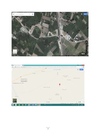
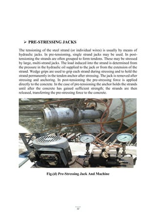
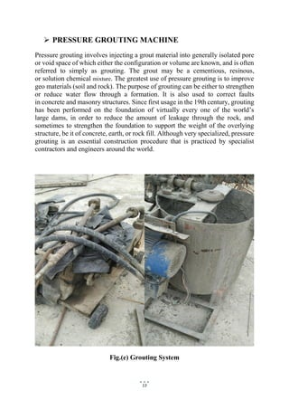
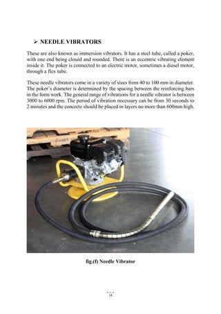


This document provides details about a summer training report completed by Ankit Gautam on an overhead bridge construction project by U.P. State Bridge Corporation Ltd. It includes information about the project location, duration, features of the project such as dimensions and materials used. It also describes the various machines and equipment used in construction including hydraulic cranes, concrete mixers, auto levels, and pre-stressing jacks. Finally, it discusses the key components of the bridge including reinforced earth walls, piers, bearings, and pre-stressing of concrete.


