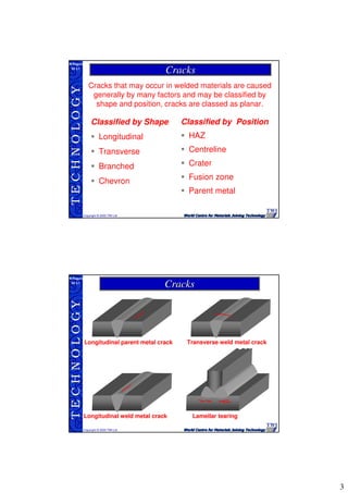
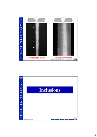
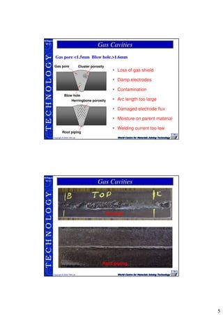
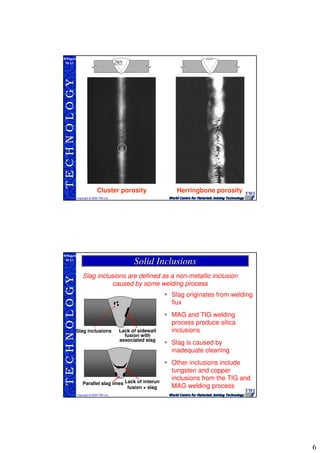
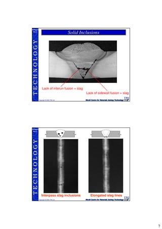
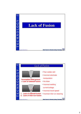
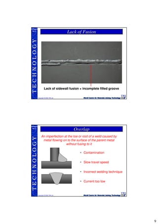
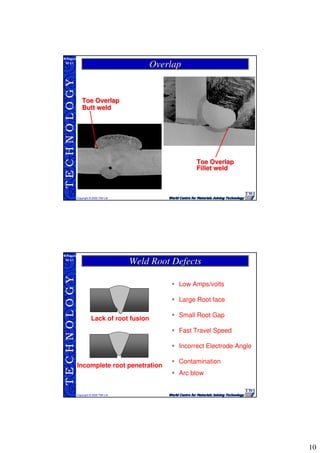
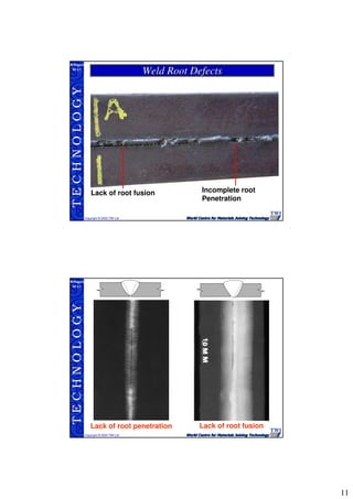
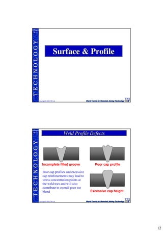
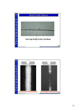
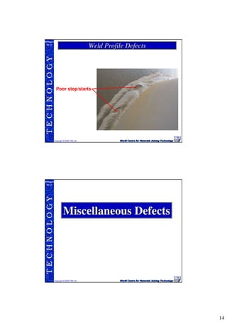
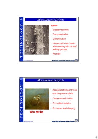
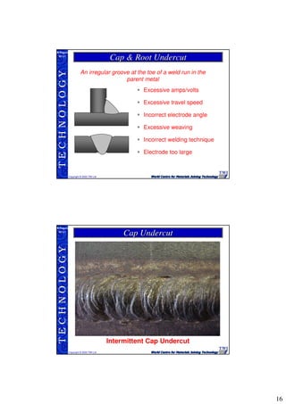
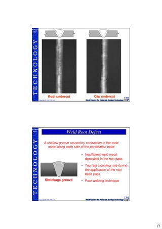
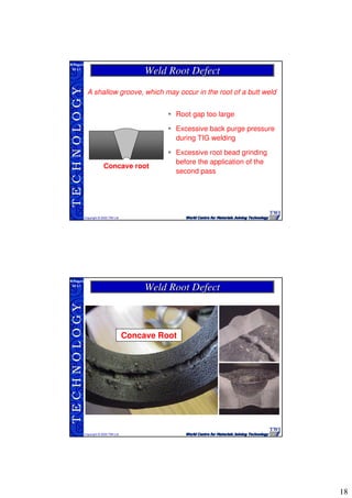
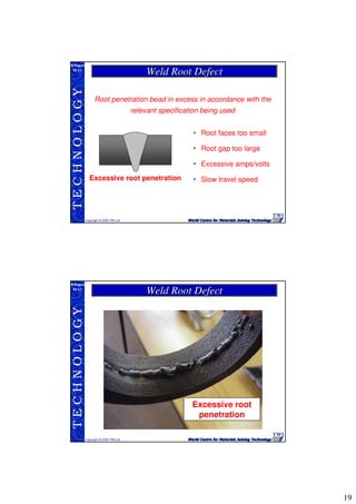
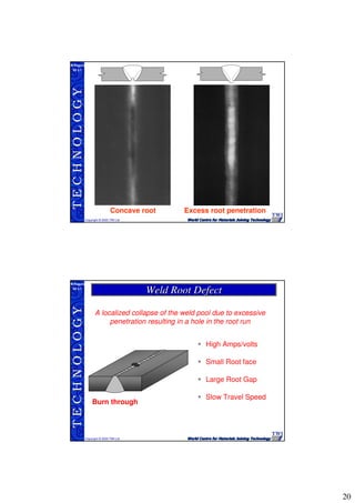
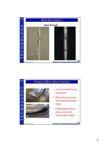
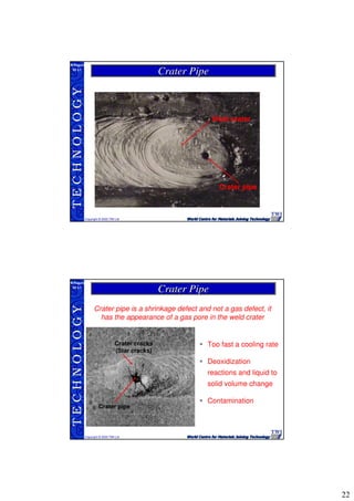
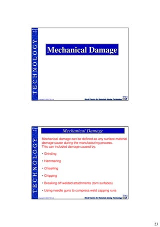
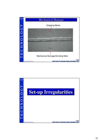
1
TECHNOLOGY
Copyright © 2005 TWI Ltd
WI 3.1
M.Rogers
Welding Imperfections
Course notes section reference 3
TECHNOLOGY
Copyright © 2005 TWI Ltd
WI 3.1
M.Rogers
Weld Defect ClassificationWeld Defect Classification
Defects can be grouped under three main
classifications
Planar Defects: linear from at least one dimension
• Cracks
• Lack of fusion
Linear Volumetric Defects: Linear in length with volume
• Slag lines
• lack of fusion with associated slag
• Piping.
Non-planar defects: rounded indications without significat length
• Slag inclusions
• Gas pores/blow holes.
• Other matallic and non-matallic inclusions
2
TECHNOLOGY
Copyright © 2005 TWI Ltd
WI 3.1
M.Rogers
Defects which may be detected by visual inspection
can be grouped under the following headings
Cracks
Solid inclusions
Surface and profiles
Misalignment (set-up
irregularities)
Gas pores and porosity
Lack of fusion
Mechanical damage
Parent material damage
Miscellaneous
Faults in Fusion WeldsFaults in Fusion Welds
TECHNOLOGY
Copyright © 2005 TWI Ltd
WI 3.1
M.Rogers
CracksCracks
3
TECHNOLOGY
Copyright © 2005 TWI Ltd
WI 3.1
M.Rogers
Classified by Shape
Longitudinal
Transverse
Branched
Chevron
Classified by Position
HAZ
Centreline
Crater
Fusion zone
Parent metal
Cracks that may occur in welded materials are caused
generally by many factors and may be classified by
shape and position, cracks are classed as planar.
CracksCracks
TECHNOLOGY
Copyright © 2005 TWI Ltd
WI 3.1
M.Rogers
Longitudinal parent metal crack
Longitudinal weld metal crack Lamellar tearing
Transverse weld metal crack
CracksCracks
4
TECHNOLOGY
Copyright © 2005 TWI Ltd
WI 3.1
M.Rogers
Transverse crack Longitudinal crack
TECHNOLOGY
Copyright © 2005 TWI Ltd
WI 3.1
M.Rogers
InclusionsInclusions
5
TECHNOLOGY
Copyright © 2005 TWI Ltd
WI 3.1
M.Rogers
Root piping
Cluster porosityGas pore
Blow hole
Herringbone porosity
Loss of gas shield
Damp electrodes
Contamination
Arc length too large
Damaged electrode flux
Moisture on parent material
Welding current too low
Gas pore <1.5mm Blow hole.>1.6mm
Gas CavitiesGas Cavities
TECHNOLOGY
Copyright © 2005 TWI Ltd
WI 3.1
M.Rogers
Root piping
Porosity
Gas CavitiesGas Cavities
6
TECHNOLOGY
Copyright © 2005 TWI Ltd
WI 3.1
M.Rogers
Cluster porosity Herringbone porosity
TECHNOLOGY
Copyright © 2005 TWI Ltd
WI 3.1
M.Rogers
Slag originates from welding
flux
MAG and TIG welding
process produce silica
inclusions
Slag is caused by
inadequate cleaning
Other inclusions include
tungsten and copper
inclusions from the TIG and
MAG welding process
Slag inclusions are defined as a non-metallic inclusion
caused by some welding process
Slag inclusions
Parallel slag lines Lack of interun
fusion + slag
Lack of sidewall
fusion with
associated slag
Solid InclusionsSolid Inclusions
7
TECHNOLOGY
Copyright © 2005 TWI Ltd
WI 3.1
M.Rogers
Solid InclusionsSolid Inclusions
Lack of interun fusion + slag
Lack of sidewall fusion + slag
TECHNOLOGY
Copyright © 2005 TWI Ltd
WI 3.1
M.Rogers
Elongated slag linesInterpass slag inclusions
8
TECHNOLOGY
Copyright © 2005 TWI Ltd
WI 3.1
M.Rogers
Lack of FusionLack of Fusion
TECHNOLOGY
Copyright © 2005 TWI Ltd
WI 3.1
M.Rogers
Incomplete filled groove
+ Lack of sidewall fusion
1
2
1. Lack of sidewall fusion
2. Lack of inter-run fusion
Poor welder skill
Incorrect electrode
manipulation
Arc blow
Incorrect welding
current/voltage
Incorrect travel speed
Incorrect inter-run cleaning
Lack of FusionLack of Fusion
9
TECHNOLOGY
Copyright © 2005 TWI Ltd
WI 3.1
M.Rogers
Lack of FusionLack of Fusion
Lack of sidewall fusion + incomplete filled groove
TECHNOLOGY
Copyright © 2005 TWI Ltd
WI 3.1
M.Rogers
An imperfection at the toe or root of a weld caused by
metal flowing on to the surface of the parent metal
without fusing to it
Contamination
Slow travel speed
Incorrect welding technique
Current too low
OverlapOverlap
10
TECHNOLOGY
Copyright © 2005 TWI Ltd
WI 3.1
M.Rogers
Toe OverlapToe Overlap
Fillet weldFillet weld
Toe OverlapToe Overlap
Butt weldButt weld
OverlapOverlap
TECHNOLOGY
Copyright © 2005 TWI Ltd
WI 3.1
M.Rogers
Lack of root fusion
Incomplete root penetration
Low Amps/volts
Large Root face
Small Root Gap
Fast Travel Speed
Incorrect Electrode Angle
Contamination
Arc blow
Weld Root DefectsWeld Root Defects
11
TECHNOLOGY
Copyright © 2005 TWI Ltd
WI 3.1
M.Rogers
Lack of root fusion Incomplete root
Penetration
Weld Root DefectsWeld Root Defects
TECHNOLOGY
Copyright © 2005 TWI Ltd
WI 3.1
M.Rogers
Lack of root penetration Lack of root fusion
12
TECHNOLOGY
Copyright © 2005 TWI Ltd
WI 3.1
M.Rogers
Surface & ProfileSurface & Profile
TECHNOLOGY
Copyright © 2005 TWI Ltd
WI 3.1
M.Rogers
Incomplete filled groove Poor cap profile
Excessive cap height
Poor cap profiles and excessive
cap reinforcements may lead to
stress concentration points at
the weld toes and will also
contribute to overall poor toe
blend
Weld Profile DefectsWeld Profile Defects
13
TECHNOLOGY
Copyright © 2005 TWI Ltd
WI 3.1
M.Rogers
Weld Profile DefectsWeld Profile Defects
Poor Cap Profile & Poor Toe Blend
TECHNOLOGY
Copyright © 2005 TWI Ltd
WI 3.1
M.Rogers
Incomplete filled grooveExcess cap reinforcement
14
TECHNOLOGY
Copyright © 2005 TWI Ltd
WI 3.1
M.Rogers
Poor stop/starts
Weld Profile DefectsWeld Profile Defects
TECHNOLOGY
Copyright © 2005 TWI Ltd
WI 3.1
M.Rogers
Miscellaneous DefectsMiscellaneous Defects
15
TECHNOLOGY
Copyright © 2005 TWI Ltd
WI 3.1
M.Rogers
Spatter
Excessive current
Damp electrodes
Contamination
Incorrect wire feed speed
when welding with the MAG
welding process
Arc blow
Miscellaneous DefectsMiscellaneous Defects
TECHNOLOGY
Copyright © 2005 TWI Ltd
WI 3.1
M.Rogers
Accidental striking of the arc
onto the parent material
Faulty electrode holder
Poor cable insulation
Poor return lead clamping
Arc strike
Miscellaneous DefectsMiscellaneous Defects
16
TECHNOLOGY
Copyright © 2005 TWI Ltd
WI 3.1
M.Rogers
An irregular groove at the toe of a weld run in the
parent metal
Excessive amps/volts
Excessive travel speed
Incorrect electrode angle
Excessive weaving
Incorrect welding technique
Electrode too large
Cap & Root UndercutCap & Root Undercut
TECHNOLOGY
Copyright © 2005 TWI Ltd
WI 3.1
M.Rogers
Intermittent Cap Undercut
Cap UndercutCap Undercut
17
TECHNOLOGY
Copyright © 2005 TWI Ltd
WI 3.1
M.Rogers
Cap undercutRoot undercut
TECHNOLOGY
Copyright © 2005 TWI Ltd
WI 3.1
M.Rogers
Shrinkage groove
Insufficient weld metal
deposited in the root pass
Too fast a cooling rate during
the application of the root
bead pass
Poor welding technique
A shallow groove caused by contraction in the weld
metal along each side of the penetration bead
Weld Root DefectWeld Root Defect
18
TECHNOLOGY
Copyright © 2005 TWI Ltd
WI 3.1
M.Rogers
Concave root
Root gap too large
Excessive back purge pressure
during TIG welding
Excessive root bead grinding
before the application of the
second pass
A shallow groove, which may occur in the root of a butt weld
Weld Root DefectWeld Root Defect
TECHNOLOGY
Copyright © 2005 TWI Ltd
WI 3.1
M.Rogers
Concave Root
Weld Root DefectWeld Root Defect
19
TECHNOLOGY
Copyright © 2005 TWI Ltd
WI 3.1
M.Rogers
Excessive root penetration
Root faces too small
Root gap too large
Excessive amps/volts
Slow travel speed
Root penetration bead in excess in accordance with the
relevant specification being used
Weld Root DefectWeld Root Defect
TECHNOLOGY
Copyright © 2005 TWI Ltd
WI 3.1
M.Rogers
Weld Root DefectWeld Root Defect
Excessive root
penetration
20
TECHNOLOGY
Copyright © 2005 TWI Ltd
WI 3.1
M.Rogers
Concave root Excess root penetration
TECHNOLOGY
Copyright © 2005 TWI Ltd
WI 3.1
M.Rogers
High Amps/volts
Small Root face
Large Root Gap
Slow Travel Speed
Burn through
A localized collapse of the weld pool due to excessive
penetration resulting in a hole in the root run
Weld Root DefectWeld Root Defect
21
TECHNOLOGY
Copyright © 2005 TWI Ltd
WI 3.1
M.Rogers
Weld Root DefectWeld Root Defect
Burn Through
TECHNOLOGY
Copyright © 2005 TWI Ltd
WI 3.1
M.Rogers
Loss or insufficient back
purging gas
Most commonly occurs
when welding stainless
steels
Purging gases include
argon, helium and
occasionally nitrogen
Oxidized Root (Root Coking)Oxidized Root (Root Coking)
22
TECHNOLOGY
Copyright © 2005 TWI Ltd
WI 3.1
M.Rogers
Crater pipe
Weld crater
Crater PipeCrater Pipe
TECHNOLOGY
Copyright © 2005 TWI Ltd
WI 3.1
M.Rogers
Crater pipe is a shrinkage defect and not a gas defect, it
has the appearance of a gas pore in the weld crater
Too fast a cooling rate
Deoxidization
reactions and liquid to
solid volume change
Contamination
Crater cracks
(Star cracks)
Crater pipe
Crater PipeCrater Pipe
23
TECHNOLOGY
Copyright © 2005 TWI Ltd
WI 3.1
M.Rogers
Mechanical DamageMechanical Damage
TECHNOLOGY
Copyright © 2005 TWI Ltd
WI 3.1
M.Rogers
Mechanical damage can be defined as any surface material
damage cause during the manufacturing process.
This can included damage caused by:
Grinding
Hammering
Chiselling
Chipping
Breaking off welded attachments (torn surfaces)
Using needle guns to compress weld capping runs
Mechanical DamageMechanical Damage
24
TECHNOLOGY
Copyright © 2005 TWI Ltd
WI 3.1
M.Rogers
Mechanical DamageMechanical Damage
Mechanical Damage/Grinding Mark
Chipping Marks
TECHNOLOGY
Copyright © 2005 TWI Ltd
WI 3.1
M.Rogers
SetSet--up Irregularitiesup Irregularities
25
TECHNOLOGY
Copyright © 2005 TWI Ltd
WI 3.1
M.Rogers
A variation of leg lengths on a fillet weld
Note: Unequal leg lengths on a fillet weld may be specified
as part of the design, in which case it will not be
considered as a defect.
Unequal Leg LengthsUnequal Leg Lengths
TECHNOLOGY
Copyright © 2005 TWI Ltd
WI 3.1
M.Rogers
Plate/pipe Linear Misalignment
(Hi-Lo)
Angular Misalignment
Linear misalignment is
measured from the lowest
plate to the highest point.
Angular misalignment is
measured in degrees
SetSet--up Irregularitiesup Irregularities
26
TECHNOLOGY
Copyright © 2005 TWI Ltd
WI 3.1
M.Rogers
Linear Misalignment
SetSet--up Irregularitiesup Irregularities
TECHNOLOGY
Copyright © 2005 TWI Ltd
WI 3.1
M.Rogers
Linear Misalignment
SetSet--up Irregularitiesup Irregularities

Welding defects

  • 1.
    1 TECHNOLOGY Copyright © 2005TWI Ltd WI 3.1 M.Rogers Welding Imperfections Course notes section reference 3 TECHNOLOGY Copyright © 2005 TWI Ltd WI 3.1 M.Rogers Weld Defect ClassificationWeld Defect Classification Defects can be grouped under three main classifications Planar Defects: linear from at least one dimension • Cracks • Lack of fusion Linear Volumetric Defects: Linear in length with volume • Slag lines • lack of fusion with associated slag • Piping. Non-planar defects: rounded indications without significat length • Slag inclusions • Gas pores/blow holes. • Other matallic and non-matallic inclusions
  • 2.
    2 TECHNOLOGY Copyright © 2005TWI Ltd WI 3.1 M.Rogers Defects which may be detected by visual inspection can be grouped under the following headings Cracks Solid inclusions Surface and profiles Misalignment (set-up irregularities) Gas pores and porosity Lack of fusion Mechanical damage Parent material damage Miscellaneous Faults in Fusion WeldsFaults in Fusion Welds TECHNOLOGY Copyright © 2005 TWI Ltd WI 3.1 M.Rogers CracksCracks
  • 3.
    3 TECHNOLOGY Copyright © 2005TWI Ltd WI 3.1 M.Rogers Classified by Shape Longitudinal Transverse Branched Chevron Classified by Position HAZ Centreline Crater Fusion zone Parent metal Cracks that may occur in welded materials are caused generally by many factors and may be classified by shape and position, cracks are classed as planar. CracksCracks TECHNOLOGY Copyright © 2005 TWI Ltd WI 3.1 M.Rogers Longitudinal parent metal crack Longitudinal weld metal crack Lamellar tearing Transverse weld metal crack CracksCracks
  • 4.
    4 TECHNOLOGY Copyright © 2005TWI Ltd WI 3.1 M.Rogers Transverse crack Longitudinal crack TECHNOLOGY Copyright © 2005 TWI Ltd WI 3.1 M.Rogers InclusionsInclusions
  • 5.
    5 TECHNOLOGY Copyright © 2005TWI Ltd WI 3.1 M.Rogers Root piping Cluster porosityGas pore Blow hole Herringbone porosity Loss of gas shield Damp electrodes Contamination Arc length too large Damaged electrode flux Moisture on parent material Welding current too low Gas pore <1.5mm Blow hole.>1.6mm Gas CavitiesGas Cavities TECHNOLOGY Copyright © 2005 TWI Ltd WI 3.1 M.Rogers Root piping Porosity Gas CavitiesGas Cavities
  • 6.
    6 TECHNOLOGY Copyright © 2005TWI Ltd WI 3.1 M.Rogers Cluster porosity Herringbone porosity TECHNOLOGY Copyright © 2005 TWI Ltd WI 3.1 M.Rogers Slag originates from welding flux MAG and TIG welding process produce silica inclusions Slag is caused by inadequate cleaning Other inclusions include tungsten and copper inclusions from the TIG and MAG welding process Slag inclusions are defined as a non-metallic inclusion caused by some welding process Slag inclusions Parallel slag lines Lack of interun fusion + slag Lack of sidewall fusion with associated slag Solid InclusionsSolid Inclusions
  • 7.
    7 TECHNOLOGY Copyright © 2005TWI Ltd WI 3.1 M.Rogers Solid InclusionsSolid Inclusions Lack of interun fusion + slag Lack of sidewall fusion + slag TECHNOLOGY Copyright © 2005 TWI Ltd WI 3.1 M.Rogers Elongated slag linesInterpass slag inclusions
  • 8.
    8 TECHNOLOGY Copyright © 2005TWI Ltd WI 3.1 M.Rogers Lack of FusionLack of Fusion TECHNOLOGY Copyright © 2005 TWI Ltd WI 3.1 M.Rogers Incomplete filled groove + Lack of sidewall fusion 1 2 1. Lack of sidewall fusion 2. Lack of inter-run fusion Poor welder skill Incorrect electrode manipulation Arc blow Incorrect welding current/voltage Incorrect travel speed Incorrect inter-run cleaning Lack of FusionLack of Fusion
  • 9.
    9 TECHNOLOGY Copyright © 2005TWI Ltd WI 3.1 M.Rogers Lack of FusionLack of Fusion Lack of sidewall fusion + incomplete filled groove TECHNOLOGY Copyright © 2005 TWI Ltd WI 3.1 M.Rogers An imperfection at the toe or root of a weld caused by metal flowing on to the surface of the parent metal without fusing to it Contamination Slow travel speed Incorrect welding technique Current too low OverlapOverlap
  • 10.
    10 TECHNOLOGY Copyright © 2005TWI Ltd WI 3.1 M.Rogers Toe OverlapToe Overlap Fillet weldFillet weld Toe OverlapToe Overlap Butt weldButt weld OverlapOverlap TECHNOLOGY Copyright © 2005 TWI Ltd WI 3.1 M.Rogers Lack of root fusion Incomplete root penetration Low Amps/volts Large Root face Small Root Gap Fast Travel Speed Incorrect Electrode Angle Contamination Arc blow Weld Root DefectsWeld Root Defects
  • 11.
    11 TECHNOLOGY Copyright © 2005TWI Ltd WI 3.1 M.Rogers Lack of root fusion Incomplete root Penetration Weld Root DefectsWeld Root Defects TECHNOLOGY Copyright © 2005 TWI Ltd WI 3.1 M.Rogers Lack of root penetration Lack of root fusion
  • 12.
    12 TECHNOLOGY Copyright © 2005TWI Ltd WI 3.1 M.Rogers Surface & ProfileSurface & Profile TECHNOLOGY Copyright © 2005 TWI Ltd WI 3.1 M.Rogers Incomplete filled groove Poor cap profile Excessive cap height Poor cap profiles and excessive cap reinforcements may lead to stress concentration points at the weld toes and will also contribute to overall poor toe blend Weld Profile DefectsWeld Profile Defects
  • 13.
    13 TECHNOLOGY Copyright © 2005TWI Ltd WI 3.1 M.Rogers Weld Profile DefectsWeld Profile Defects Poor Cap Profile & Poor Toe Blend TECHNOLOGY Copyright © 2005 TWI Ltd WI 3.1 M.Rogers Incomplete filled grooveExcess cap reinforcement
  • 14.
    14 TECHNOLOGY Copyright © 2005TWI Ltd WI 3.1 M.Rogers Poor stop/starts Weld Profile DefectsWeld Profile Defects TECHNOLOGY Copyright © 2005 TWI Ltd WI 3.1 M.Rogers Miscellaneous DefectsMiscellaneous Defects
  • 15.
    15 TECHNOLOGY Copyright © 2005TWI Ltd WI 3.1 M.Rogers Spatter Excessive current Damp electrodes Contamination Incorrect wire feed speed when welding with the MAG welding process Arc blow Miscellaneous DefectsMiscellaneous Defects TECHNOLOGY Copyright © 2005 TWI Ltd WI 3.1 M.Rogers Accidental striking of the arc onto the parent material Faulty electrode holder Poor cable insulation Poor return lead clamping Arc strike Miscellaneous DefectsMiscellaneous Defects
  • 16.
    16 TECHNOLOGY Copyright © 2005TWI Ltd WI 3.1 M.Rogers An irregular groove at the toe of a weld run in the parent metal Excessive amps/volts Excessive travel speed Incorrect electrode angle Excessive weaving Incorrect welding technique Electrode too large Cap & Root UndercutCap & Root Undercut TECHNOLOGY Copyright © 2005 TWI Ltd WI 3.1 M.Rogers Intermittent Cap Undercut Cap UndercutCap Undercut
  • 17.
    17 TECHNOLOGY Copyright © 2005TWI Ltd WI 3.1 M.Rogers Cap undercutRoot undercut TECHNOLOGY Copyright © 2005 TWI Ltd WI 3.1 M.Rogers Shrinkage groove Insufficient weld metal deposited in the root pass Too fast a cooling rate during the application of the root bead pass Poor welding technique A shallow groove caused by contraction in the weld metal along each side of the penetration bead Weld Root DefectWeld Root Defect
  • 18.
    18 TECHNOLOGY Copyright © 2005TWI Ltd WI 3.1 M.Rogers Concave root Root gap too large Excessive back purge pressure during TIG welding Excessive root bead grinding before the application of the second pass A shallow groove, which may occur in the root of a butt weld Weld Root DefectWeld Root Defect TECHNOLOGY Copyright © 2005 TWI Ltd WI 3.1 M.Rogers Concave Root Weld Root DefectWeld Root Defect
  • 19.
    19 TECHNOLOGY Copyright © 2005TWI Ltd WI 3.1 M.Rogers Excessive root penetration Root faces too small Root gap too large Excessive amps/volts Slow travel speed Root penetration bead in excess in accordance with the relevant specification being used Weld Root DefectWeld Root Defect TECHNOLOGY Copyright © 2005 TWI Ltd WI 3.1 M.Rogers Weld Root DefectWeld Root Defect Excessive root penetration
  • 20.
    20 TECHNOLOGY Copyright © 2005TWI Ltd WI 3.1 M.Rogers Concave root Excess root penetration TECHNOLOGY Copyright © 2005 TWI Ltd WI 3.1 M.Rogers High Amps/volts Small Root face Large Root Gap Slow Travel Speed Burn through A localized collapse of the weld pool due to excessive penetration resulting in a hole in the root run Weld Root DefectWeld Root Defect
  • 21.
    21 TECHNOLOGY Copyright © 2005TWI Ltd WI 3.1 M.Rogers Weld Root DefectWeld Root Defect Burn Through TECHNOLOGY Copyright © 2005 TWI Ltd WI 3.1 M.Rogers Loss or insufficient back purging gas Most commonly occurs when welding stainless steels Purging gases include argon, helium and occasionally nitrogen Oxidized Root (Root Coking)Oxidized Root (Root Coking)
  • 22.
    22 TECHNOLOGY Copyright © 2005TWI Ltd WI 3.1 M.Rogers Crater pipe Weld crater Crater PipeCrater Pipe TECHNOLOGY Copyright © 2005 TWI Ltd WI 3.1 M.Rogers Crater pipe is a shrinkage defect and not a gas defect, it has the appearance of a gas pore in the weld crater Too fast a cooling rate Deoxidization reactions and liquid to solid volume change Contamination Crater cracks (Star cracks) Crater pipe Crater PipeCrater Pipe
  • 23.
    23 TECHNOLOGY Copyright © 2005TWI Ltd WI 3.1 M.Rogers Mechanical DamageMechanical Damage TECHNOLOGY Copyright © 2005 TWI Ltd WI 3.1 M.Rogers Mechanical damage can be defined as any surface material damage cause during the manufacturing process. This can included damage caused by: Grinding Hammering Chiselling Chipping Breaking off welded attachments (torn surfaces) Using needle guns to compress weld capping runs Mechanical DamageMechanical Damage
  • 24.
    24 TECHNOLOGY Copyright © 2005TWI Ltd WI 3.1 M.Rogers Mechanical DamageMechanical Damage Mechanical Damage/Grinding Mark Chipping Marks TECHNOLOGY Copyright © 2005 TWI Ltd WI 3.1 M.Rogers SetSet--up Irregularitiesup Irregularities
  • 25.
    25 TECHNOLOGY Copyright © 2005TWI Ltd WI 3.1 M.Rogers A variation of leg lengths on a fillet weld Note: Unequal leg lengths on a fillet weld may be specified as part of the design, in which case it will not be considered as a defect. Unequal Leg LengthsUnequal Leg Lengths TECHNOLOGY Copyright © 2005 TWI Ltd WI 3.1 M.Rogers Plate/pipe Linear Misalignment (Hi-Lo) Angular Misalignment Linear misalignment is measured from the lowest plate to the highest point. Angular misalignment is measured in degrees SetSet--up Irregularitiesup Irregularities
  • 26.
    26 TECHNOLOGY Copyright © 2005TWI Ltd WI 3.1 M.Rogers Linear Misalignment SetSet--up Irregularitiesup Irregularities TECHNOLOGY Copyright © 2005 TWI Ltd WI 3.1 M.Rogers Linear Misalignment SetSet--up Irregularitiesup Irregularities