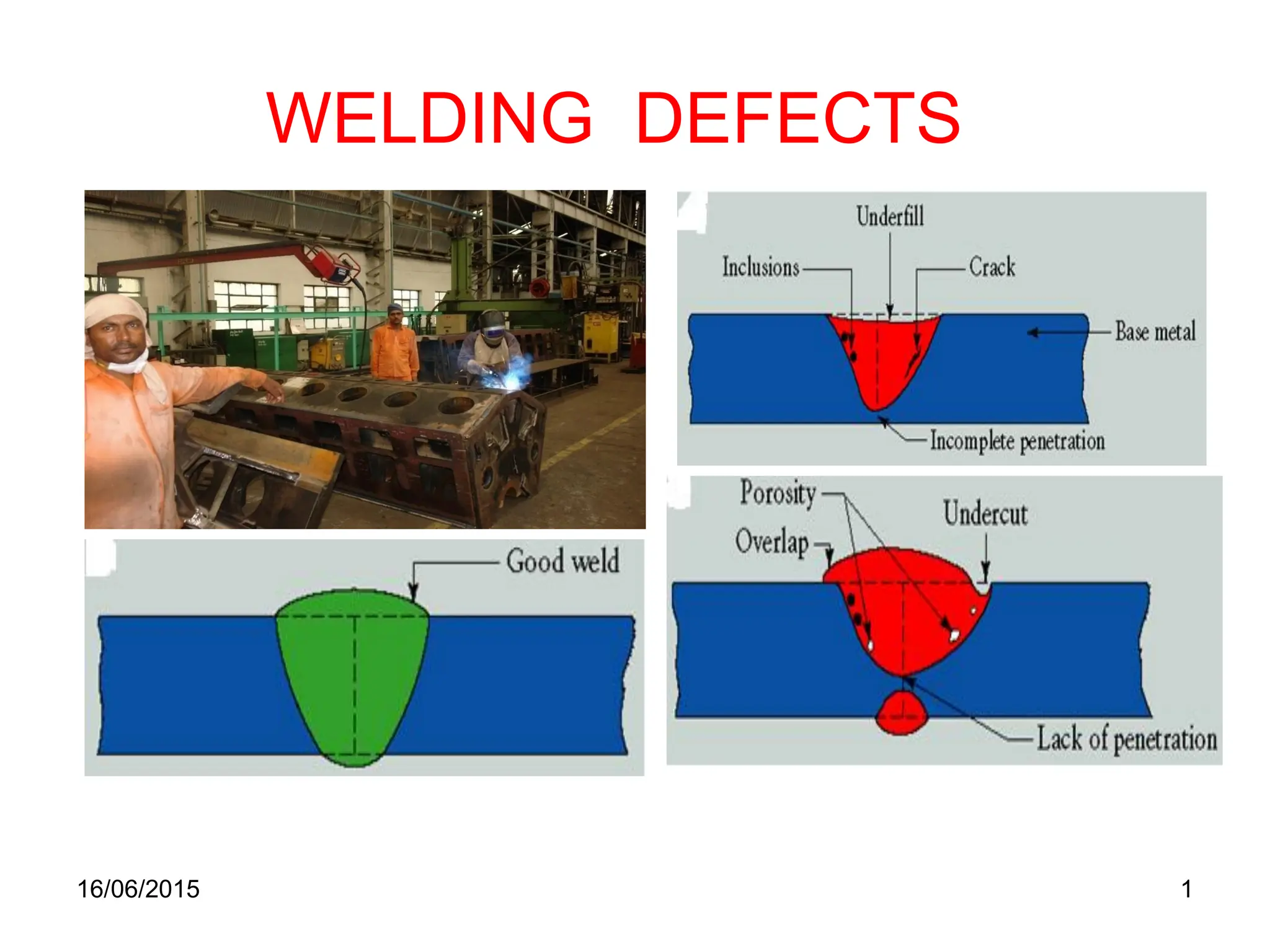
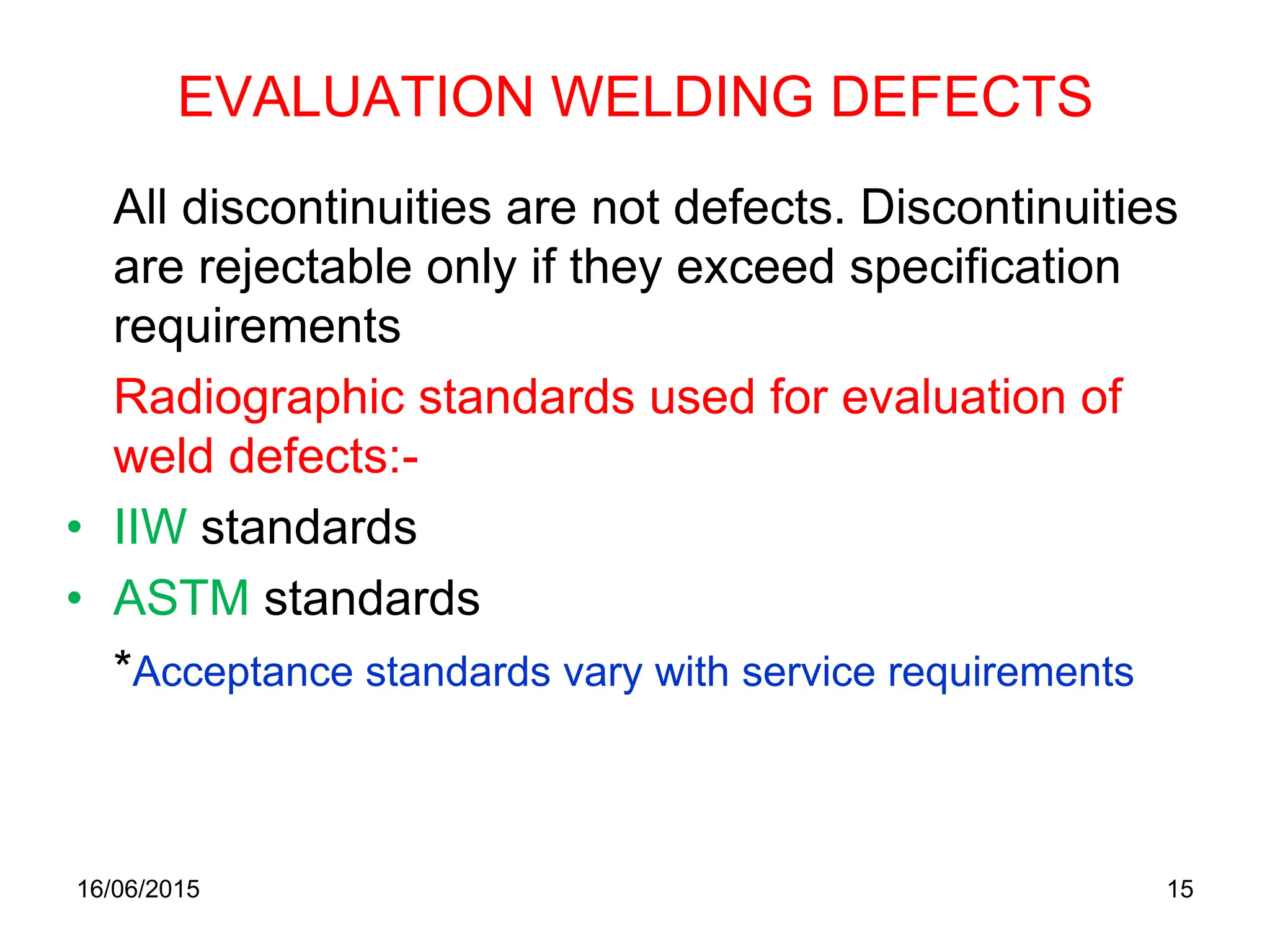
The document details welding defects, their definitions, causes, and remedies, emphasizing the importance of defect-free weld joints for structural integrity. It classifies defects into categories such as cracks, cavities, and inclusions, explaining their origins and prevention methods. Additionally, it discusses standard evaluation criteria for weld quality based on international standards and outlines corrective actions for when defects are identified.
![16/06/2015 4
DEFINITION OF WELDING
Definition:
“Process of joining two similar or dissimilar metals by
heat or by pressure or by both using a filler metal to
achieve a defect less joint having the physical
properties similar to that of parent metal”.
Dissimilar metal means:-
• Those that are chemically different (steel,Cu, Al, etc).
• Those that are metallurgically different (MS, SS, etc).
*Dissimilar metal imparts galvanic cell corrosion
Commonly welded base metals:-
– Ferrous-[WI, CI, C-steel (low, med, high), alloy
steel, SS]
– Non-ferrous-(Al, Cu ,Mg, Ni, Zn & their alloys)](https://image.slidesharecdn.com/1434529014349-weldingdefects-240527170632-2659b832/75/TYPES-OF-WELDING-DEFECTS-AND-HOW-TO-PREVENT-4-2048.jpg)

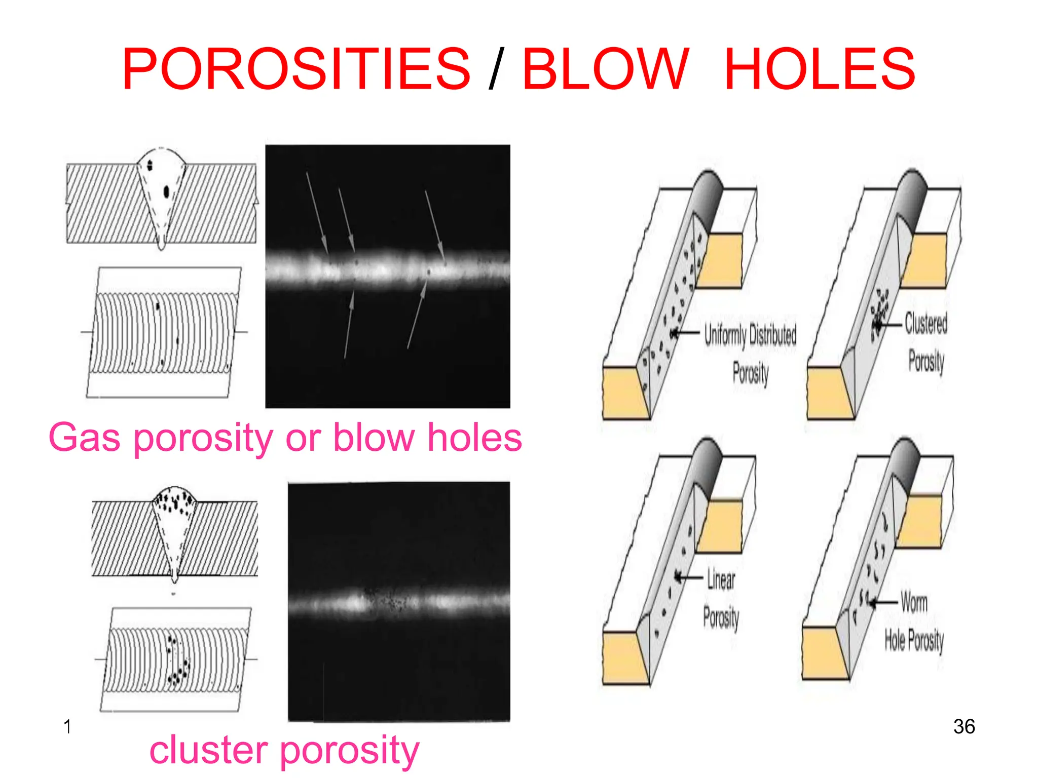
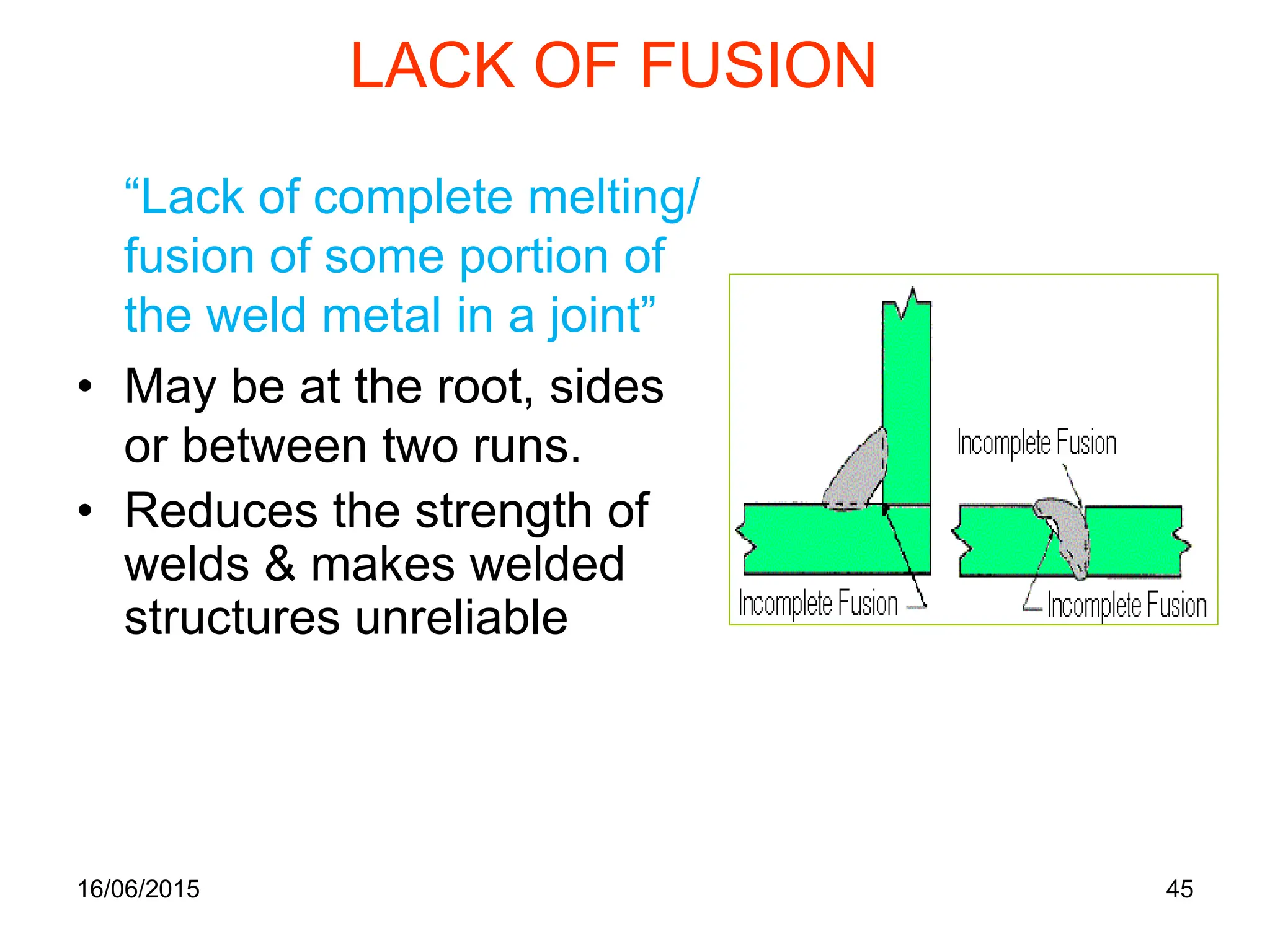
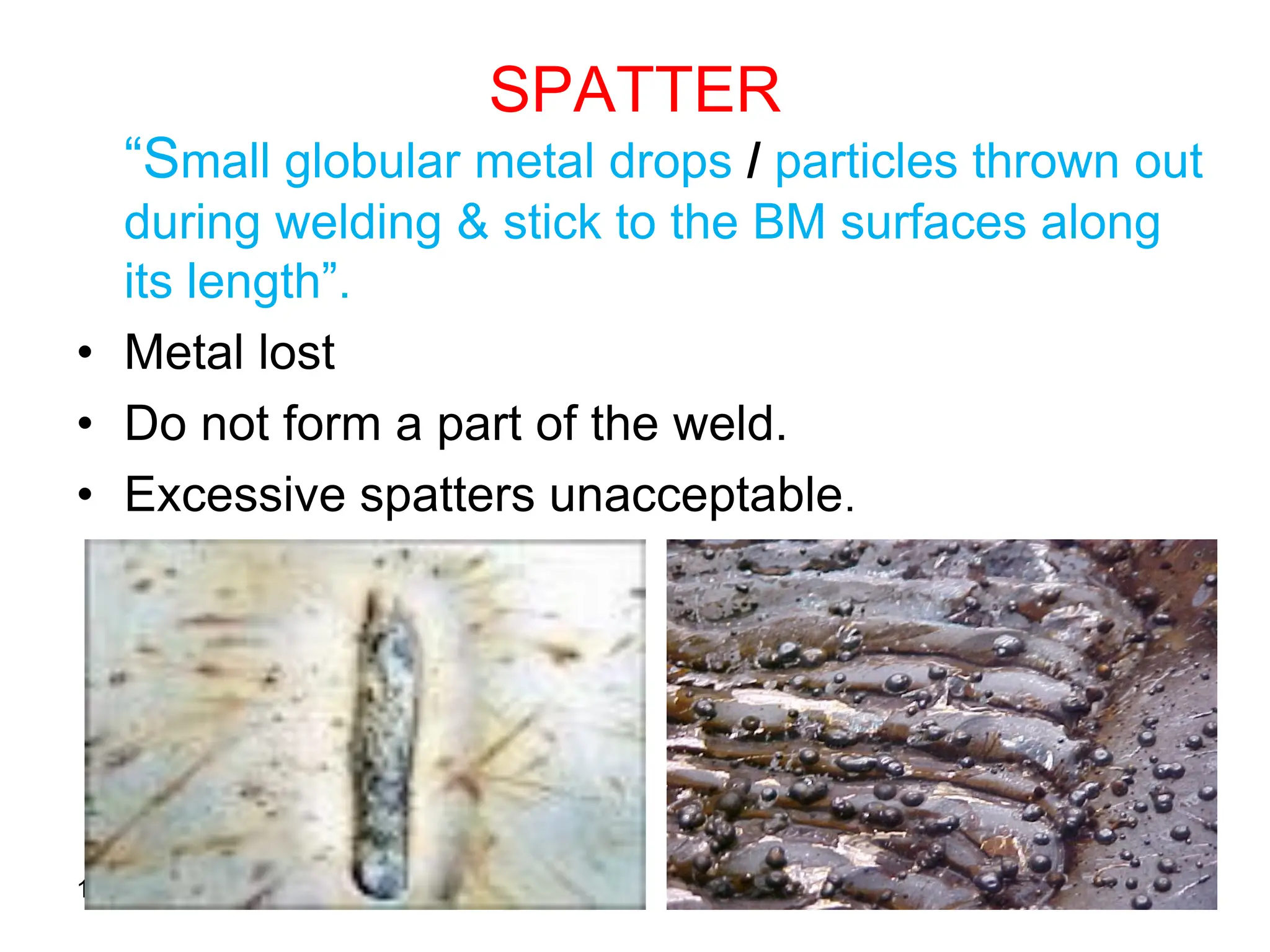
![POROSITIES/BLOW HOLES
“Porosity is a group of small voids, where
as blow holes are comparatively bigger
hole or cavity caused by entrapment of
gases [gases:H2,CO,CO2,N2 &O2 from
coating ingredients in the electrode or
moisture, oil, grease, rust, etc on BM]
within the solidified weld”.
• Porosity can occur on or just below the
surface of a weld.
• Porosity in the weld and HAZ may lead to
cracking.
16/06/2015 35](https://image.slidesharecdn.com/1434529014349-weldingdefects-240527170632-2659b832/75/TYPES-OF-WELDING-DEFECTS-AND-HOW-TO-PREVENT-35-2048.jpg)
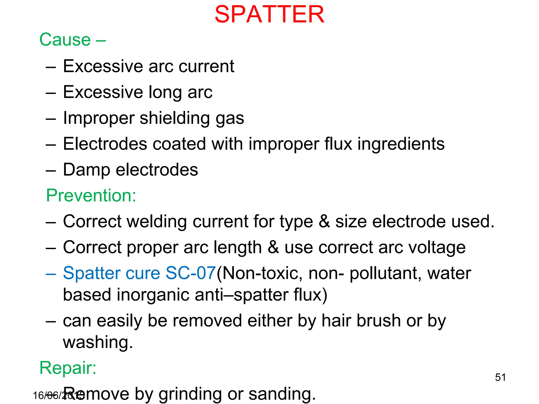
![BLOW HOLES / POROSITIES
Cause:
• Work piece or electrode
contains/contaminated
with:-
– High sulphur & carbon
– Excessive moisture, rust or
scale, oil, grease, etc
• Atmospheric gases [N2,
excessive O2 (Al-
welding)]
• Anodising coating on Al
(contains moisture)
• Long arc
• Fast solidification rate
Prevention:
• Preheat
• Maintain proper arc
length
• Use low hydrogen
electrode
• Use recommended
procedure for baking &
storing electrodes
• Clean joint surfaces &
adjacent surfaces
16/06/2015 37](https://image.slidesharecdn.com/1434529014349-weldingdefects-240527170632-2659b832/75/TYPES-OF-WELDING-DEFECTS-AND-HOW-TO-PREVENT-37-2048.jpg)


![Rtfi weld defects[1]](https://cdn.slidesharecdn.com/ss_thumbnails/rtfiwelddefects1-190507184037-thumbnail.jpg?width=640&height=640&fit=bounds)


